RFM9X.IoTCore Uputronics Raspberry PI LoRa(TM) Expansion Board

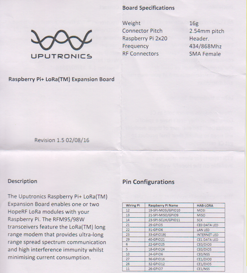
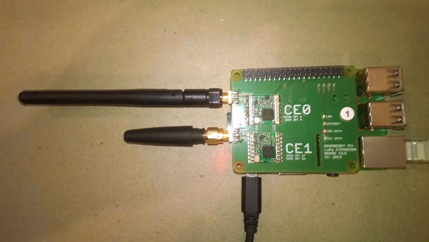
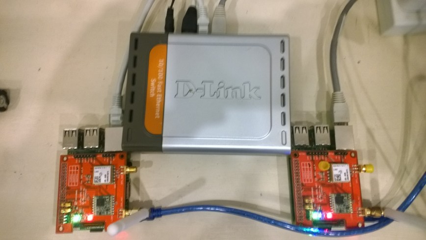
The Raspberry Pi+ LoRa(TM) Expansion Board has two RF modules. In my setup CE0 was 915MHz and CE1 was 433MHz so I modified the demo application so I could run both ports independently or simultaneously.

#if UPUTRONICS_RPIPLUS_CS0 && !UPUTRONICS_RPIPLUS_CS1
private const byte InterruptLine = 25;
private Rfm9XDevice rfm9XDevice = new Rfm9XDevice(ChipSelectPin.CS0, InterruptLine);
#endif
#if !UPUTRONICS_RPIPLUS_CS0 && UPUTRONICS_RPIPLUS_CS1
private const byte InterruptLine = 16;
private Rfm9XDevice rfm9XDevice = new Rfm9XDevice(ChipSelectPin.CS1, InterruptLine);
#endif
#if UPUTRONICS_RPIPLUS_CS0 && UPUTRONICS_RPIPLUS_CS1 // 433MHz and 915MHz in my setup
private const byte InterruptLineCS0 = 25;
private Rfm9XDevice rfm9XDeviceCS0 = new Rfm9XDevice(ChipSelectPin.CS0, InterruptLineCS0);
private const byte InterruptLineCS1 = 16;
private Rfm9XDevice rfm9XDeviceCS1 = new Rfm9XDevice(ChipSelectPin.CS1, InterruptLineCS1);
#endif

The in the run method

#if UPUTRONICS_RPIPLUS_CS0 && UPUTRONICS_RPIPLUS_CS1
public void Run(IBackgroundTaskInstance taskInstance)
{
rfm9XDeviceCS0.Initialise(915000000.0, paBoost: true, rxPayloadCrcOn: true);
rfm9XDeviceCS1.Initialise(433000000.0, paBoost: true, rxPayloadCrcOn: true);
#if DEBUG
rfm9XDeviceCS0.RegisterDump();
rfm9XDeviceCS1.RegisterDump();
#endif

rfm9XDeviceCS0.OnReceive += Rfm9XDevice_OnReceive;
rfm9XDeviceCS1.OnReceive += Rfm9XDevice_OnReceive;
#if ADDRESSED_MESSAGES_PAYLOAD
rfm9XDeviceCS0.Receive(UTF8Encoding.UTF8.GetBytes(Environment.MachineName));
rfm9XDeviceCS1.Receive(UTF8Encoding.UTF8.GetBytes(Environment.MachineName));
#else
rfm9XDeviceCS0.Receive();
rfm9XDeviceCS1.Receive();
#endif
rfm9XDeviceCS0.OnTransmit += Rfm9XDevice_OnTransmit;
rfm9XDeviceCS1.OnTransmit += Rfm9XDevice_OnTransmit;

Task.Delay(10000).Wait();

while (true)
{
string messageText = string.Format("Hello from {0} ! {1}", Environment.MachineName, MessageCount);
MessageCount -= 1;

byte[] messageBytes = UTF8Encoding.UTF8.GetBytes(messageText);
Debug.WriteLine("{0:HH:mm:ss}-TX {1} byte message {2}", DateTime.Now, messageBytes.Length, messageText);
#if ADDRESSED_MESSAGES_PAYLOAD
this.rfm9XDeviceCS0.Send(UTF8Encoding.UTF8.GetBytes("Netduino"), messageBytes);
this.rfm9XDeviceCS1.Send(UTF8Encoding.UTF8.GetBytes("Arduino1"), messageBytes);
#else
this.rfm9XDeviceCS0.Send(messageBytes);
this.rfm9XDeviceCS1.Send(messageBytes);
#endif
Task.Delay(10000).Wait();
}
}

#else

public void Run(IBackgroundTaskInstance taskInstance)
{
rfm9XDevice.Initialise(433000000, paBoost: true, rxPayloadCrcOn : true);
rfm9XDevice.Initialise(915000000, paBoost: true, rxPayloadCrcOn : true);
#if DEBUG
rfm9XDevice.RegisterDump();
#endif

rfm9XDevice.OnReceive += Rfm9XDevice_OnReceive;
#if ADDRESSED_MESSAGES_PAYLOAD
rfm9XDevice.Receive(UTF8Encoding.UTF8.GetBytes(Environment.MachineName));
#else
rfm9XDevice.Receive();
#endif
rfm9XDevice.OnTransmit += Rfm9XDevice_OnTransmit;

Task.Delay(10000).Wait();

while (true)
{
string messageText = string.Format("Hello from {0} ! {1}", Environment.MachineName, MessageCount);
MessageCount -= 1;

byte[] messageBytes = UTF8Encoding.UTF8.GetBytes(messageText);
Debug.WriteLine("{0:HH:mm:ss}-TX {1} byte message {2}", DateTime.Now, messageBytes.Length, messageText);
#if ADDRESSED_MESSAGES_PAYLOAD
this.rfm9XDevice.Send(UTF8Encoding.UTF8.GetBytes("AddressHere"), messageBytes);
#else
this.rfm9XDevice.Send(messageBytes);
#endif
Task.Delay(10000).Wait();
}
}
#endif

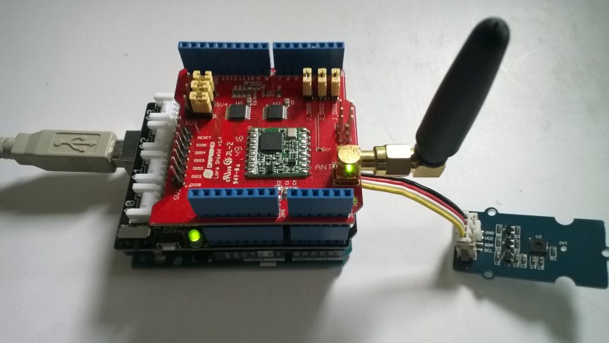
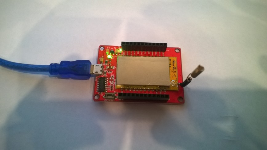
In the debugger output I could see addressed messages being sent to and arriving from a 433MHz Arduino device and a 915MHz Netduino device.

The thread 0x5f8 has exited with code 0 (0x0).
22:06:44-RX From Netduino PacketSnr 9.5 Packet RSSI -49dBm RSSI -110dBm = 20 byte message "Hello NetMF LoRa! 82"
22:06:47-RX From Arduino1 PacketSnr 9.8 Packet RSSI -56dBm RSSI -101dBm = 11 byte message "t 20.2,h 90"
22:06:48-TX 25 byte message Hello from LoRaIoT1 ! 163
22:06:49-TX Done
22:06:49-TX Done
The thread 0xe9c has exited with code 0 (0x0).
22:06:54-RX From Netduino PacketSnr 9.8 Packet RSSI -46dBm RSSI -111dBm = 20 byte message "Hello NetMF LoRa! 83"
22:06:57-RX From Arduino1 PacketSnr 9.8 Packet RSSI -61dBm RSSI -93dBm = 11 byte message "t 20.3,h 90"
22:06:58-TX 25 byte message Hello from LoRaIoT1 ! 162
22:06:59-TX Done
22:06:59-TX Done
The thread 0xf88 has exited with code 0 (0x0).
22:07:04-RX From Netduino PacketSnr 9.5 Packet RSSI -48dBm RSSI -110dBm = 20 byte message "Hello NetMF LoRa! 84"
22:07:07-RX From Arduino1 PacketSnr 9.8 Packet RSSI -61dBm RSSI -93dBm = 11 byte message "t 20.2,h 90"
22:07:09-TX 25 byte message Hello from LoRaIoT1 ! 161
22:07:09-TX Done
22:07:09-TX Done

This particular configuration has not been extensively tested yet and should be treated as early Beta (11 Sept 2018)


Uputronics Raspberry Pi+ LoRa(TM) Expansion Board

The second package to arrive was a Raspberry Pi+ LoRa(TM) Expansion Board populated with HopeRF 434MHz & 915MHz modules. It was in a small cardboard box with bolts+spacers and had a small set of printed instructions.

The shield has four user controlable Light Emitting Diodes(LED) connected to General Purpose Input Output(GPIO) pins which will be useful  for providing feedback when trying to debug faults etc..

uputronicsPiPlusHelp

Some of the pin numbers are also printed on the shield silk screen.UputronicsRPIPlusShield
This time the first step was to check the pin assignments of the 4 LEDs

//---------------------------------------------------------------------------------
// Copyright (c) September 2018, devMobile Software
//
// Licensed under the Apache License, Version 2.0 (the "License");
// you may not use this file except in compliance with the License.
// You may obtain a copy of the License at
//
//     http://www.apache.org/licenses/LICENSE-2.0
//
// Unless required by applicable law or agreed to in writing, software
// distributed under the License is distributed on an "AS IS" BASIS,
// WITHOUT WARRANTIES OR CONDITIONS OF ANY KIND, either express or implied.
// See the License for the specific language governing permissions and
// limitations under the License.
//
//---------------------------------------------------------------------------------
namespace devMobile.IoT.Rfm9x.UputronicsRPIPlusLed
{
using System;
using System.Threading;
using Windows.ApplicationModel.Background;
using Windows.Devices.Gpio;

public sealed class StartupTask : IBackgroundTask
{
public void Run(IBackgroundTaskInstance taskInstance)
{
GpioController gpioController = GpioController.GetDefault();

GpioPin ce01LedPin = gpioController.OpenPin(5);
ce01LedPin.SetDriveMode(GpioPinDriveMode.Output);
ce01LedPin.Write(GpioPinValue.Low);

GpioPin ceo2LedPin = gpioController.OpenPin(21);
ceo2LedPin.SetDriveMode(GpioPinDriveMode.Output);
ceo2LedPin.Write(GpioPinValue.High);

GpioPin lanLedPin = gpioController.OpenPin(6);
lanLedPin.SetDriveMode(GpioPinDriveMode.Output);
lanLedPin.Write(GpioPinValue.Low);

GpioPin internetLedPin = gpioController.OpenPin(13);
internetLedPin.SetDriveMode(GpioPinDriveMode.Output);
internetLedPin.Write(GpioPinValue.High);

while (true)
{
if (ce01LedPin.Read() == GpioPinValue.High)
{
ce01LedPin.Write(GpioPinValue.Low);
}
else
{
ce01LedPin.Write(GpioPinValue.High);
}

if (ceo2LedPin.Read() == GpioPinValue.High)
{
ceo2LedPin.Write(GpioPinValue.Low);
}
else
{
ceo2LedPin.Write(GpioPinValue.High);
}

if (lanLedPin.Read() == GpioPinValue.High)
{
lanLedPin.Write(GpioPinValue.Low);
}
else
{
lanLedPin.Write(GpioPinValue.High);
}

if (internetLedPin.Read() == GpioPinValue.High)
{
internetLedPin.Write(GpioPinValue.Low);
}
else
{
internetLedPin.Write(GpioPinValue.High);
}

Thread.Sleep(500);
}
}
}
}

I think there is a small issue with the internet LED it should be GPIO13 (which matches the pin number)

The next step was to get the Serial Peripheral Interface (SPI) interface for both modules working.

//---------------------------------------------------------------------------------
// Copyright (c) September 2018, devMobile Software
//
// Licensed under the Apache License, Version 2.0 (the "License");
// you may not use this file except in compliance with the License.
// You may obtain a copy of the License at
//
//     http://www.apache.org/licenses/LICENSE-2.0
//
// Unless required by applicable law or agreed to in writing, software
// distributed under the License is distributed on an "AS IS" BASIS,
// WITHOUT WARRANTIES OR CONDITIONS OF ANY KIND, either express or implied.
// See the License for the specific language governing permissions and
// limitations under the License.
//
//---------------------------------------------------------------------------------
namespace devMobile.IoT.Rfm9x.UputronicsRPIPlusSPI
{
using System;
using System.Diagnostics;
using System.Threading;
using Windows.ApplicationModel.Background;
using Windows.Devices.Spi;

public sealed class StartupTask : IBackgroundTask
{
public void Run(IBackgroundTaskInstance taskInstance)
{
#if CS0
const int chipSelectPinNumber = 0;
#endif
#if CS1
const int chipSelectPinNumber = 1;
#endif
SpiController spiController = SpiController.GetDefaultAsync().AsTask().GetAwaiter().GetResult();
var settings = new SpiConnectionSettings(chipSelectPinNumber)
{
ClockFrequency = 500000,
Mode = SpiMode.Mode0,   // From SemTech docs pg 80 CPOL=0, CPHA=0
};
SpiDevice Device = spiController.GetDevice(settings);

while (true)
{
byte[] writeBuffer = new byte[] { 0x42 }; // RegVersion
byte[] readBuffer = new byte[1];

// Read the RegVersion silicon ID to check SPI works
Device.TransferSequential(writeBuffer, readBuffer);

#if CS0
Debug.WriteLine("CS0 Register RegVer 0x{0:x2} - Value 0X{1:x2} - Bits {2}", writeBuffer[0], readBuffer[0], Convert.ToString(readBuffer[0], 2).PadLeft(8, '0'));
#endif
#if CS1
Debug.WriteLine("CS1 Register RegVer 0x{0:x2} - Value 0X{1:x2} - Bits {2}", writeBuffer[0], readBuffer[0], Convert.ToString(readBuffer[0], 2).PadLeft(8, '0'));
#endif
Thread.Sleep(10000);
}
}
}
}

Like the other uputronics shield I have tested this appears not to have the reset line of the RFM9X connected.

The output confirmed the code worked with both CS0 and CS1 defined

CS0 Register RegVer 0x42 - Value 0X12 - Bits 00010010
CS1 Register RegVer 0x42 - Value 0X12 - Bits 00010010

Would have been more useful to read RegFrMsb = 0x06, RegFrMid = 0x7, and RegFrLsb = 0x08 so I could see the different default frequencies of the two HopeRF modules. The next step is to build support for this shield into my RFM9X.IoTCore library.

RFM9X.IoTCore Uputronics Raspberry PiZero LoRa(TM) Expansion Board

I had to make some modifications to my RFM9X.IoT core library to support the Uputronics Raspberry PiZero LoRa(TM) Expansion Board as it doesn’t appear to have the HopeRF 9X reset pin connected.

I create another overload of the class constructor

// Constructor for RPI shields with chip select connected to CS0/CS1 and no reset pin e.g. Uputronics
public Rfm9XDevice(ChipSelectPin chipSelectPin, int interruptPinNumber)
{
	RegisterManager = new RegisterManager(chipSelectPin);

	// Check that SX127X chip is present
	Byte regVersionValue = RegisterManager.ReadByte((byte)Registers.RegVersion);
	if (regVersionValue != RegVersionValueExpected)
	{
		throw new ApplicationException("Semtech SX127X not found");
	}

	GpioController gpioController = GpioController.GetDefault();

	// Interrupt pin for RX message, TX done etc. notifications
	InterruptGpioPin = gpioController.OpenPin(interruptPinNumber);
	InterruptGpioPin.SetDriveMode(GpioPinDriveMode.Input);

	InterruptGpioPin.ValueChanged += InterruptGpioPin_ValueChanged;
}

Then disabled the strobing of the reset pin if it was not configured in the Initialise method

ublic void Initialise(
	double frequency = FrequencyDefault, // RegFrMsb, RegFrMid, RegFrLsb
	bool rxDoneignoreIfCrcMissing = true, bool rxDoneignoreIfCrcInvalid = true,
	bool paBoost = PABoostDefault, byte maxPower = RegPAConfigMaxPowerDefault, byte outputPower = RegPAConfigOutputPowerDefault, // RegPaConfig
	bool ocpOn = RegOcpDefault, byte ocpTrim = RegOcpOcpTrimDefault, // RegOcp
	RegLnaLnaGain lnaGain = LnaGainDefault, bool lnaBoost = LnaBoostDefault, // RegLna
	RegModemConfigBandwidth bandwidth = RegModemConfigBandwidthDefault, RegModemConfigCodingRate codingRate = RegModemConfigCodingRateDefault, RegModemConfigImplicitHeaderModeOn implicitHeaderModeOn = RegModemConfigImplicitHeaderModeOnDefault, //RegModemConfig1
	RegModemConfig2SpreadingFactor spreadingFactor = RegModemConfig2SpreadingFactorDefault, bool txContinuousMode = false, bool rxPayloadCrcOn = false,
	ushort symbolTimeout = SymbolTimeoutDefault,
	ushort preambleLength = PreambleLengthDefault,
	byte payloadLength = PayloadLengthDefault,
	byte payloadMaxLength = PayloadMaxLengthDefault,
	byte freqHoppingPeriod = FreqHoppingPeriodDefault,
	bool lowDataRateOptimize = LowDataRateOptimizeDefault, bool agcAutoOn = AgcAutoOnDefault,
	byte ppmCorrection = ppmCorrectionDefault,
	RegDetectOptimizeDectionOptimize detectionOptimize = RegDetectOptimizeDectionOptimizeDefault,
	bool invertIQ = InvertIqDefault,
	RegisterDetectionThreshold detectionThreshold = RegisterDetectionThresholdDefault,
	byte syncWord = RegSyncWordDefault)
{
	Frequency = frequency; // Store this away for RSSI adjustments
	RxDoneIgnoreIfCrcMissing = rxDoneignoreIfCrcMissing;
	RxDoneIgnoreIfCrcInvalid = rxDoneignoreIfCrcInvalid;

	// If the HopeRF module doesn't have the reset pin connected (e.g. uputroncis) not point in resetting it
	if (ResetGpioPin != null)
	{
		// Strobe Reset pin briefly to factory reset SX127X chip
		ResetGpioPin.Write(GpioPinValue.Low);
		Task.Delay(10);
		ResetGpioPin.Write(GpioPinValue.High);
		Task.Delay(10);
	}

In the calling application the constructor is called when UPUTRONICS_RPIZERO_CS0 or UPUTRONICS_RPIZERO_CS0 is defined.

#endif
#if UPUTRONICS_RPIZERO_CS0
	private const byte InterruptLine = 25;
	private Rfm9XDevice rfm9XDevice = new Rfm9XDevice(ChipSelectPin.CS0, InterruptLine);
#endif
#if UPUTRONICS_RPIZERO_CS1
	private const byte InterruptLine = 16;
	private Rfm9XDevice rfm9XDevice = new Rfm9XDevice(ChipSelectPin.CS1, InterruptLine);
#endif

I rebuilt the test application with the necessary uputronics definitions and it worked.

Register 0x40 - Value 0X00 - Bits 00000000
Register 0x41 - Value 0X00 - Bits 00000000
Register 0x42 - Value 0X12 - Bits 00010010
'backgroundTaskHost.exe' (CoreCLR: CoreCLR_UWP_Domain): <span id="mce_SELREST_start" style="overflow:hidden;line-height:0;"></span>Loaded 'C:\Data\Users\DefaultAccount\AppData\Local\DevelopmentFiles\Rfm9xLoRaDeviceClient-uwpVS.Debug_ARM.Bryn.Lewis\System.Threading.dll'. Skipped loading symbols. Module is optimized and the debugger option 'Just My Code' is enabled.
14:26:42-TX 25 byte message Hello from LoRaIoT1 ! 255
14:26:42-TX Done
14:26:42-RX PacketSnr 9.5 Packet RSSI -55dBm RSSI -112dBm = 24 byte message "11 Hello Arduino LoRa! 0"
14:26:43-RX PacketSnr 9.3 Packet RSSI -56dBm RSSI -110dBm = 24 byte message "11 Hello Arduino LoRa! 1"
14:26:44-RX PacketSnr 9.8 Packet RSSI -58dBm RSSI -111dBm = 24 byte message "11 Hello Arduino LoRa! 2"
14:26:45-RX PacketSnr 9.5 Packet RSSI -58dBm RSSI -111dBm = 24 byte message "11 Hello Arduino LoRa! 3"
14:26:46-RX PacketSnr 9.3 Packet RSSI -58dBm RSSI -112dBm = 24 byte message "11 Hello Arduino LoRa! 4"
The thread 0x154 has exited with code 0 (0x0).
14:26:47-RX PacketSnr 9.8 Packet RSSI -58dBm RSSI -114dBm = 24 byte message "11

I back integrated the code into my Adafruit.IO LoRa gateway and it worked (second time after I fixed the conditional compile directive) just need to do some further stress and soak testing.


Uputronics Raspberry PiZero LoRa(TM) Expansion Board

During the week another couple of Raspberry PI2/3/Zero shields arrived from uputronics. The two Raspberry PiZero LoRa(TM) Expansion Boards had arrived earlier so I unpacked them first. They were in small cardboard boxes with bolts+spacers and had a small set of printed instructions which was quite professional.uputronicsPiZeroLoRaHelp.png
These shields also have a switch for configuring the chip select line which is quite a neat feature and means they can be stacked. Unlike the other shields I have tested these appear not to have the reset line of the RFM9X connected.

UputronicsRPIZeroShield

The first step was to get the SPI connectivity sorted

//---------------------------------------------------------------------------------
// Copyright (c) August 2018, devMobile Software
//
// Licensed under the Apache License, Version 2.0 (the "License");
// you may not use this file except in compliance with the License.
// You may obtain a copy of the License at
//
//     http://www.apache.org/licenses/LICENSE-2.0
//
// Unless required by applicable law or agreed to in writing, software
// distributed under the License is distributed on an "AS IS" BASIS,
// WITHOUT WARRANTIES OR CONDITIONS OF ANY KIND, either express or implied.
// See the License for the specific language governing permissions and
// limitations under the License.
//
//---------------------------------------------------------------------------------
namespace devMobile.IoT.Rfm9x.UputronicsRPZeroSPI
{
	using System;
	using System.Diagnostics;
	using System.Threading;
	using Windows.ApplicationModel.Background;
	using Windows.Devices.Spi;

	public sealed class StartupTask : IBackgroundTask
	{
		public void Run(IBackgroundTaskInstance taskInstance)
		{
#if CS0
			const int chipSelectPinNumber = 0;
#endif
#if CS1
			const int chipSelectPinNumber = 1;
#endif
			SpiController spiController = SpiController.GetDefaultAsync().AsTask().GetAwaiter().GetResult();
			var settings = new SpiConnectionSettings(chipSelectPinNumber)
			{
				ClockFrequency = 500000,
				Mode = SpiMode.Mode0,   // From SemTech docs pg 80 CPOL=0, CPHA=0
			};
			SpiDevice Device = spiController.GetDevice(settings);

			while (true)
			{
				byte[] writeBuffer = new byte[] { 0x42 }; // RegVersion
				byte[] readBuffer = new byte[1];

				// Read the RegVersion silicon ID to check SPI works
				Device.TransferSequential(writeBuffer, readBuffer);

				Debug.WriteLine("Register RegVer 0x{0:x2} - Value 0X{1:x2} - Bits {2}", writeBuffer[0], readBuffer[0], Convert.ToString(readBuffer[0], 2).PadLeft(8, '0'));

				Thread.Sleep(10000);
			}
		}
	}
}

The output confirmed the code worked with both CS0 and CS1 defined

Register RegVer 0x42 - Value 0X12 - Bits 00010010
The program '[2144] backgroundTaskHost.exe' has exited with code -1 (0xffffffff).

The shield has two onboard Light Emitting Diodes (LEDs) so I wrote a simple test application to flash them alternately.

//---------------------------------------------------------------------------------
// Copyright (c) July 2018, devMobile Software
//
// Licensed under the Apache License, Version 2.0 (the "License");
// you may not use this file except in compliance with the License.
// You may obtain a copy of the License at
//
//     http://www.apache.org/licenses/LICENSE-2.0
//
// Unless required by applicable law or agreed to in writing, software
// distributed under the License is distributed on an "AS IS" BASIS,
// WITHOUT WARRANTIES OR CONDITIONS OF ANY KIND, either express or implied.
// See the License for the specific language governing permissions and
// limitations under the License.
//
//---------------------------------------------------------------------------------
namespace devMobile.IoT.Rfm9x.UputronicsRPZeroLed
{
	using System;
	using System.Threading;
	using Windows.ApplicationModel.Background;
	using Windows.Devices.Gpio;

	public sealed class StartupTask : IBackgroundTask
	{
		public void Run(IBackgroundTaskInstance taskInstance)
		{
			GpioController gpioController = GpioController.GetDefault();
			GpioPin dataLedPin = gpioController.OpenPin(13);
			dataLedPin.SetDriveMode(GpioPinDriveMode.Output);
			dataLedPin.Write(GpioPinValue.Low);
			GpioPin linkLedPin = gpioController.OpenPin(6);
			linkLedPin.SetDriveMode(GpioPinDriveMode.Output);
			linkLedPin.Write(GpioPinValue.High);

			while (true)
			{

				if (dataLedPin.Read() == GpioPinValue.High)
				{
					dataLedPin.Write(GpioPinValue.Low);
				}
				else
				{
					dataLedPin.Write(GpioPinValue.High);
				}

				if (linkLedPin.Read() == GpioPinValue.High)
				{
					linkLedPin.Write(GpioPinValue.Low);
				}
				else
				{
					linkLedPin.Write(GpioPinValue.High);
				}

				Thread.Sleep(500);
			}
		}
	}
}

The two LEDs are labelled Data and Link but the pin numbers in the documentation were for an RPI Zero so didn’t match the ones I had to configure in code for my RPI3.

Overall the shield was professionally packaged and appears well engineered.

Arduino LoRa Payload Addressing Client

This is a demo Arduino client (based on one of the examples from Arduino-LoRa) that uploads telemetry data to my Windows 10 IoT Core on Raspberry PI field gateway proof of concept(PoC).

Bill of materials (Prices Sep 2018)

ArduinoUnoR3DraginoLoRa

The code is pretty basic, it shows how to pack the payload and set the necessary RFM9X/SX127X LoRa module configuration, has no power conservation, advanced wireless configuration etc.

/*
  Adapted from LoRa Duplex communication with Sync Word

  Sends temperature & humidity data from Seeedstudio 

  https://www.seeedstudio.com/Grove-Temperature-Humidity-Sensor-High-Accuracy-Min-p-1921.html

  To my Windows 10 IoT Core RFM 9X library

  https://blog.devmobile.co.nz/2018/09/03/rfm9x-iotcore-payload-addressing/

*/
#include
#include
#include
const int csPin = 10;          // LoRa radio chip select
const int resetPin = 9;       // LoRa radio reset
const int irqPin = 2;         // change for your board; must be a hardware interrupt pin

// Field gateway configuration
const byte FieldGatewayAddress[] = "LoRaIoT1";
const float FieldGatewayFrequency =  915000000.0;
const byte FieldGatewaySyncWord = 0x12 ;

// Payload configuration
const int PayloadSizeMaximum = 64 ;
char payload[PayloadSizeMaximum] = "";
const byte SensorReadingSeperator = ',' ;

// Manual serial number configuration
char DeviceId[] = {"Arduino1"};

const int LoopSleepDelaySeconds = 60;

void setup() {
  Serial.begin(9600);
  while (!Serial);

  Serial.println("LoRa Setup");

  // override the default CS, reset, and IRQ pins (optional)
  LoRa.setPins(csPin, resetPin, irqPin);// set CS, reset, IRQ pin

  if (!LoRa.begin(FieldGatewayFrequency))
  {
    Serial.println("LoRa init failed. Check your connections.");
    while (true);
  }

  // Need to do this so field gateways pays attention to messsages from this device
  LoRa.enableCrc();
  LoRa.setSyncWord(FieldGatewaySyncWord);  

  //LoRa.dumpRegisters(Serial);
  Serial.println("LoRa Setup done.");

  // Configure the Seeedstudio TH02 temperature & humidity sensor
  Serial.println("TH02 setup");
  TH02.begin();
  delay(100);
  Serial.println("TH02 Setup done");  

  Serial.println("Setup done");
}

void loop()
{
  int payloadLength = 0 ;
  float temperature ;
  float humidity ;

  Serial.println("Loop called");
  memset(payload, 0, sizeof(payload));

  // prepare the payload header with "To" Address length (top nibble) and "From" address length (bottom nibble)
  payload[0] = (strlen(FieldGatewayAddress) << 4) | strlen( DeviceId ) ;
  payloadLength += 1;

  // Copy the "To" address into payload
  memcpy(&payload[payloadLength], FieldGatewayAddress, strlen(FieldGatewayAddress));
  payloadLength += strlen(FieldGatewayAddress) ;

  // Copy the "From" into payload
  memcpy(&payload[payloadLength], DeviceId, strlen(DeviceId));
  payloadLength += strlen(DeviceId) ;

  // Read the temperature and humidity values then display nicely
  temperature = TH02.ReadTemperature();
  humidity = TH02.ReadHumidity();

  Serial.print("T:");
  Serial.print( temperature, 1 ) ;
  Serial.print( "C" ) ;

  Serial.print(" H:");
  Serial.print( humidity, 0 ) ;
  Serial.println( "%" ) ;

  // Copy the temperature into the payload
  payload[ payloadLength] = 't';
  payloadLength += 1 ;
  payload[ payloadLength] = ' ';
  payloadLength += 1 ;
  payloadLength += strlen( dtostrf(temperature, -1, 1, &payload[payloadLength]));
  payload[ payloadLength] = SensorReadingSeperator;
  payloadLength += sizeof(SensorReadingSeperator) ;

  // Copy the humidity into the payload
  payload[ payloadLength] = 'h';
  payloadLength += 1 ;
  payload[ payloadLength] = ' ';
  payloadLength += 1 ;
  payloadLength += strlen( dtostrf(humidity, -1, 0, &payload[payloadLength]));  

  // display info about payload then send it (No ACK) with LoRa unlike nRF24L01
  Serial.print( "RFM9X/SX127X Payload length:");
  Serial.print( payloadLength );
  Serial.println( " bytes" );

  LoRa.beginPacket();
  LoRa.write( payload, payloadLength );
  LoRa.endPacket();      

  Serial.println("Loop done");

  delay(LoopSleepDelaySeconds * 1000l);
}

In the debug output window the messages from the device looked like this

Register 0x40 – Value 0X00 – Bits 00000000
Register 0x41 – Value 0X00 – Bits 00000000
Register 0x42 – Value 0X12 – Bits 00010010

19:15:21-RX From Arduino1 PacketSnr 9.3 Packet RSSI -49dBm RSSI -105dBm = 11 byte message "t 18.8,h 91"

19:15:30-TX 25 byte message Hello from LoRaIoT1 ! 255
19:15:30-TX Done
19:15:31-RX From Arduino1 PacketSnr 9.3 Packet RSSI -49dBm RSSI -103dBm = 11 byte message "t 18.8,h 91"

19:15:41-RX From Arduino1 PacketSnr 9.3 Packet RSSI -48dBm RSSI -106dBm = 11 byte message "t 18.8,h 91"

There must be a nicer way of building the payload, a topic for a future post maybe.

RFM9X.NetMF on Github

After a month of posts the source code of V0.9 of my RFM9X/SX127X library is on GitHub. I included all of the source for my test harness and proof of concept(PoC) applications so other people can follow along with “my learning experience”.

I need to trial with some more hardware, frequency bands, variety of clients, initialisation configurations and backport the last round of fixes from my .Net library.

The simplest possible application .NetMF using the new library

/---------------------------------------------------------------------------------
// Copyright (c) August 2018, devMobile Software
//
// Licensed under the Apache License, Version 2.0 (the "License");
// you may not use this file except in compliance with the License.
// You may obtain a copy of the License at
//
//     http://www.apache.org/licenses/LICENSE-2.0
//
// Unless required by applicable law or agreed to in writing, software
// distributed under the License is distributed on an "AS IS" BASIS,
// WITHOUT WARRANTIES OR CONDITIONS OF ANY KIND, either express or implied.
// See the License for the specific language governing permissions and
// limitations under the License.
//
//---------------------------------------------------------------------------------
namespace devMobile.IoT.NetMF.Rfm9X.Client
{
using System;
using System.Text;
using System.Threading;
using devMobile.IoT.NetMF.ISM;
using Microsoft.SPOT;
using SecretLabs.NETMF.Hardware.Netduino;

public class Program
{
public static void Main()
{
Rfm9XDevice rfm9XDevice = new Rfm9XDevice(Pins.GPIO_PIN_D10, Pins.GPIO_PIN_D9, Pins.GPIO_PIN_D2);
byte MessageCount = Byte.MinValue;

rfm9XDevice.Initialise( Rfm9XDevice.RegOpModeMode.ReceiveContinuous, 915000000, paBoost: true, rxPayloadCrcOn: true);
rfm9XDevice.OnDataReceived += rfm9XDevice_OnDataReceived;
rfm9XDevice.OnTransmit += rfm9XDevice_OnTransmit;

while (true)
{
string messageText = "Hello NetMF LoRa! " + MessageCount.ToString();
MessageCount += 1;
byte[] messageBytes = UTF8Encoding.UTF8.GetBytes(messageText);
Debug.Print("Sending " + messageBytes.Length + " bytes message " + messageText);
rfm9XDevice.SendMessage(messageBytes);

Thread.Sleep(10000);
}
}

static void rfm9XDevice_OnTransmit()
{
Debug.Print("Transmit-Done");
}

static void rfm9XDevice_OnDataReceived(byte[] data)
{
try
{
string messageText = new string(UTF8Encoding.UTF8.GetChars(data));

Debug.Print("Received " + data.Length.ToString() + " byte message " + messageText);
}
catch (Exception ex)
{
Debug.Print(ex.Message);
}
}
}
}

// Dirty hack for Rosyln
namespace System.Diagnostics
{
public enum DebuggerBrowsableState
{
Never = 0,
Collapsed = 2,
RootHidden = 3
}
}

I need to do more testing (especially of the initialisation options) and will add basic device addressing soon so my field gateway will only see messages which it is interested in.

RFM9X.IoTCore on Github

After a month of posts the source code of V0.9 of my RFM9X/SX127X library is on GitHub. I included all of the source for my test harness and proof of concept(PoC) applications so other people can follow along with “my learning experience”.

I started wanting a library to for a LoRa telemetry field gateway and ended up writing one (which is usually not a good idea). My use case was a device that was configured, then run for long periods of time, was not battery powered, and if settings were changed could be restarted. I need to trial with some more hardware, frequency bands, variety of clients, initialisation configurations and backport the last round of fixes to my .NetMF library.

I am also looking at writing an RFM69 library using a pair of shields (434MHz & 915MHz)  from seegel-systeme.

The simplest possible application using the new library (a fair bit of the code is to support the different supported shields)

//---------------------------------------------------------------------------------
// Copyright (c) August 2018, devMobile Software
//
// Licensed under the Apache License, Version 2.0 (the "License");
// you may not use this file except in compliance with the License.
// You may obtain a copy of the License at
//
//     http://www.apache.org/licenses/LICENSE-2.0
//
// Unless required by applicable law or agreed to in writing, software
// distributed under the License is distributed on an "AS IS" BASIS,
// WITHOUT WARRANTIES OR CONDITIONS OF ANY KIND, either express or implied.
// See the License for the specific language governing permissions and
// limitations under the License.
//
//---------------------------------------------------------------------------------
namespace devMobile.IoT.Rfm9x.LoRaDeviceClient
{
using System;
using System.Diagnostics;
using System.Text;
using System.Threading.Tasks;

using devMobile.IoT.Rfm9x;
using Windows.ApplicationModel.Background;

public sealed class StartupTask : IBackgroundTask
{
private byte NessageCount = Byte.MaxValue;
#if DRAGINO
private const byte ChipSelectLine = 25;
private const byte ResetLine = 17;
private const byte InterruptLine = 4;
private Rfm9XDevice rfm9XDevice = new Rfm9XDevice(ChipSelectPin.CS0, ChipSelectLine, ResetLine, InterruptLine);
#endif
#if M2M
private const byte ChipSelectLine = 25;
private const byte ResetLine = 17;
private const byte InterruptLine = 4;
private Rfm9XDevice rfm9XDevice = new Rfm9XDevice(ChipSelectPin.CS0, ChipSelectLine, ResetLine, InterruptLine);
#endif
#if ELECROW
private const byte ResetLine = 22;
private const byte InterruptLine = 25;
private Rfm9XDevice rfm9XDevice = new Rfm9XDevice(ChipSelectPin.CS1, ResetLine, InterruptLine);
#endif
#if ELECTRONIC_TRICKS
private const byte ResetLine = 22;
private const byte InterruptLine = 25;
private Rfm9XDevice rfm9XDevice = new Rfm9XDevice(ChipSelectPin.CS0, 22, 25);
#endif

public void Run(IBackgroundTaskInstance taskInstance)
{
rfm9XDevice.Initialise(Rfm9XDevice.RegOpModeMode.ReceiveContinuous, 915000000.0, paBoost: true);

#if DEBUG
rfm9XDevice.RegisterDump();
#endif
rfm9XDevice.OnReceive += Rfm9XDevice_OnReceive;
rfm9XDevice.OnTransmit += Rfm9XDevice_OnTransmit;

Task.Delay(10000).Wait();

while (true)
{
string messageText = string.Format("Hello W10 IoT Core LoRa! {0}", NessageCount);
NessageCount -= 1;

byte[] messageBytes = UTF8Encoding.UTF8.GetBytes(messageText);
Debug.WriteLine("{0:HH:mm:ss}-TX {1} byte message {2}", DateTime.Now, messageBytes.Length, messageText);
this.rfm9XDevice.Send(messageBytes);

Task.Delay(10000).Wait();
}
}

private void Rfm9XDevice_OnReceive(object sender, Rfm9XDevice.OnDataReceivedEventArgs e)
{
try
{
string messageText = UTF8Encoding.UTF8.GetString(e.Data);

Debug.WriteLine("{0:HH:mm:ss}-RX {1} byte message {2}", DateTime.Now, e.Data.Length, messageText);
}
catch (Exception ex)
{
Debug.WriteLine(ex.Message);
}
}

private void Rfm9XDevice_OnTransmit(object sender, Rfm9XDevice.OnDataTransmitedEventArgs e)
{
Debug.WriteLine("{0:HH:mm:ss}-TX Done", DateTime.Now);
}
}
}

I have a shield from uputronics on order which should arrive from the UK in roughly a week. This shield has two RFM9X devices onboard (In my case 434MHz & 915MHz) so it will be interesting to see how my library copes with two instances of the stack running together.

I need to do more testing (especially of the initialisation options) and will add basic device addressing soon so my field gateway will only see messages which it is interested in.

Windows 10 IoT Core LoRa library

I have a pair of Windows 10 IoT Core nRF24L01 field gateway projects, one for AdaFruit.IO and the other for Azure IoTHub (Including Azure IoT Central). I use these field gateways for small scale indoor and outdoor deployments.

For larger systems e.g a school campus I was looking for something with a bit more range (line of site + in building penetration) and clients with lower power consumption (suitable for long term battery or solar power).

Other makers had had success with RFM69(proprietary) and RFM9X (LoRA) based devices and shields/hats so I had a look at both technologies.

To kick things off I purchased

I then did some searching and downloaded two commonly used libraries

Initially I trialled the emmellsoft Windows 10 IoT Core Dragino.LoRa code on a couple of Raspberry PI devices.

RPIDraginoP2P

After updating the Windows 10 Min/Max versions, plus the NuGet packages and setting the processor type to ARM the code compiled, downloaded and ran which was a pretty good start.

I could see messages being transmitted and received by the two devices


Packet RSSI: -33, RSSI: -91, SNR: 8, Length: 5

Message Received: CRC OK, Rssi=-91, PacketRssi=-33, PacketSnr=8, Buffer:[55, ff, 00, aa, 01], 2018-07-30 09:27:48

Successfully sent in 110 milliseconds.

Packet RSSI: -15, RSSI: -100, SNR: 9.2, Length: 5

Message Received: CRC OK, Rssi=-100, PacketRssi=-15, PacketSnr=9.2, Buffer:[55, ff, 00, aa, 02], 2018-07-30 09:27:53

Successfully sent in 36 milliseconds.

Packet RSSI: -35, RSSI: -101, SNR: 9, Length: 5

Message Received: CRC OK, Rssi=-101, PacketRssi=-35, PacketSnr=9, Buffer:[55, ff, 00, aa, 03], 2018-07-30 09:27:58

Successfully sent in 36 milliseconds.

I added my first attempt at device configuration for New Zealand (based on EU settings) in Dragino.LoRa\Radio\TransceiverSettings.cs


public static readonly TransceiverSettings ANZ915 = new TransceiverSettings(

RadioModemKind.Lora,

915000000,

BandWidth.BandWidth_125_00_kHz,

SpreadingFactor.SF7,

CodingRate.FourOfFive,

8,

true,

false,

LoraSyncWord.Public);

The LoraSyncWord.Public would turn out to be a problem later!

Then I modified the sender and receiver sample application MainPage.xaml.cs files to reference my settings


private static TransceiverSettings GetRadioSettings()

{

// *********************************************************************************************

// #1/2. YOUR EDITING IS REQUIRED HERE!

//

// Choose transeiver settings:

// *********************************************************************************************

return TransceiverSettings.Standard.ANZ915;

}

I modified one of the RadioHead sample Arduino applications (centre frequency) and deployed it to a LoRa MiniDev device. I could see messages getting sent but they were not getting received by the RPI(s).

So I dumped the registers for the SX127X device in the HopeRF RFM95 module on both devices,

DraginoLoraMinDev

From the device on RPI Hat


SX1276/77/78/79 detected, starting.

1-85

2-1A

3-B

4-0

5-52

6-E4

7-C0

8-0

9-85

A-9

B-2B

C-23

D-0

E-80

F-0

10-0

11-0

12-0

13-0

14-0

15-0

16-0

17-0

18-4

19-0

1A-0

1B-42

1C-0

1D-72

1E-74

1F-9F

20-0

21-8

22-1

23-FF

24-0

25-0

26-4

27-0

28-0

29-0

2A-0

2B-0

2C-9

2D-50

2E-14

2F-45

30-55

31-C3

32-5

33-27

34-1C

35-A

36-3

37-A

38-42

39-34

The LoRa transceiver is initiated successfully.

I printed out the Radiohead and emmellsoft registers then manually compared them using the SX1276 datasheet for reference.

I found the 3 registers which contain the MSB, ISB and LSB for the centre frequency weren’t being calculated correctly (checked this by changing the frequency to 434MHz and comparing the register values to the worked example in the datasheet).

I manually “brute forced” the centre frequency registers in LoRaTransceiver.cs Init() and the RPI could then detect a signal but couldn’t decode the messages.

I went back to the Register dumps and found the SyncWord (odd name as it is a byte) were different. After updating the RPI settings the devices could exchange packets..


const double RH_RF95_FXOSC = 32000000.0;

const double RH_RF95_FSTEP = RH_RF95_FXOSC / 524288.0;

long frf = (long)(Settings.Frequency / RH_RF95_FSTEP);

byte[] bytes = BitConverter.GetBytes(frf);

byte[] x6 = { bytes[2] };

RegisterManager.WriteRegister(6, x6);

byte[] x7 = { bytes[1] };

RegisterManager.WriteRegister(7, x7);

byte[] x8 = { bytes[0] };

RegisterManager.WriteRegister(8, x8);

RegisterManager.Write(new LoraRegisterSyncWord(Settings.LoraSyncWord.Value));

This was not a long term solution, lots of code, and register setting changes with limited explanation…