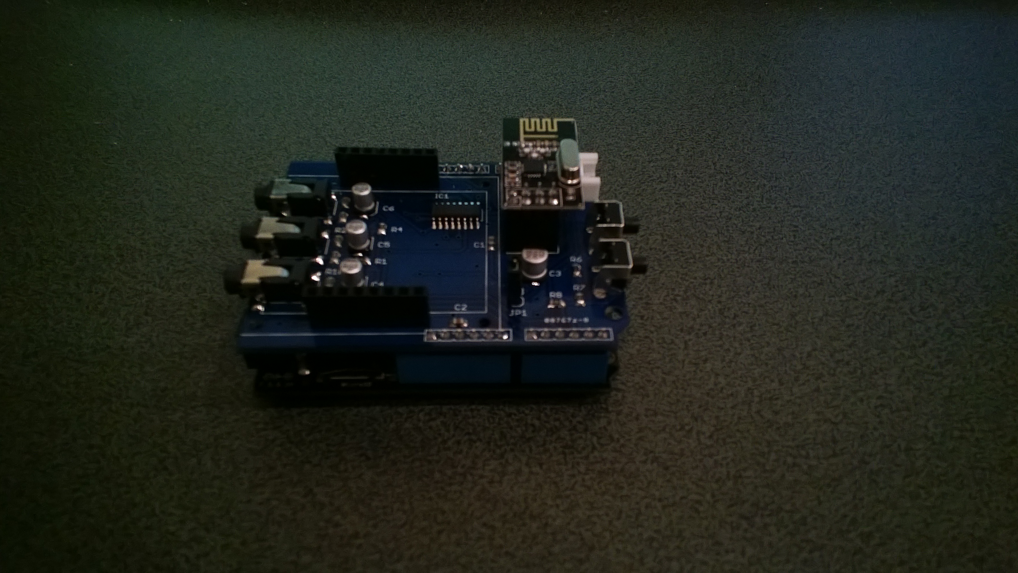
The two buttons on the energy monitor shield are connected to the analog input A3 via a voltage divider. The shield appears to be designed for 5V devices as the input for the voltage divider is connected to VCC which is 5V. Netduinos and some Arduinos are 3.3V devices and this approach won’t work on these devices.
public static void Main()

{

AnalogInput buttons = new AnalogInput(Cpu.AnalogChannel.ANALOG_3);
while (true)

{

Debug.Print(buttons.Read().ToString("F2"));

Thread.Sleep(250);

}

}
The return value of the AnalogOutput with no button pressed was 1.0, SW1 pressed 1.0 and with SW2 pressed 0.93.
To work around this issue I modified the shield so the input voltage to the voltage divider is 3.3V. With my modified shield the return value of the AnalogOutput with no button pressed was 0.87, SW1 pressed 0.83 and with SW2 pressed 0.67. [Edit-see next post with easier modification]
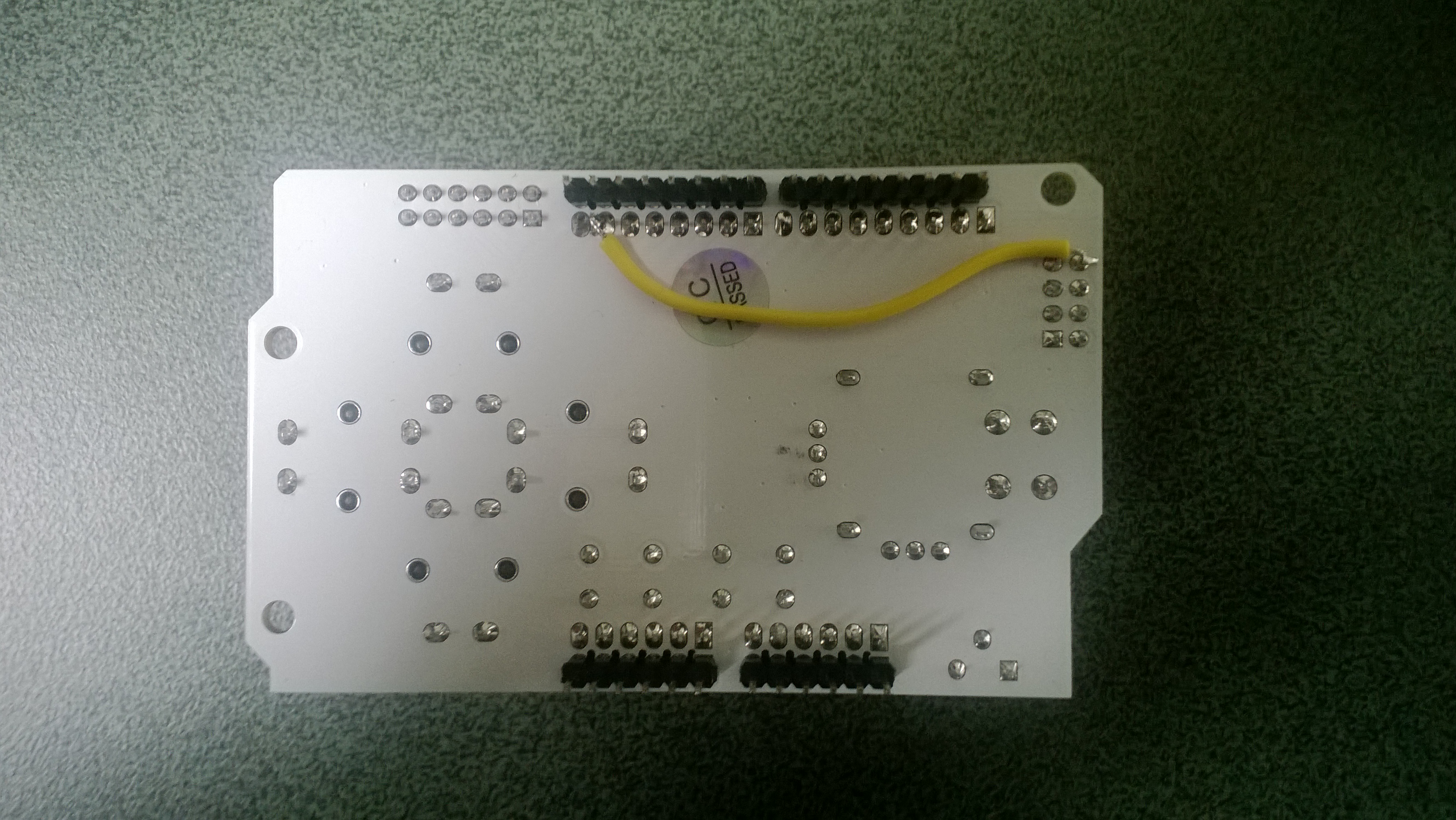
To change the input voltage of the voltage divider I removed R8(circled) and replaced it with a 1K resistor connected to 3.3V.
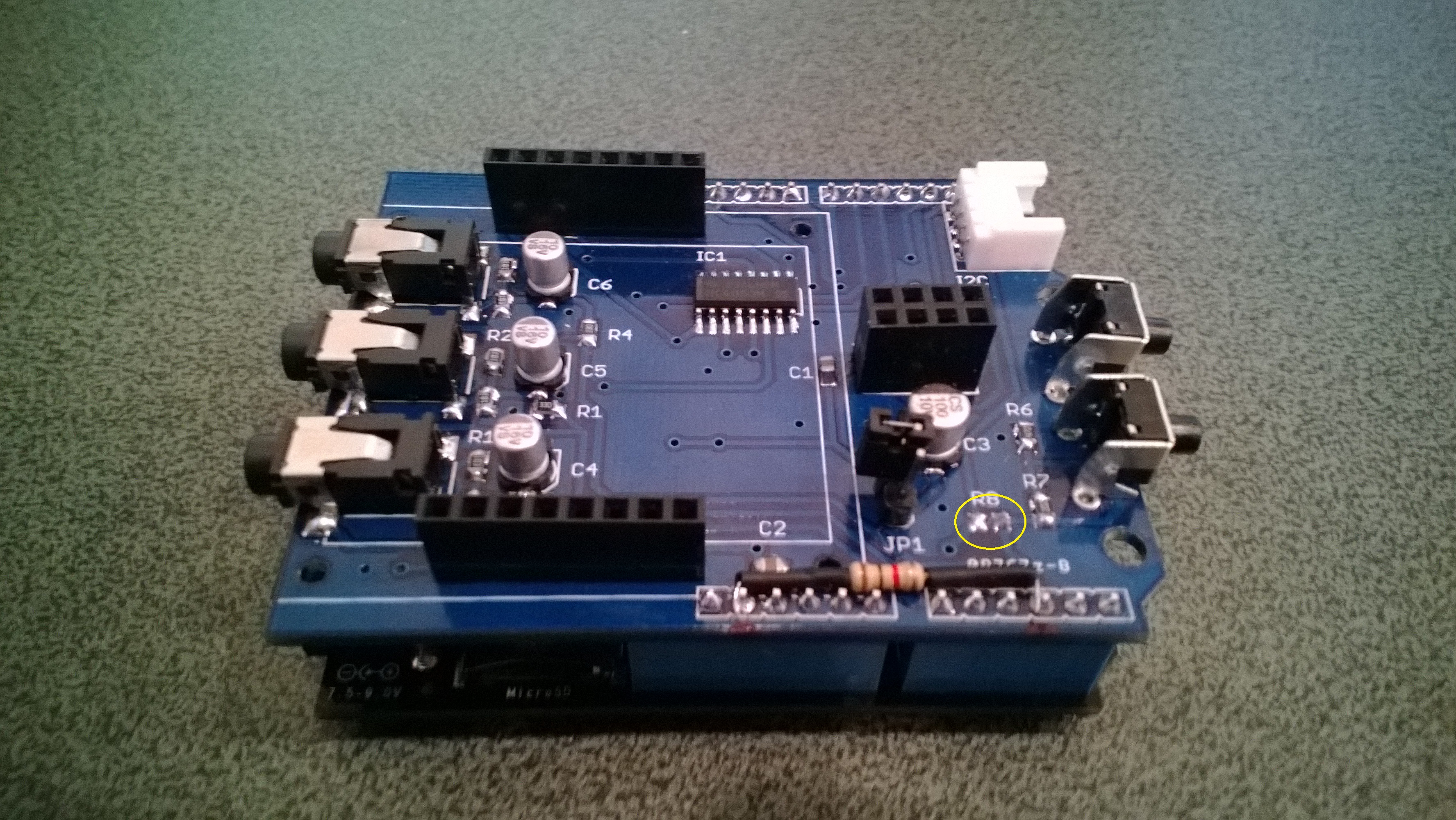
Energy Shield with Button modifications