This is the simplest .NET nanoFramework Azure IoT Hub client I could come up with (inspired by this nanoFramework sample).
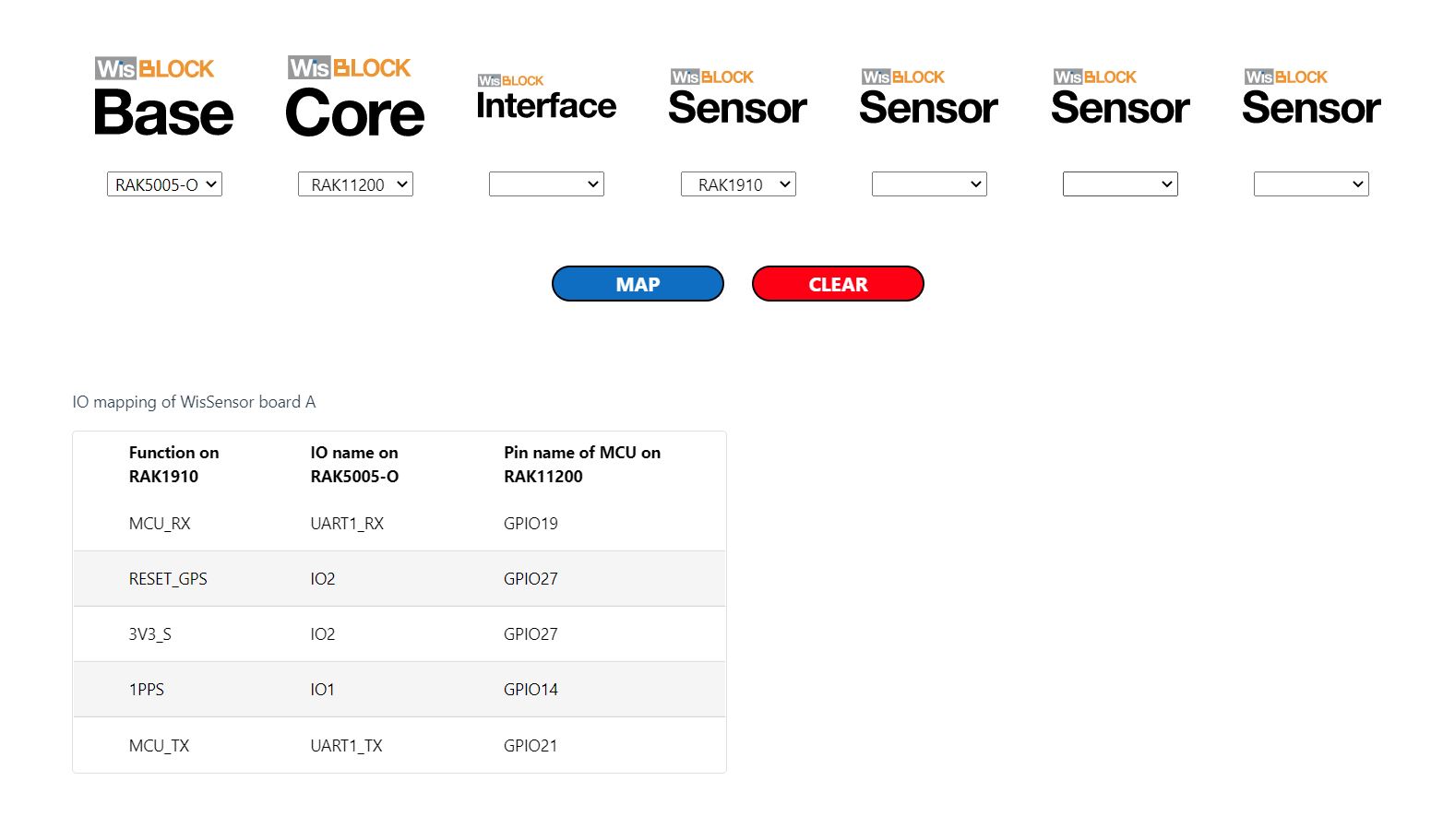
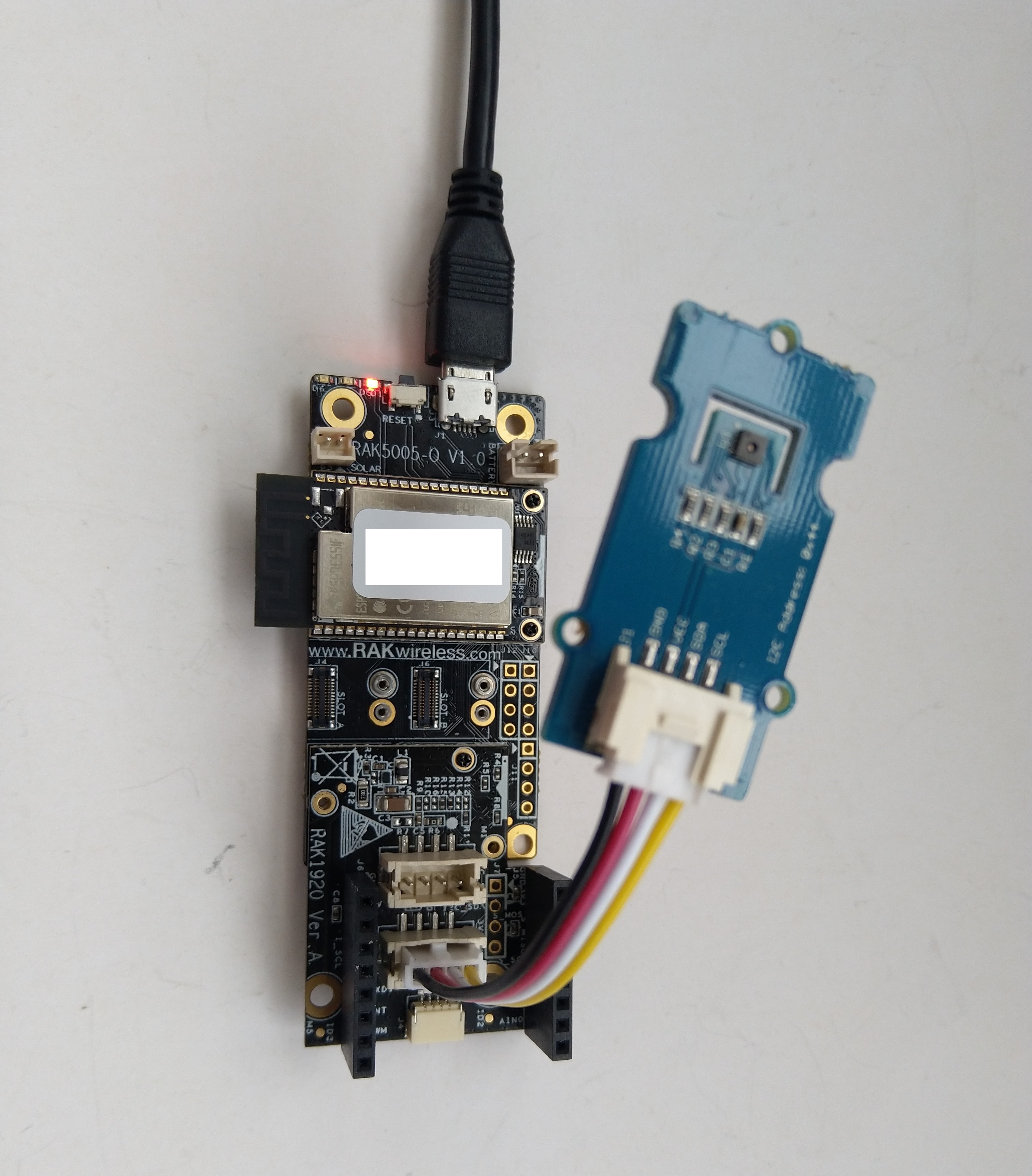
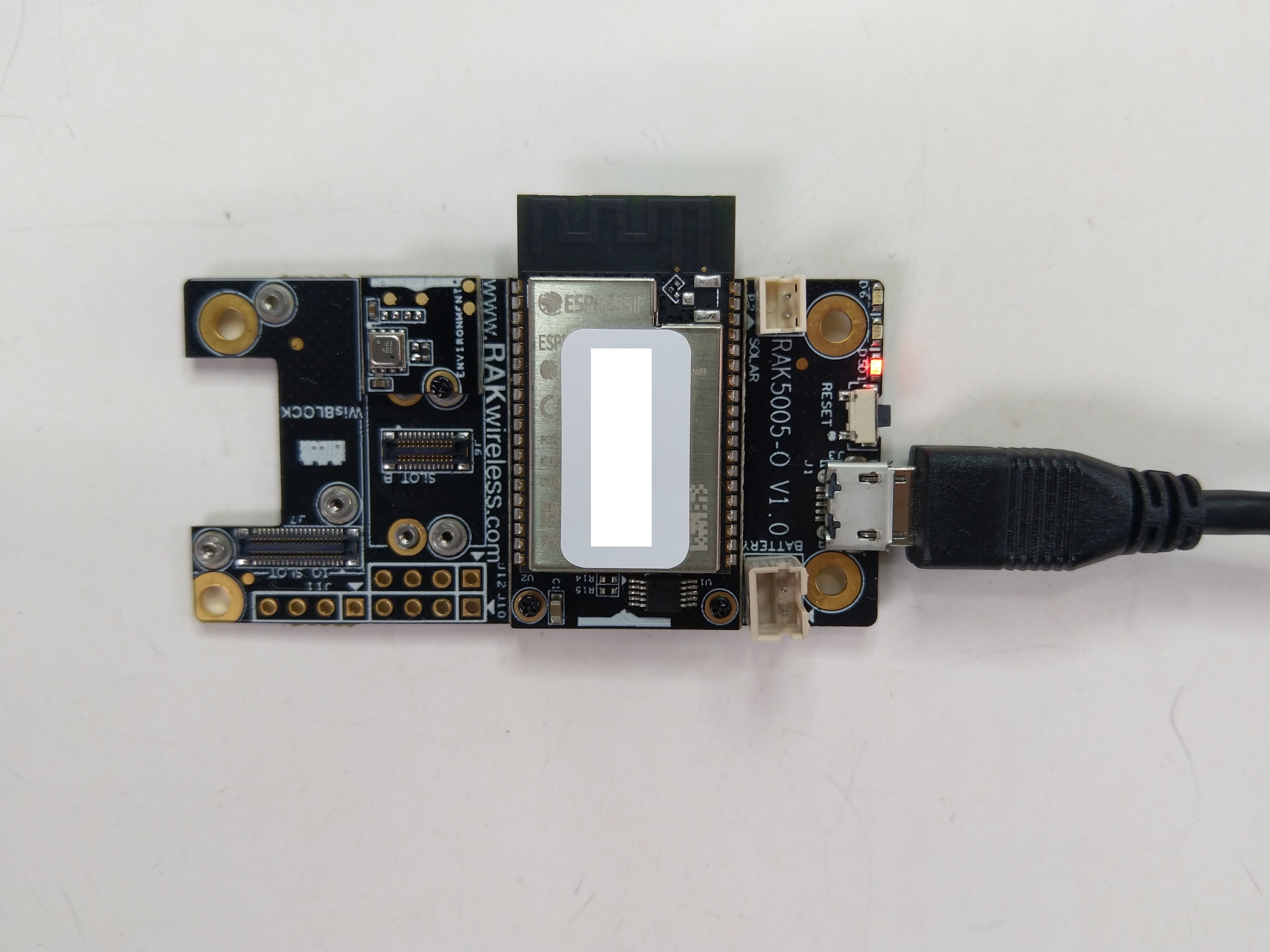
My test setup was a RAKwireless RAK11200 WisBlock WiFi Module, RAK5005 WisBlock Base Board or RAK19001 WisBlock Dual IO Base Board and RAK1901 WisBlock Temperature and Humidity Sensor


I used a RAK1901 WisBlock Temperature and Humidity Sensor because it has nanoFramework.IoTDevice library support
public class Program
{
private static TimeSpan SensorUpdatePeriod = new TimeSpan(0, 30, 0);
private static HttpClient _httpClient;
public static void Main()
{
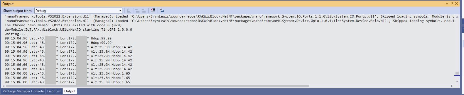
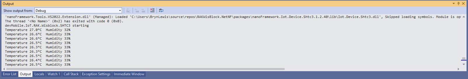
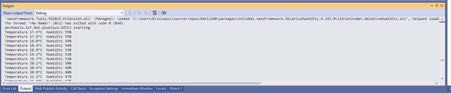
Debug.WriteLine("devMobile.IoT.RAK.Wisblock.AzureIoHub.RAK1901 starting");
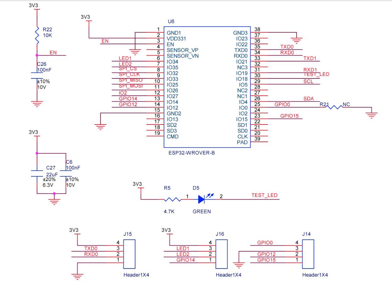
Configuration.SetPinFunction(Gpio.IO04, DeviceFunction.I2C1_DATA);
Configuration.SetPinFunction(Gpio.IO05, DeviceFunction.I2C1_CLOCK);
if (!WifiNetworkHelper.ConnectDhcp(Config.Ssid, Config.Password, requiresDateTime: true))
{
if (NetworkHelper.HelperException != null)
{
Debug.WriteLine($"WifiNetworkHelper.ConnectDhcp failed {NetworkHelper.HelperException}");
}
Thread.Sleep(Timeout.Infinite);
}
_httpClient = new HttpClient
{
SslProtocols = System.Net.Security.SslProtocols.Tls12,
HttpsAuthentCert = new X509Certificate(Config.DigiCertBaltimoreCyberTrustRoot),
BaseAddress = new Uri($"https://{Config.AzureIoTHubHostName}.azure-devices.net/devices/{Config.DeviceID}/messages/events?api-version=2020-03-13"),
};
_httpClient.DefaultRequestHeaders.Add("Authorization", Config.SasKey);
I2cConnectionSettings settings = new(1, Shtc3.DefaultI2cAddress);
I2cDevice device = I2cDevice.Create(settings);
Shtc3 shtc3 = new(device);
while (true)
{
if (shtc3.TryGetTemperatureAndHumidity(out var temperature, out var relativeHumidity))
{
Debug.WriteLine($"Temperature {temperature.DegreesCelsius:F1}°C Humidity {relativeHumidity.Value:F0}%");
string payload = $"{{\"RelativeHumidity\":{relativeHumidity.Value:F0},\"Temperature\":{temperature.DegreesCelsius.ToString("F1")}}}";
try
{
using (HttpContent content = new StringContent(payload))
using (HttpResponseMessage response = _httpClient.Post("", content))
{
Console.WriteLine($"{DateTime.UtcNow:HH:mm:ss} Response code:{response.StatusCode}");
response.EnsureSuccessStatusCode();
}
}
catch(Exception ex)
{
Debug.WriteLine($"Azure IoT Hub POST failed:{ex.Message}");
}
}
Thread.Sleep(SensorUpdatePeriod);
}
}
}
I generated the Azure IoT Hub Shared Access Signature(SAS) Tokens (10800 minutes is 1 week) with Azure IoT Explorer (Trim the SAS key so it starts with SharedAccessSignature sr=….)

I was using Azure IoT Explorer to monitor the telemetry and found that the initial versions of the application would fail after 6 or 7 hours. After reviewing the code I added a couple of “using” statements which appear to have fixed the problem as the soak test has been running for 12hrs, 24hrs, 36hrs, 48hrs, 96hrs…