Energy Monitor Shield Sensor Calibration

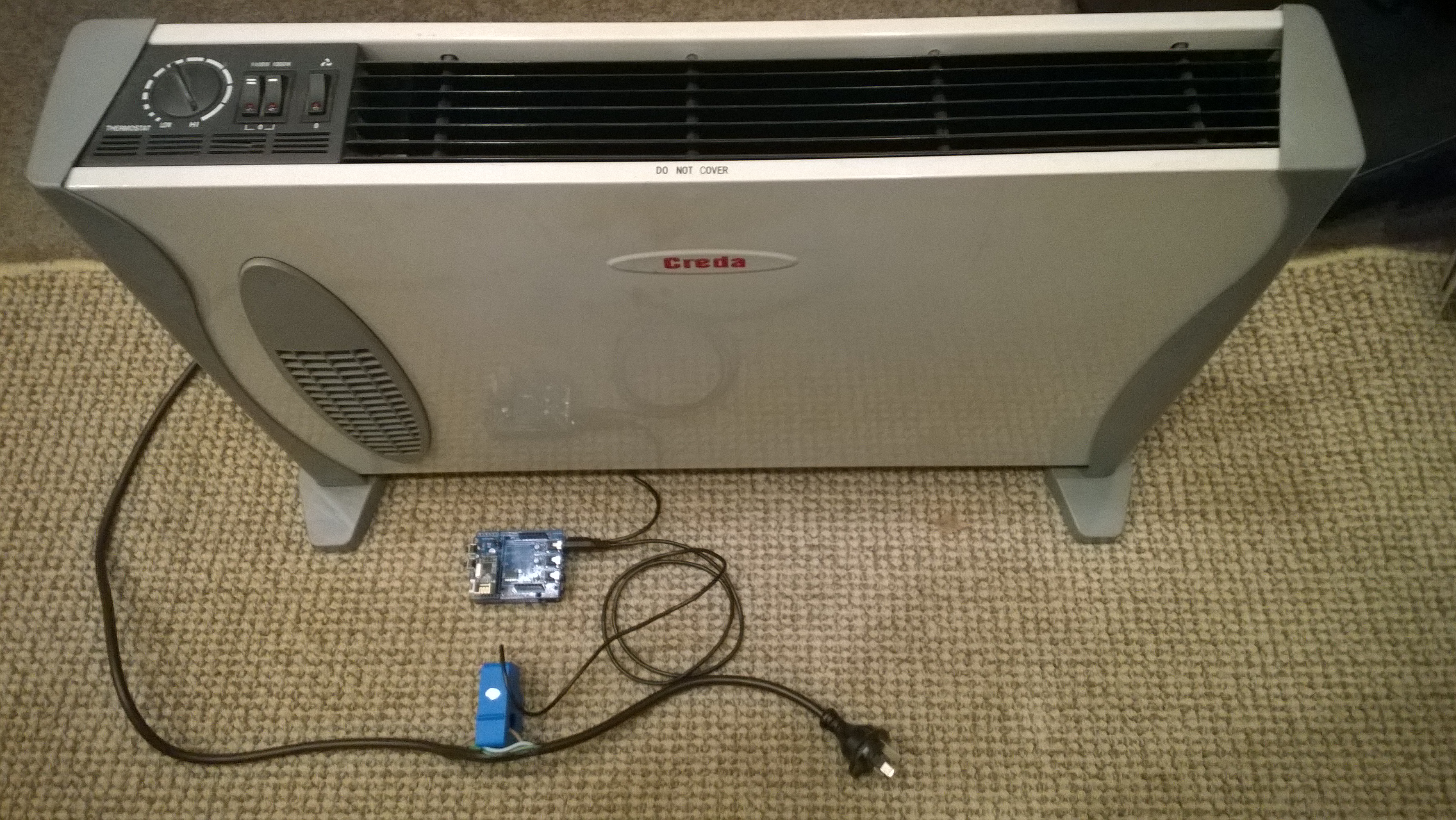
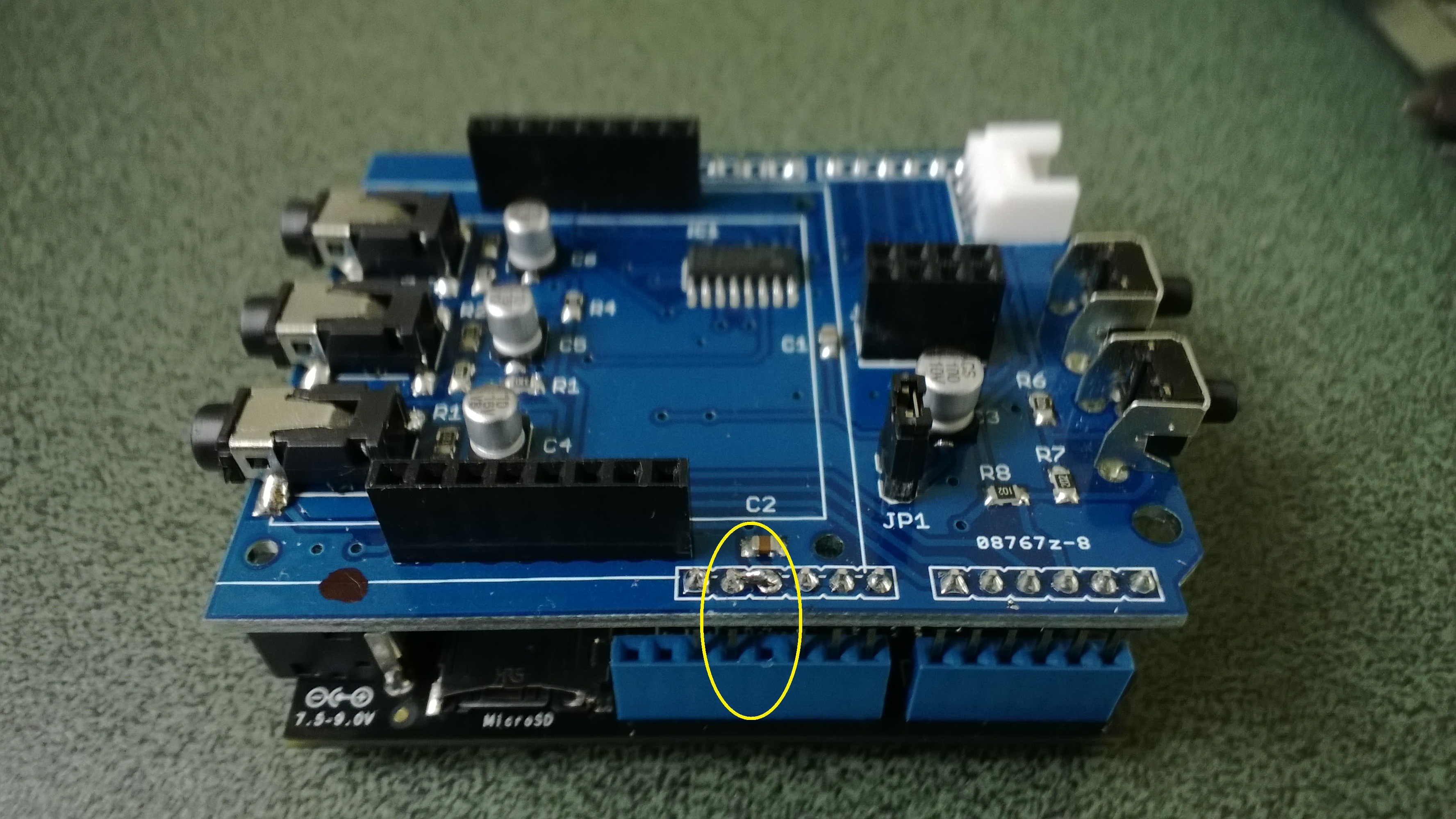
The Netduino 2 Plus AnalogInput has a range of 0V to 3V3. The Non Invasive Current Sensor we are using returns 0-1V AC for 0-30 Amps AC. To measure the sensor’s output waveform the Energy Monitor Shield uses a voltage divider to offset the reference voltage to 3v3/2. To calibrate the sensor we averaged the input voltage and over 100,000 readings.

The initial code looked like this

int value;
int valueSum = 0;
AnalogInput x1 = new AnalogInput(Cpu.AnalogChannel.ANALOG_0);

stopwatch.Start();
for (int i = 0; i < SampleCount; i++)
{
value = x1.ReadRaw();

valueSum = valueSum + value;
}
stopwatch.Stop();

Duration = 2272 mSec 44014/sec
Duration = 2273 mSec 43994/sec
Duration = 2272 mSec 44014/sec

I then modified the code to not use a temporary variable

int valueSum = 0;
AnalogInput x1 = new AnalogInput(Cpu.AnalogChannel.ANALOG_0);

stopwatch.Start();
for (int i = 0; i < SampleCount; i++)
{
valueSum = valueSum + x1.ReadRaw();
}
stopwatch.Stop();

Duration = 2181 mSec 45829/sec
Duration = 2182 mSec 45829/sec
Duration = 2181 mSec 45829/sec

The code without the temporary variable was slightly faster.


Netduino AnalogInput read rates

At CodeClub some of the students are building a netduino based power consumption monitor using an Energy Monitor Shield (with my modifications). The approach for the software was “inspired” by the Arduino code developed by the Open Energy Monitor project. First step was to confirm that the Netduino 2 Plus we were using could sample the Alternating Current(AC) waveform often enough.

The first version of the code called the Microsoft.Spot.Hardware.AnalogInput.Read method (which returns a floating point number) 100,000 times. The duration was measured using a Stopwatch class written by ChrisW of Secretlabs.

double value;
AnalogInput x1 = new AnalogInput(Cpu.AnalogChannel.ANALOG_0);

Stopwatch stopwatch = Stopwatch.StartNew();
stopwatch.Start();
for (int i = 0; i < SampleCount; i++)
{
value = x1.Read();
}
stopwatch.Stop();

Duration = 5496 mSec 18195/sec
Duration = 5497 mSec 18191/sec
Duration = 5496 mSec 18195/sec
Duration = 5497 mSec 18191/sec
Duration = 5496 mSec 18195/sec
Duration = 5497 mSec 18191/sec

The AnalogPort also has a overloaded Read method which returns an integer

int value;
AnalogInput x1 = new AnalogInput(Cpu.AnalogChannel.ANALOG_0);
stopwatch.Start();
for (int i = 0; i < SampleCount; i++)
{
value = x1.ReadRaw();
}
stopwatch.Stop();

Duration = 2081 mSec 48053/sec
Duration = 2082 mSec 48030/sec
Duration = 2081 mSec 48053/sec
Duration = 2082 mSec 48030/sec
Duration = 2081 mSec 48053/sec

There is also a Secret labs AnalogInput which has a Read method which returns an integer

int value;
SecretLabs.NETMF.Hardware.AnalogInput x1 = new SecretLabs.NETMF.Hardware.AnalogInput(Pins.GPIO_PIN_A0);
stopwatch.Start();
for (int i = 0; i < SampleCount; i++)
{
value = x1.Read();
}
stopwatch.Stop();

Duration = 8563 mSec 11678/sec
Duration = 8564 mSec 11676/sec
Duration = 8563 mSec 11678/sec

The int Microsoft.Spot.Hardware.AnalogInput.ReadRaw() appears to be  quite a bit faster than the other two approaches.

Energy Monitor Shield Sensor Box by Tardis

My initial way of connecting the current sensor for the Energy Monitor Shield was not really suitable for CodeClub. Carefully cutting the insulation with a craft knife and gently pulling out the phase wire could end really badly.

Image

I approached a local company Tardis Communications and they made Code Club these neat enclosures which ensure the students can’t come into contact with any live connections.

Image

Canterbury Software Cluster Internet of Things Presentation

For my presentation last week I prepared a sample xively and Netduino based application to illustrate what could be built with off the shelf kit. I built a wireless home monitoring system which had two energy consumption monitoring devices and a dual temperature sensor device. These devices uploaded their data using MQTT to xively in close to real time. Prices as at May 2014

The devices connected to the internet via a gateway.

Image

The software running on the Netduino was built using the NetMF library from KittyHawkMQ and the nRF24L01+ library from codeplex

Testing the solar powered temperature sensor monitoring my kitchen fridge. The fridge was 4° and the freezer was -18°

Image

The software was based on the nRF24L01library on codeplex,  Brad’s One-Wire and DS18B20 library with fixes from here.

Testing the power consumption monitor devices, with my “modified” power lead.

Image

The software was based on the approach in the Arduino code of the emon libraries from the Open Energy Monitor project which I’ll discuss in more detail in a future post.

Freaduino MP3 Music Shield

For code club one of the projects I had been considering was an MP3 player with a simple user interface (UI) based on a joystick providing track next/previous , volume up/down, and pause/play. I looked for suitable Arduino shields which had Netduino driver support. I narrowed the list down to (Prices as at April 2014) these VS1053 based shields

For Code Club I purchased 5 of the Elecfreaks Freaduino shields as the price and on-board joystick made it ideal for our application. The Freaduino MP3 Shield wiki page indicated that the following pins were used by the SPI bus

D10 – Used for SPI Chip Select.
D11 – Used for SPI MOSI.
D12 – Used for SPI MISO.
D13 – Used for SPI SCK.

I initially tried the NetduinoVS1053 library from SoftElectoTech but found that no sound was produced. I tried different pin configurations, format and bitrate music files but nothing worked. I then had a look at the shield schematic and noticed that D11/D12/D13 were not connected to the VS1053, only D10 which is used for chip selected on the MicroSD card socket was connected.

I soldered some jumpers to the board and connected the SPI pins on the ICSP socket to the D11,D12 & D13 on the edge connector and the shield now works. It would be good if elecfreaks could make the pins the SPI bus uses configurable using jumpers or similar.

Modified Freaduino Music Shield

Modified Freaduino Music Shield

The library needs to be initialised with the following pins

Player = newVs1053B(Pins.GPIO_PIN_A1, Pins.GPIO_PIN_A3, Pins.GPIO_PIN_A2, Pins.GPIO_PIN_A0);

The joystick operations can be handled with Interrupts with the following configuration

InterruptPort volumeDownButton = newInterruptPort(Pins.GPIO_PIN_D7, false, Port.ResistorMode.PullUp, Port.InterruptMode.InterruptEdgeLow);

InterruptPort volumeUpButton = newInterruptPort(Pins.GPIO_PIN_D3, false, Port.ResistorMode.PullUp, Port.InterruptMode.InterruptEdgeLow);

InterruptPort nextSongButton = newInterruptPort(Pins.GPIO_PIN_D4, false, Port.ResistorMode.PullUp, Port.InterruptMode.InterruptEdgeLow);

InterruptPort previousSongButton = newInterruptPort(Pins.GPIO_PIN_D6, false, Port.ResistorMode.PullUp, Port.InterruptMode.InterruptEdgeLow);

InterruptPort playStopButton = newInterruptPort(Pins.GPIO_PIN_D5, false, Port.ResistorMode.PullUp, Port.InterruptMode.InterruptEdgeLow);

volumeUpButton.OnInterrupt += new NativeEventHandler(volumeUpButton_OnInterrupt);

volumeDownButton.OnInterrupt += new NativeEventHandler(volumeDownButton_OnInterrupt);

nextSongButton.OnInterrupt += new NativeEventHandler(nextSongButton_OnInterrupt);

previousSongButton.OnInterrupt += new NativeEventHandler(previousSongButton_OnInterrupt);

playStopButton.OnInterrupt += new NativeEventHandler(playStopButton_OnInterrupt);

I could now play MP3 files off the SD card on my Netduino Plus 2 but couldn’t adjust the volume or change the track being played. Using an interrupt based approached for the UI also highlighted some problems with the driver code which I will discuss in a future post.

Ultrasonic Ranger Distance Measurement

I had been thinking about an Ultrasonic Tape measure as one of the projects for code club. One of the “challenges” we start each evening with was measuring how long the Netduino on board button was pressed using an InterruptPort triggering on both the leading and trailing edges. This challenge implements the core of the code required to use an Ultrasonic Ranger.

Ultrasonic Ranger connected to Netduino Plus 2

Ultrasonic Ranger Test Rig bill of Materials (April 2014)

A plug and play option would be

To make a measurement the trigger pin is strobed high, then the duration of the pulse on the echo pin represents the distance from the object. The NetMF DataTime structure represents tick as one hundred nanoseconds or one ten-millionth of a second. (There are 10,000 ticks in a millisecond) so the duration in ticks/58 is the distance in millimetres.

public UltraSonicRanger(Cpu.Pin triggerPin, Cpu.Pin echoPin)
{
   #region Diagnostic Assertions
   Debug.Assert(echoPin != Cpu.Pin.GPIO_NONE);
   Debug.Assert(triggerPin != Cpu.Pin.GPIO_NONE);
   Debug.Assert(echoPin != triggerPin);
   #endregion

   triggerOutput = new OutputPort(triggerPin, false);

   echoInterrupt = new InterruptPort(echoPin, true, Port.ResistorMode.Disabled, Port.InterruptMode.InterruptEdgeBoth);
   echoInterrupt.OnInterrupt += new NativeEventHandler(echoInterruptPort_OnInterrupt);
   echoInterrupt.DisableInterrupt();
}

void echoInterruptPort_OnInterrupt(uint data1, uint data2, DateTime time)
{
   if (data2 == 0) // falling edge, end of pulse
   {
      pulseWidthTicks = time.Ticks - pulseStartTicks;
      measurementComplete.Set();
   }
   else
   {
      pulseStartTicks = time.Ticks;
   }
}

Ultrasonic Ranger module source

I was pleasantly surprised by the sub 0.5 cm accuracy of the sensor

Energy Monitor Shield Current Sensor

The energy monitor shield has three current sensor inputs (A0 thru A2) which have a voltage divider to provide a reference offset voltage for the analog inputs on the Netduino. The reference offset voltage with a 5V supply was 2.5V which meant on a 3.3V device the range of the sensors (1V for 30 Amps) would be compromised.

In a previous post I modified the shield by replacing a resistor but there appears to be an easier modification. While looking at the schematic and the shield I realised that cutting off the 5V pin and connecting the 3.3V pin and 5V pin together would make all the analog inputs use the 3.3V rail.

Energy Shield with modifications for 3.3V operation

Energy Shield with modifications for 3.3V operation

It would be good if the designers of the shield would consider putting a switch or jumpers on the device to allow 3V3 or 5V operation.

public class Program
{
public static void Main()
{
AnalogInput buttons = new AnalogInput(Cpu.AnalogChannel.ANALOG_0);

while (true)
{
Debug.Print(buttons.Read().ToString(“F2”));

Thread.Sleep(250);
}
}
}

Energy Monitor Shield Buttons

The two buttons on the energy monitor shield are connected to the analog input A3 via a voltage divider. The shield appears to be designed for 5V devices as the input for the voltage divider is connected to VCC which is 5V. Netduinos and some Arduinos are 3.3V devices and this approach won’t work on these devices.

public static void Main()
{
AnalogInput buttons = new AnalogInput(Cpu.AnalogChannel.ANALOG_3);


while (true)
{
Debug.Print(buttons.Read().ToString("F2"));
Thread.Sleep(250);
}
}

The return value of the AnalogOutput with no button pressed was 1.0, SW1 pressed 1.0 and with SW2 pressed 0.93.

To work around this issue I modified the shield so the input voltage to the voltage divider is 3.3V. With my modified shield the return value of the AnalogOutput with no button pressed was 0.87, SW1 pressed 0.83 and with SW2 pressed 0.67. [Edit-see next post with easier modification]

To change the input voltage of the voltage divider I removed R8(circled) and replaced it with a 1K resistor connected to 3.3V.

Energy Shield with Button modifications

Energy Shield with Button modifications


Energy Monitor Shield nRF24L01+

The nRF24L01 functionality looked like a good place to start so I had a look at the documentation. The interface for connecting the nRF24L01+ module was specified as

D11 – MOSI
D12 – MISO
D13 – SCK
D8 – RF_CE
D7 – RF_CSN
D2 – RF_IRQ

I have used the Nordic nRF240L1+ .Net Micro Framework Driver on a couple of other projects but initially struggled to get it working with this configuration. After looking at the pin outs of the nRF24L01+ and the Energy Monitor Shield schematic I think the CSN & CE are reversed.(as at March 2014).

This code works and was adapted from the sample application provided with the driver on codeplex

public class nRF240l1Module
{
private const byte channel = 10;
private readonly OutputPort _led = new OutputPort(Pins.ONBOARD_LED, false);
private readonly NRF24L01Plus _module;
private Timer _timer;
private byte _token;

private readonly byte[] _myAddress = Encoding.UTF8.GetBytes(“NetP1”);
//private readonly byte[] _myAddress = Encoding.UTF8.GetBytes(“NetP2”);
private readonly byte[] _otherBoard = Encoding.UTF8.GetBytes(“NetP2”);
//private readonly byte[] _otherBoard = Encoding.UTF8.GetBytes(“NetP1”);

public nRF240l1Module()
{
_module = new NRF24L01Plus();
}

public void Run()
{
_module.OnDataReceived += OnReceive;
_module.OnTransmitFailed += OnSendFailure;
_module.OnTransmitSuccess += OnSendSuccess;

_module.Initialize(SPI.SPI_module.SPI1, Pins.GPIO_PIN_D8, Pins.GPIO_PIN_D7, Pins.GPIO_PIN_D2);
_module.Configure(_myAddress, channel, NRFDataRate.DR250kbps);
_module.Enable();

_timer = new Timer(SendMessage, null, new TimeSpan(0, 0, 0, 1), new TimeSpan(0, 0, 0, 1));
}

private void OnSendSuccess()
{
_led.Write(false);
}

private void OnSendFailure()
{
Debug.Print(“Send failed!”);
}

private void OnReceive(byte[] data)
{
Debug.Print(“Token <- ” + data[0]);
}

private void SendMessage(object state)
{
_led.Write(true);
_module.SendTo(_otherBoard, new[] { _token });
Debug.Print(“Token -> ” + _token);
_token++;
}

}

Energy Shield with nRF24L01Plus

Energy Shield with nRF24L01Plus

Energy Monitor Shield arrived

One of the projects I’m planning for code club is a power consumption monitor. After some research and checking of circuit diagrams the Energy Monitor Shield designed by devicter looked like it would work with a Netduino. The analog voltage inputs for the AC current sensors plus the SPI bus configuration for the Nokia 5110 display and nRF24L01+ appear to be compatible.

Image

Initial impressions are good, only problem is the backlight is a little bit bright (so I removed the jumper).