TinyCLR OS LoRa library Part1

After writing my Windows 10 IoT Core RFM9X library and porting it to .NetMF and Wilderness Labs Meadow I figured another port to GHI Electronics TinyCLR-OS on a FEZ device shouldn’t take too long.

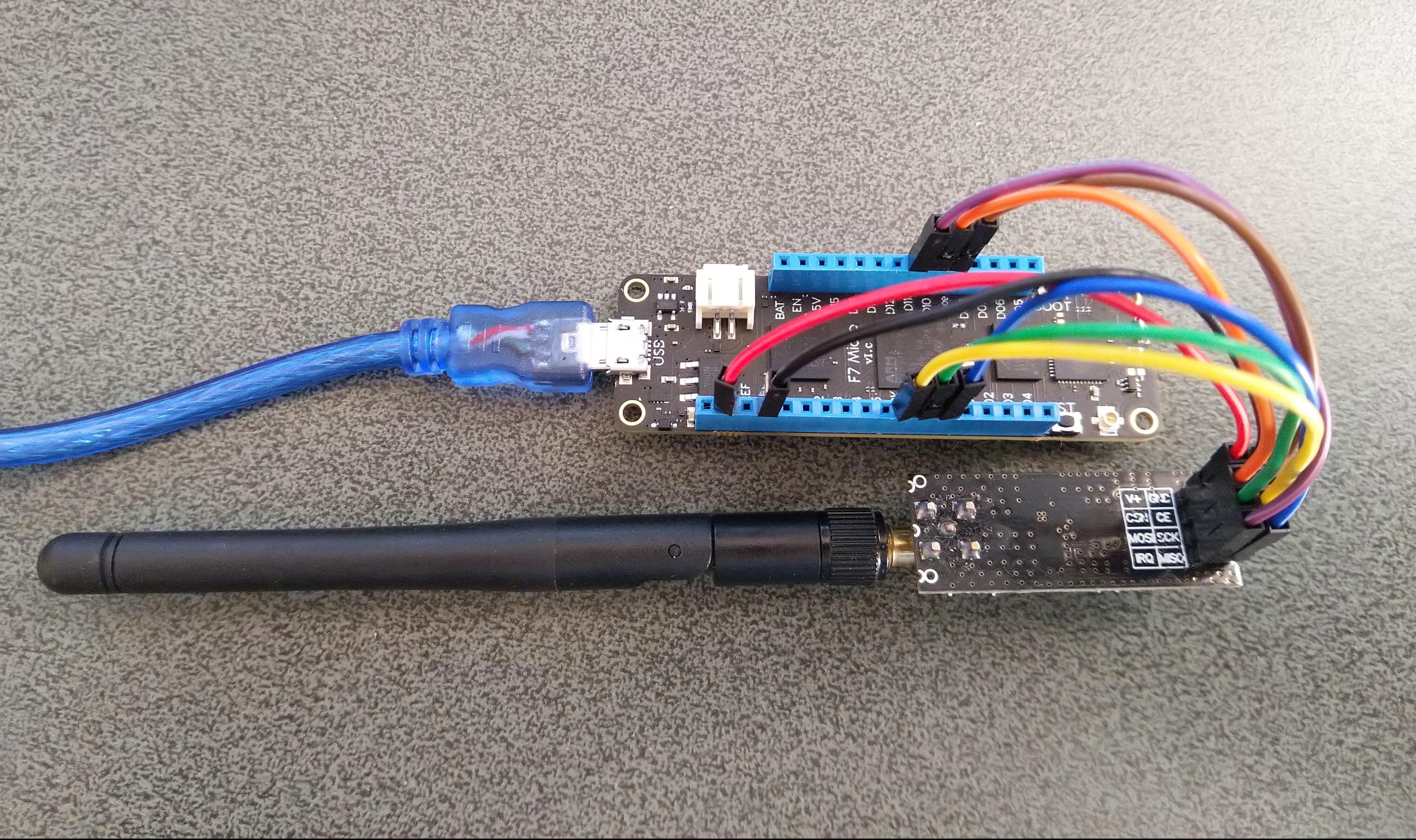
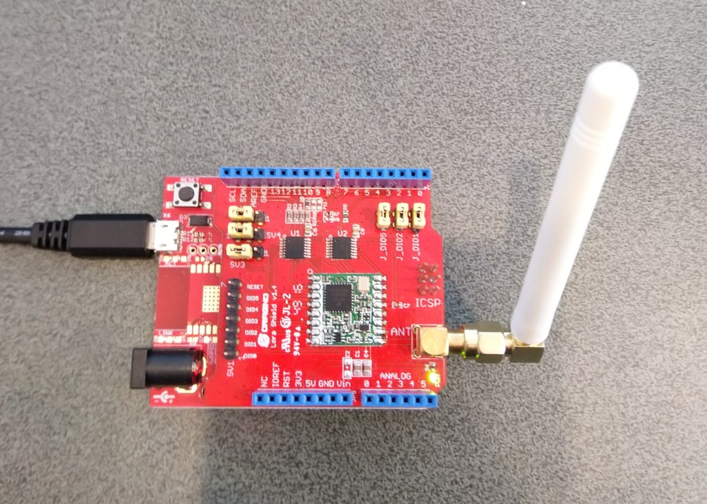
To get started I used a Dragino LoRa shield for Arduino which looked compatible with my FEZT18-N and FEZT18-W devices.

Dragino Arduino LoRa Shield Schematic

The shield uses D10 for chip select, D2 for RFM9X DI0 interrupt and D9 for Reset. The shield ships with the SPI lines configured for ICSP so the three jumpers diagonally across the shield from the antenna connector need to be swapped to the side closest to the edge of the shield.

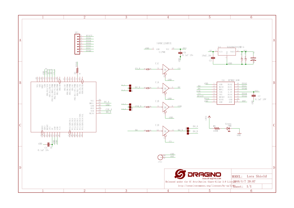
First step was to confirm I could (using the TinyCLR SPI NuGet library) read a couple of the Semtech SX1276 registers.

//---------------------------------------------------------------------------------
// Copyright (c) March 2020, devMobile Software
//
// Licensed under the Apache License, Version 2.0 (the "License");
// you may not use this file except in compliance with the License.
// You may obtain a copy of the License at
//
//     http://www.apache.org/licenses/LICENSE-2.0
//
// Unless required by applicable law or agreed to in writing, software
// distributed under the License is distributed on an "AS IS" BASIS,
// WITHOUT WARRANTIES OR CONDITIONS OF ANY KIND, either express or implied.
// See the License for the specific language governing permissions and
// limitations under the License.
//
//---------------------------------------------------------------------------------
namespace devMobile.IoT.Rfm9x.ShieldSpi
{
   using System;
   using System.Diagnostics;

   using System.Threading;
   using GHIElectronics.TinyCLR.Devices.Spi;
   using GHIElectronics.TinyCLR.Pins;

   class Program
   {
      static void Main()
      {
         var settings = new SpiConnectionSettings()
         {
            ChipSelectType = SpiChipSelectType.Gpio,
            ChipSelectLine = FEZ.GpioPin.D10,
            Mode = SpiMode.Mode0,
            ClockFrequency = 500000,
            DataBitLength = 8,
            ChipSelectActiveState = false,
         };

         var controller = SpiController.FromName(FEZ.SpiBus.Spi1);
         var device = controller.GetDevice(settings);

         Thread.Sleep(500);

         while (true)
         {
            byte register;
            byte[] writeBuffer;
            byte[] readBuffer;

            // Silicon Version info
            register = 0x42; // RegVersion expecting 0x12

            // Frequency
            //register = 0x06; // RegFrfMsb expecting 0x6C
            //register = 0x07; // RegFrfMid expecting 0x80
            //register = 0x08; // RegFrfLsb expecting 0x00

            //register = 0x17; //RegPayoadLength expecting 0x47

            // Preamble length 
            //register = 0x18; // RegPreambleMsb expecting 0x32
            //register = 0x19; // RegPreambleLsb expecting 0x3E

            writeBuffer = new byte[] { register,  0x0 };
            readBuffer = new byte[writeBuffer.Length];

            device.TransferFullDuplex(writeBuffer, readBuffer);

            Debug.WriteLine("Value = 0x" + BytesToHexString(readBuffer));

            Thread.Sleep(1000);
         }
      }

      private static string BytesToHexString(byte[] bytes)
      {
         string hexString = string.Empty;

         // Create a character array for hexidecimal conversion.
         const string hexChars = "0123456789ABCDEF";

         // Loop through the bytes.
         for (byte b = 0; b < bytes.Length; b++)
         {
            if (b > 0)
               hexString += "-";

            // Grab the top 4 bits and append the hex equivalent to the return string.        
            hexString += hexChars[bytes[b] >> 4];

            // Mask off the upper 4 bits to get the rest of it.
            hexString += hexChars[bytes[b] & 0x0F];
         }

         return hexString;
      }
   }
}

After trying many permutations of settings I could successfully read the RegVersion and default frequency values

The debugging target runtime is loading the application assemblies and starting execution.
Ready.

'GHIElectronics.TinyCLR.VisualStudio.ProjectSystem.dll' (Managed): Loaded 'C:\Users\BrynLewis\source\repos\RFM9X.TinyCLR\ShieldSPI\bin\Debug\pe\..\GHIElectronics.TinyCLR.Native.dll'
'GHIElectronics.TinyCLR.VisualStudio.ProjectSystem.dll' (Managed): Loaded 'C:\Users\BrynLewis\source\repos\RFM9X.TinyCLR\ShieldSPI\bin\Debug\pe\..\GHIElectronics.TinyCLR.Devices.Gpio.dll'
'GHIElectronics.TinyCLR.VisualStudio.ProjectSystem.dll' (Managed): Loaded 'C:\Users\BrynLewis\source\repos\RFM9X.TinyCLR\ShieldSPI\bin\Debug\pe\..\GHIElectronics.TinyCLR.Devices.Spi.dll'
'GHIElectronics.TinyCLR.VisualStudio.ProjectSystem.dll' (Managed): Loaded 'C:\Users\BrynLewis\source\repos\RFM9X.TinyCLR\ShieldSPI\bin\Debug\pe\..\ShieldSPI.exe', Symbols loaded.
The thread '<No Name>' (0x2) has exited with code 0 (0x0).
Value = 0x00-12
Value = 0x00-12
Value = 0x00-12
Value = 0x00-12

Overall the SPI implementation felt closer to Windows 10 IoT Core model than expected.

.Net Meadow nRF24L01 library Part3

While testing my initial port of the the techfooninja nRF24L01P library to a Wilderness Labs Meadow I noticed that the power level value was a bit odd.

nRF24L01P Test Harness
The program '[16720] App.exe' has exited with code 0 (0x0).
 IsPowered: True
 Address: Dev01
 PA: 15
 IsAutoAcknowledge: True
 Channel: 15
 DataRate: DR250Kbps
 Power: 15
 IsDynamicAcknowledge: False
 IsDynamicPayload: True
 IsEnabled: False
 Frequency: 2415
 IsInitialized: True
 IsPowered: True
 00:00:18-TX 8 byte message hello 17
 Data Sent!
00:00:18-TX Succeeded!
 00:00:48-TX 8 byte message hello 48
 Data Sent!

Looking at nRF24L01P datasheet and how this has been translated into code

/// <summary>
///   The power level for the radio.
/// </summary>
public PowerLevel PowerLevel
{
  get
   {
      var regValue = Execute(Commands.R_REGISTER, Registers.RF_SETUP, new byte[1])[1] & 0xF8;
      var newValue = (regValue - 1) >> 1;
      return (PowerLevel)newValue;
   }
  set
   {
      var regValue = Execute(Commands.R_REGISTER, Registers.RF_SETUP, new byte[1])[1] & 0xF8;

      byte newValue = (byte)((byte)value << 1 + 1);

      Execute(Commands.W_REGISTER, Registers.RF_SETUP,
              new[]
                  {
                     (byte) (newValue | regValue)
                  });
   }
}

The power level enumeration is declared in PowerLevel.cs

namespace Radios.RF24
{
    /// <summary>
    ///   Power levels the radio can operate with
    /// </summary>
    public enum PowerLevel : byte
    {
        /// <summary>
        ///   Minimum power setting for the radio
        /// </summary>
        Minimum = 0,

        /// <summary>
        ///   Low power setting for the radio
        /// </summary>
        Low,

        /// <summary>
        ///   High power setting for the radio
        /// </summary>
        High,

        /// <summary>
        ///   Max power setting for the radio
        /// </summary>
        Max,

        /// <summary>
        ///   Error with the power setting
        /// </summary>
        Error
    }
}

No debugging support or Debug.WriteLine in beta 3.7 (March 2020) so first step was to insert a Console.Writeline so I could see what the RF_SETUP register value was.

The program '[11212] App.exe' has exited with code 0 (0x0).
 Address: Dev01
 PowerLevel regValue 00100101
 PowerLevel: 15
 IsAutoAcknowledge: True
 Channel: 15
 DataRate: DR250Kbps
 IsDynamicAcknowledge: False
 IsDynamicPayload: True
 IsEnabled: False
 Frequency: 2415
 IsInitialized: True
 IsPowered: True
 00:00:18-TX 8 byte message hello 17
 Data Sent!
00:00:18-TX Succeeded!

The PowerLevel setting appeared to make no difference and the bits 5, 2 & 0 were set which meant 250Kbps & high power which I was expecting.

The RF_SETUP register in the datasheet, contains the following settings (WARNING – some nRF24L01 registers differ from nRF24L01P)

After looking at the code my initial “quick n dirty” fix was to mask out the existing power level bits and then mask in the new setting.

public PowerLevel PowerLevel
      {
         get
         {
            byte regValue = Execute(Commands.R_REGISTER, Registers.RF_SETUP, new byte[1])[1];;
            Console.WriteLine($"PowerLevel regValue {Convert.ToString(regValue, 2).PadLeft(8, '0')}");
            var newValue = (regValue & 0x06) >> 1;
            
            return (PowerLevel)newValue;
         }
         set
         {
            byte regValue = Execute(Commands.R_REGISTER, Registers.RF_SETUP, new byte[1])[1];
            regValue &= 0b11111000;
            regValue |= (byte)((byte)value << 1);

            Execute(Commands.W_REGISTER, Registers.RF_SETUP,
                    new[]
                        {
                            (byte)regValue
                        });
         }
      }

I wonder if the code mighty be simpler if I used a similar approach to my Windows 10 IoT RFM9X LoRa library

// RegModemConfig1
public enum RegModemConfigBandwidth : byte
{
	_7_8KHz = 0b00000000,
	_10_4KHz = 0b00010000,
	_15_6KHz = 0b00100000,
	_20_8KHz = 0b00110000,
	_31_25KHz = 0b01000000,
	_41_7KHz = 0b01010000,
	_62_5KHz = 0b01100000,
	_125KHz = 0b01110000,
	_250KHz = 0b10000000,
	_500KHz = 0b10010000
}
public const RegModemConfigBandwidth RegModemConfigBandwidthDefault = RegModemConfigBandwidth._125KHz;

...

[Flags]
enum RegIrqFlagsMask : byte
{
	RxTimeoutMask = 0b10000000,
	RxDoneMask = 0b01000000,
	PayLoadCrcErrorMask = 0b00100000,
	ValidHeadrerMask = 0b00010000,
	TxDoneMask = 0b00001000,
	CadDoneMask = 0b00000100,
	FhssChangeChannelMask = 0b00000010,
	CadDetectedMask = 0b00000001,
}

[Flags]
enum RegIrqFlags : byte
{
	RxTimeout = 0b10000000,
	RxDone = 0b01000000,
	PayLoadCrcError = 0b00100000,
	ValidHeadrer = 0b00010000,
	TxDone = 0b00001000,
	CadDone = 0b00000100,
	FhssChangeChannel = 0b00000010,
	CadDetected = 0b00000001,
	ClearAll = 0b11111111,
}

This would require some significant modifications to the Techfooninja library. e.g. the PowerLevel enumeration

namespace Radios.RF24
{
    /// <summary>
    ///   Power levels the radio can operate with
    /// </summary>
    public enum PowerLevel : byte
    {
        /// <summary>
        ///   Minimum power setting for the radio
        /// </summary>
        Minimum = 0b00000000,

        /// <summary>
        ///   Low power setting for the radio
        /// </summary>
        Low = 0b00000010,

        /// <summary>
        ///   High power setting for the radio
        /// </summary>
        High = 0b00000100,

        /// <summary>
        ///   Max power setting for the radio
        /// </summary>
        Max = 0b00000110,
    }
}

I need to do some more testing of the of library to see if the pattern is repeated.

Wilderness Labs nRF24L01 Wireless field gateway Meadow client

After a longish pause in development work on my nrf24L01 AdaFruit.IO and Azure IOT Hub field gateways I figured a client based on my port of the techfooninja nRF24 library to Wilderness Labs Meadow would be a good test.

This sample client is an Wilderness Labs Meadow with a Sensiron SHT31 Temperature & humidity sensor (supported by meadow foundation), and a generic nRF24L01 device connected with jumper cables.

Bill of materials (prices as at March 2020)

  • Wilderness Labs Meadow 7F Micro device USD50
  • Seeedstudio Temperature and Humidity Sensor(SHT31) USD11.90
  • Seeedstudio 4 pin Male Jumper to Grove 4 pin Conversion Cable USD2.90
  • 2.4G Wireless Module nRF24L01+PA USD9.90

The initial version of the code was pretty basic with limited error handling and no power conservation support.

namespace devMobile.IoT.FieldGateway.Client
{
   using System;
   using System.Text;
   using System.Threading;

   using Radios.RF24;

   using Meadow;
   using Meadow.Devices;
   using Meadow.Foundation.Leds;
   using Meadow.Foundation.Sensors.Atmospheric;
   using Meadow.Hardware;
   using Meadow.Peripherals.Leds;

   public class MeadowClient : App<F7Micro, MeadowClient>
   {
      private const string BaseStationAddress = "Base1";
      private const string DeviceAddress = "WLAB1";
      private const byte nRF24Channel = 15;
      private RF24 Radio = new RF24();
      private readonly TimeSpan periodTime = new TimeSpan(0, 0, 60);
      private readonly Sht31D sensor;
      private readonly ILed Led;

      public MeadowClient()
      {
         Led = new Led(Device, Device.Pins.OnboardLedGreen);

         try
         {
            sensor = new Sht31D(Device.CreateI2cBus());

            var config = new Meadow.Hardware.SpiClockConfiguration(
                           2000,
                           SpiClockConfiguration.Mode.Mode0);

            ISpiBus spiBus = Device.CreateSpiBus(
               Device.Pins.SCK,
               Device.Pins.MOSI,
               Device.Pins.MISO, config);

            Radio.OnDataReceived += Radio_OnDataReceived;
            Radio.OnTransmitFailed += Radio_OnTransmitFailed;
            Radio.OnTransmitSuccess += Radio_OnTransmitSuccess;

            Radio.Initialize(Device, spiBus, Device.Pins.D09, Device.Pins.D10, Device.Pins.D11);
            //Radio.Address = Encoding.UTF8.GetBytes(Environment.MachineName);
            Radio.Address = Encoding.UTF8.GetBytes(DeviceAddress);

            Radio.Channel = nRF24Channel;
            Radio.PowerLevel = PowerLevel.Low;
            Radio.DataRate = DataRate.DR250Kbps;
            Radio.IsEnabled = true;

            Radio.IsAutoAcknowledge = true;
            Radio.IsDyanmicAcknowledge = false;
            Radio.IsDynamicPayload = true;

            Console.WriteLine($"Address: {Encoding.UTF8.GetString(Radio.Address)}");
            Console.WriteLine($"PowerLevel: {Radio.PowerLevel}");
            Console.WriteLine($"IsAutoAcknowledge: {Radio.IsAutoAcknowledge}");
            Console.WriteLine($"Channel: {Radio.Channel}");
            Console.WriteLine($"DataRate: {Radio.DataRate}");
            Console.WriteLine($"IsDynamicAcknowledge: {Radio.IsDyanmicAcknowledge}");
            Console.WriteLine($"IsDynamicPayload: {Radio.IsDynamicPayload}");
            Console.WriteLine($"IsEnabled: {Radio.IsEnabled}");
            Console.WriteLine($"Frequency: {Radio.Frequency}");
            Console.WriteLine($"IsInitialized: {Radio.IsInitialized}");
            Console.WriteLine($"IsPowered: {Radio.IsPowered}");
         }
         catch (Exception ex)
         {
            Console.WriteLine(ex.Message);
         }

         while (true)
         {
            sensor.Update();

            Console.WriteLine($"{DateTime.UtcNow:HH:mm:ss}-TX T:{sensor.Temperature:0.0}C H:{sensor.Humidity:0}%");

            Led.IsOn = true;

            string values = "T " + sensor.Temperature.ToString("F1") + ",H " + sensor.Humidity.ToString("F0");

            // Stuff the 2 byte header ( payload type & deviceIdentifierLength ) + deviceIdentifier into payload
            byte[] payload = new byte[1 + Radio.Address.Length + values.Length];
            payload[0] = (byte)((1 << 4) | Radio.Address.Length);
            Array.Copy(Radio.Address, 0, payload, 1, Radio.Address.Length);
            Encoding.UTF8.GetBytes(values, 0, values.Length, payload, Radio.Address.Length + 1);

            Radio.SendTo(Encoding.UTF8.GetBytes(BaseStationAddress), payload);

            Thread.Sleep(periodTime);
         }
      }

      private void Radio_OnDataReceived(byte[] data)
      {
         // Display as Unicode
         string unicodeText = Encoding.UTF8.GetString(data);
         Console.WriteLine($"{DateTime.UtcNow:HH:mm:ss}-RX Unicode Length {0} Unicode Length {1} Unicode text {2}", data.Length, unicodeText.Length, unicodeText);

         // display as hex
         Console.WriteLine($"{DateTime.UtcNow:HH:mm:ss}-RX Hex Length {data.Length} Payload {BitConverter.ToString(data)}");
      }

      private void Radio_OnTransmitSuccess()
      {
         Led.IsOn = false;

         Console.WriteLine($"{DateTime.UtcNow:HH:mm:ss}-TX Succeeded!");
      }

      private void Radio_OnTransmitFailed()
      {
         Console.WriteLine($"{DateTime.UtcNow:HH:mm:ss}-TX failed!");
      }
   }
}

After sorting out power to the SHT31 (I had to push the jumper cable further into the back of the jumper cable plug). I could see temperature and humidity values getting uploaded to Adafruit.IO.

Visual Studio 2019 debug output

Adafruit.IO “automagically” provisions new feeds which is helpful when building a proof of concept (PoC)

Adafruit.IO feed with default feed IDs

I then modified the feed configuration to give it a user friendly name.

Feed Configuration

All up configuration took about 10 minutes.

Meadow device temperature and humidity

.Net Meadow nRF24L01 library Part2

After getting SPI connectivity going my next step porting the techfooninja nRF24L01P library to a Wilderness Labs Meadow was rewriting the SPI port initialisation, plus GetStatus and Execute methods.

nRF24L01P Test Harness

I added a digital output port for the Chip Select and because I can specify the interrupt trigger edge I removed the test from the interrupt handler.

 public void Initialize(IIODevice device, ISpiBus spiBus, IPin chipEnablePin, IPin chipSelectLine, IPin interruptPin)
{
   _SpiBus = spiBus;

   _cePin = device.CreateDigitalOutputPort(chipEnablePin, false);

   _csPin = device.CreateDigitalOutputPort(chipSelectLine, false);

   _irqPin = device.CreateDigitalInputPort(interruptPin, InterruptMode.EdgeFalling, resistorMode: ResistorMode.PullUp);
   _irqPin.Changed += InterruptGpioPin_ValueChanged;

   // Module reset time
   Task.Delay(100).GetAwaiter().GetResult();

   IsInitialized = true;

   // Set reasonable default values
   Address = Encoding.UTF8.GetBytes("NRF1");
   DataRate = DataRate.DR2Mbps;
   IsDynamicPayload = true;
   IsAutoAcknowledge = true;

   FlushReceiveBuffer();
   FlushTransferBuffer();
   ClearIrqMasks();
   SetRetries(5, 60);

   // Setup, CRC enabled, Power Up, PRX
   SetReceiveMode();
}

The core of the Initialise method was moved to the Meadow application startup.

public MeadowApp()
{
   try
   {
		var config = new Meadow.Hardware.SpiClockConfiguration(
			2000,
			SpiClockConfiguration.Mode.Mode0);

		ISpiBus spiBus = Device.CreateSpiBus(
			Device.Pins.SCK,
			Device.Pins.MOSI,
			Device.Pins.MISO,config);

		Radio.OnDataReceived += Radio_OnDataReceived;
		Radio.OnTransmitFailed += Radio_OnTransmitFailed;
		Radio.OnTransmitSuccess += Radio_OnTransmitSuccess;

		Radio.Initialize(Device, spiBus, Device.Pins.D09, Device.Pins.D10, Device.Pins.D11);
		Radio.Address = Encoding.UTF8.GetBytes(DeviceAddress);

		Radio.Channel = nRF24Channel;
		Radio.PowerLevel = PowerLevel.High;
		Radio.DataRate = DataRate.DR250Kbps;
		Radio.IsEnabled = true;

		Radio.IsAutoAcknowledge = true;
		Radio.IsDyanmicAcknowledge = false;
		Radio.IsDynamicPayload = true;

		Console.WriteLine($"Address: {Encoding.UTF8.GetString(Radio.Address)}");
		Console.WriteLine($"PA: {Radio.PowerLevel}");
		Console.WriteLine($"IsAutoAcknowledge: {Radio.IsAutoAcknowledge}");
		Console.WriteLine($"Channel: {Radio.Channel}");
		Console.WriteLine($"DataRate: {Radio.DataRate}");
		Console.WriteLine($"Power: {Radio.PowerLevel}");
		Console.WriteLine($"IsDynamicAcknowledge: {Radio.IsDyanmicAcknowledge}");
		Console.WriteLine($"IsDynamicPayload: {Radio.IsDynamicPayload}");
		Console.WriteLine($"IsEnabled: {Radio.IsEnabled}");
		Console.WriteLine($"Frequency: {Radio.Frequency}");
		Console.WriteLine($"IsInitialized: {Radio.IsInitialized}");
		Console.WriteLine($"IsPowered: {Radio.IsPowered}");
	}
	catch (Exception ex)
	{
		Console.WriteLine(ex.Message);

		return;
	}

I modified the GetStatus and ExecuteMethods to use the ExchangeData method

   /// <summary>
      ///   Executes a command in NRF24L01+ (for details see module datasheet)
      /// </summary>
      /// <param name = "command">Command</param>
      /// <param name = "addres">Register to write to or read from</param>
      /// <param name = "data">Data to write or buffer to read to</param>
      /// <returns>Response byte array. First byte is the status register</returns>
      public byte[] Execute(byte command, byte addres, byte[] data)
      {
         CheckIsInitialized();

         // This command requires module to be in power down or standby mode
         if (command == Commands.W_REGISTER)
            IsEnabled = false;

         // Create SPI Buffers with Size of Data + 1 (For Command)
         var writeBuffer = new byte[data.Length + 1];
         var readBuffer = new byte[data.Length + 1];

         // Add command and address to SPI buffer
         writeBuffer[0] = (byte)(command | addres);

         // Add data to SPI buffer
         Array.Copy(data, 0, writeBuffer, 1, data.Length);

         // Do SPI Read/Write
         _SpiBus.ExchangeData(_csPin, ChipSelectMode.ActiveLow, writeBuffer, readBuffer);

         // Enable module back if it was disabled
         if (command == Commands.W_REGISTER && _enabled)
            IsEnabled = true;

         // Return ReadBuffer
         return readBuffer;
      }

      /// <summary>
      ///   Gets module basic status information
      /// </summary>
      /// <returns>Status object representing the current status of the radio</returns>
      public Status GetStatus()
      {
         CheckIsInitialized();

         var readBuffer = new byte[1];
         _SpiBus.ExchangeData(_csPin, ChipSelectMode.ActiveLow, new[] { Commands.NOP }, readBuffer);

         return new Status(readBuffer[0]);
      }

After these modifications I can send and receive messages but the PowerLevel doesn’t look right.

The program '[16720] App.exe' has exited with code 0 (0x0).
 IsPowered: True
 Address: Dev01
 PA: 15
 IsAutoAcknowledge: True
 Channel: 15
 DataRate: DR250Kbps
 Power: 15
 IsDynamicAcknowledge: False
 IsDynamicPayload: True
 IsEnabled: False
 Frequency: 2415
 IsInitialized: True
 IsPowered: True
 00:00:18-TX 8 byte message hello 17
 Data Sent!
00:00:18-TX Succeeded!
 00:00:48-TX 8 byte message hello 48
 Data Sent!

Time to dig into the nRF24L01P datasheet.