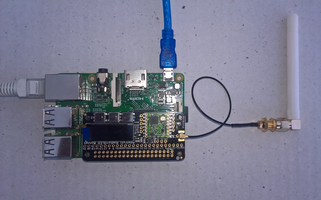
This application builds on Windows 10 IoT Core Cognitive Services Vision API client. It uses my Lego brick classifier model and a new m&m object detection model.
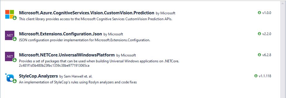
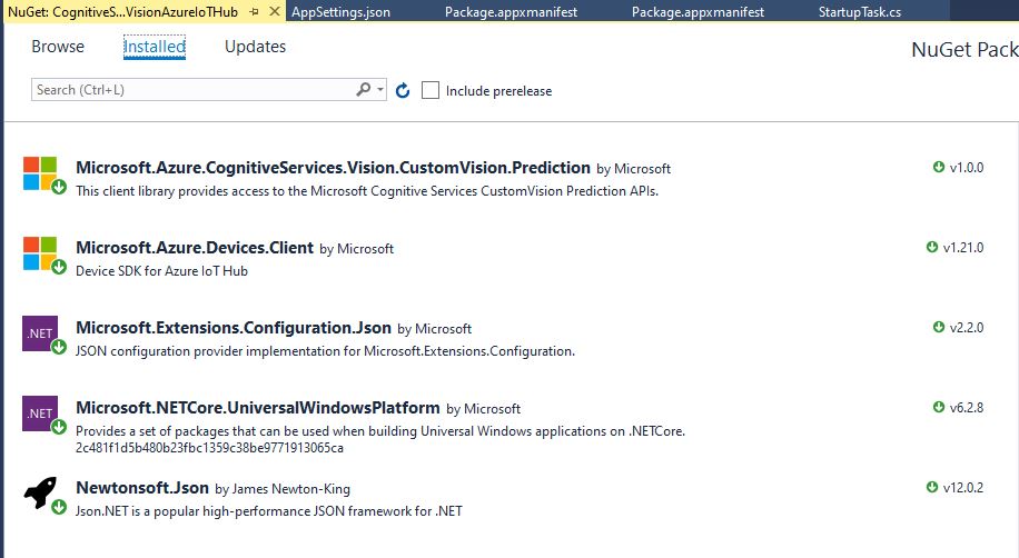
I created a new Visual Studio 2017 Windows IoT Core project and copied across the Windows 10 IoT Core Cognitive Services Custom Vision API code, (changing the namespace and manifest details) and added the Azure Devices Client NuGet package.
In the start up code I added code to initialise the Azure IoT Hub client, retrieve the device twin settings, and update the device twin properties.
try
{
	this.azureIoTHubClient = DeviceClient.CreateFromConnectionString(this.azureIoTHubConnectionString, this.transportType);
}
catch (Exception ex)
{
	this.logging.LogMessage("AzureIOT Hub DeviceClient.CreateFromConnectionString failed " + ex.Message, LoggingLevel.Error);
	return;
}

try
{
	TwinCollection reportedProperties = new TwinCollection();

	// This is from the OS
	reportedProperties["Timezone"] = TimeZoneSettings.CurrentTimeZoneDisplayName;
	reportedProperties["OSVersion"] = Environment.OSVersion.VersionString;
	reportedProperties["MachineName"] = Environment.MachineName;

	reportedProperties["ApplicationDisplayName"] = package.DisplayName;
	reportedProperties["ApplicationName"] = packageId.Name;
	reportedProperties["ApplicationVersion"] = string.Format($"{version.Major}.{version.Minor}.{version.Build}.{version.Revision}");

	// Unique identifier from the hardware
	SystemIdentificationInfo systemIdentificationInfo = SystemIdentification.GetSystemIdForPublisher();
	using (DataReader reader = DataReader.FromBuffer(systemIdentificationInfo.Id))
	{
		byte[] bytes = new byte[systemIdentificationInfo.Id.Length];
		reader.ReadBytes(bytes);
		reportedProperties["SystemId"] = BitConverter.ToString(bytes);
	}
	this.azureIoTHubClient.UpdateReportedPropertiesAsync(reportedProperties).Wait();
}
catch (Exception ex)
{
	this.logging.LogMessage("Azure IoT Hub client UpdateReportedPropertiesAsync failed " + ex.Message, LoggingLevel.Error);
	return;
}

try
{
	LoggingFields configurationInformation = new LoggingFields();

	Twin deviceTwin = this.azureIoTHubClient.GetTwinAsync().GetAwaiter().GetResult();

	if (!deviceTwin.Properties.Desired.Contains("ImageUpdateDue") || !TimeSpan.TryParse(deviceTwin.Properties.Desired["ImageUpdateDue"].value.ToString(), out imageUpdateDue))
	{
		this.logging.LogMessage("DeviceTwin.Properties ImageUpdateDue setting missing or invalid format", LoggingLevel.Warning);
		return;
	}
	configurationInformation.AddTimeSpan("ImageUpdateDue", imageUpdateDue);

	if (!deviceTwin.Properties.Desired.Contains("ImageUpdatePeriod") || !TimeSpan.TryParse(deviceTwin.Properties.Desired["ImageUpdatePeriod"].value.ToString(), out imageUpdatePeriod))
	{
		this.logging.LogMessage("DeviceTwin.Properties ImageUpdatePeriod setting missing or invalid format", LoggingLevel.Warning);
		return;
	}
…
	if (!deviceTwin.Properties.Desired.Contains("DebounceTimeout") || !TimeSpan.TryParse(deviceTwin.Properties.Desired["DebounceTimeout"].value.ToString(), out debounceTimeout))
	{
		this.logging.LogMessage("DeviceTwin.Properties DebounceTimeout setting missing or invalid format", LoggingLevel.Warning);
		return;
	}
				configurationInformation.AddTimeSpan("DebounceTimeout", debounceTimeout);

	this.logging.LogEvent("Configuration settings", configurationInformation);
}
catch (Exception ex)
{
	this.logging.LogMessage("Azure IoT Hub client GetTwinAsync failed or property missing/invalid" + ex.Message, LoggingLevel.Error);
	return;
}
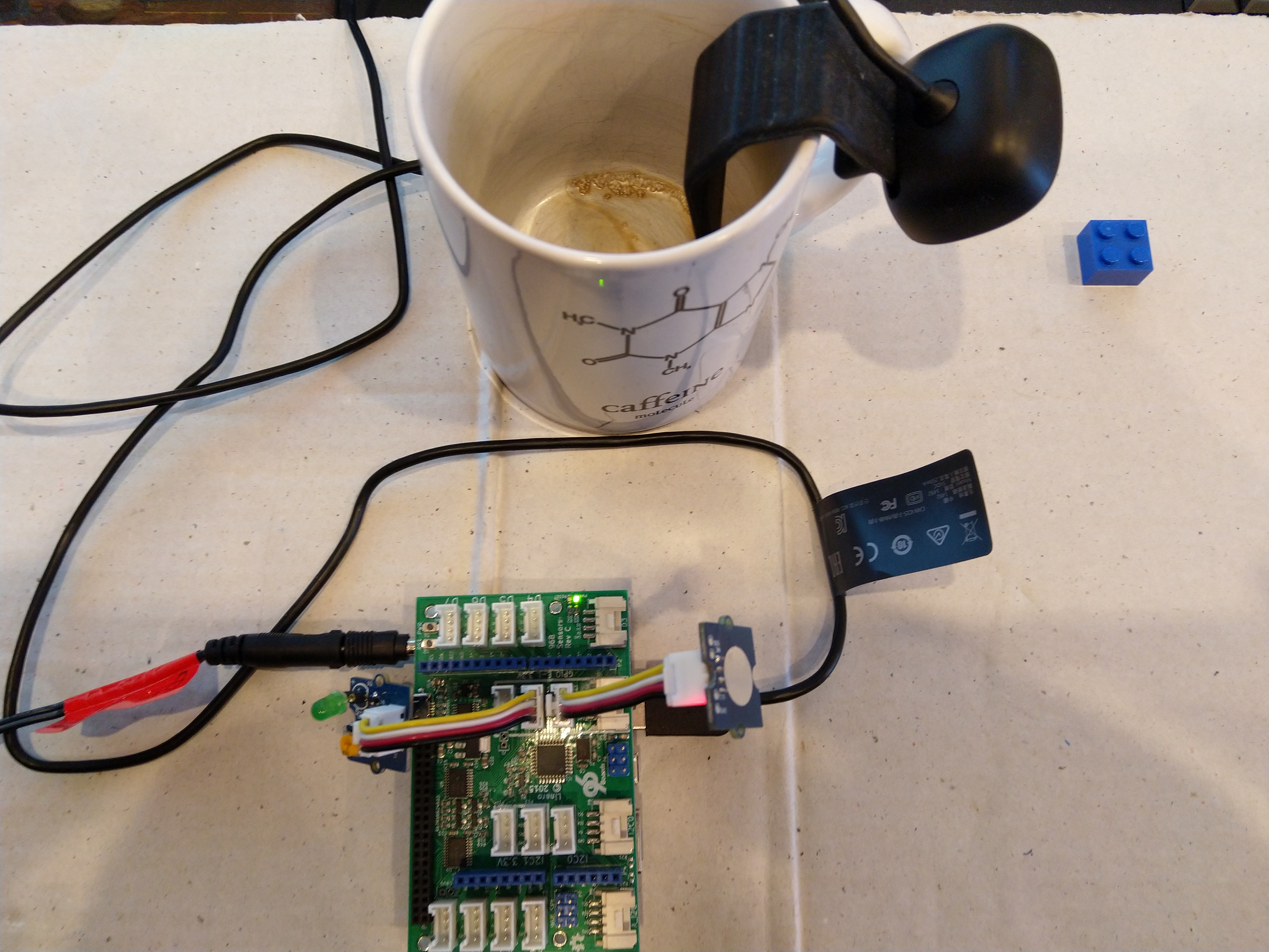
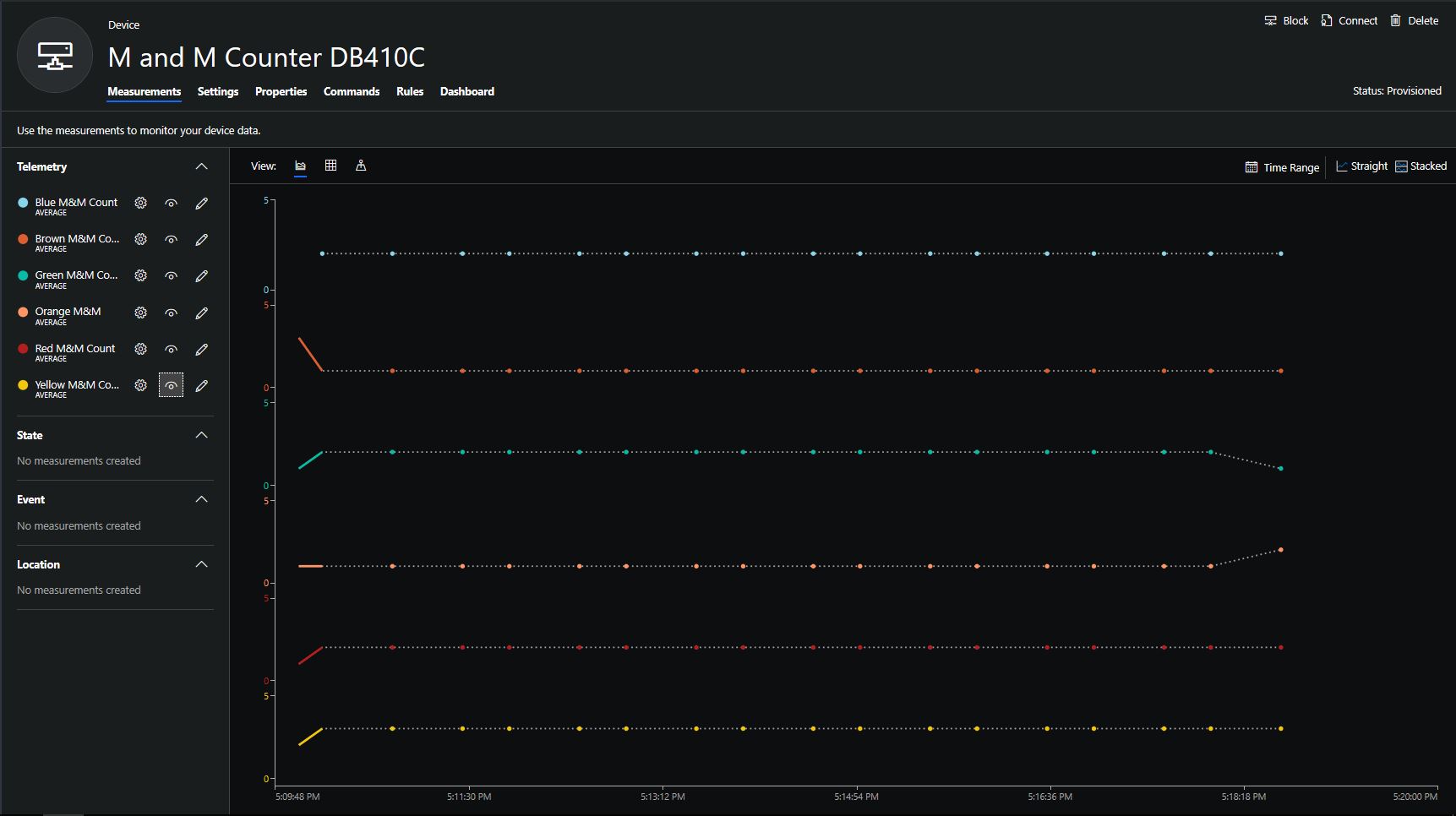
When the digital input (configured in the app.settings file) is strobed or the timer fires (configured in the device properties) an image is captured, uploaded to Azure Cognitive Services Custom Vision for processing.
The returned results are then post processed to make them Azure IoT Central friendly, and finally uploaded to an Azure IoT Hub.
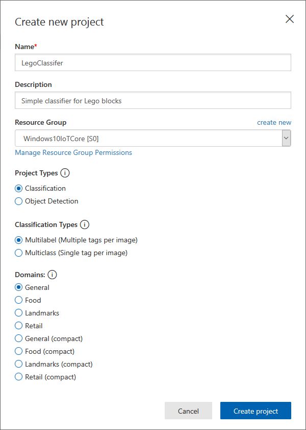
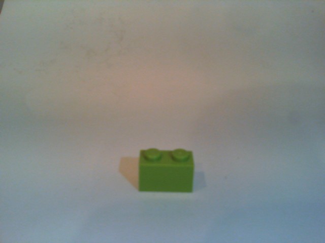
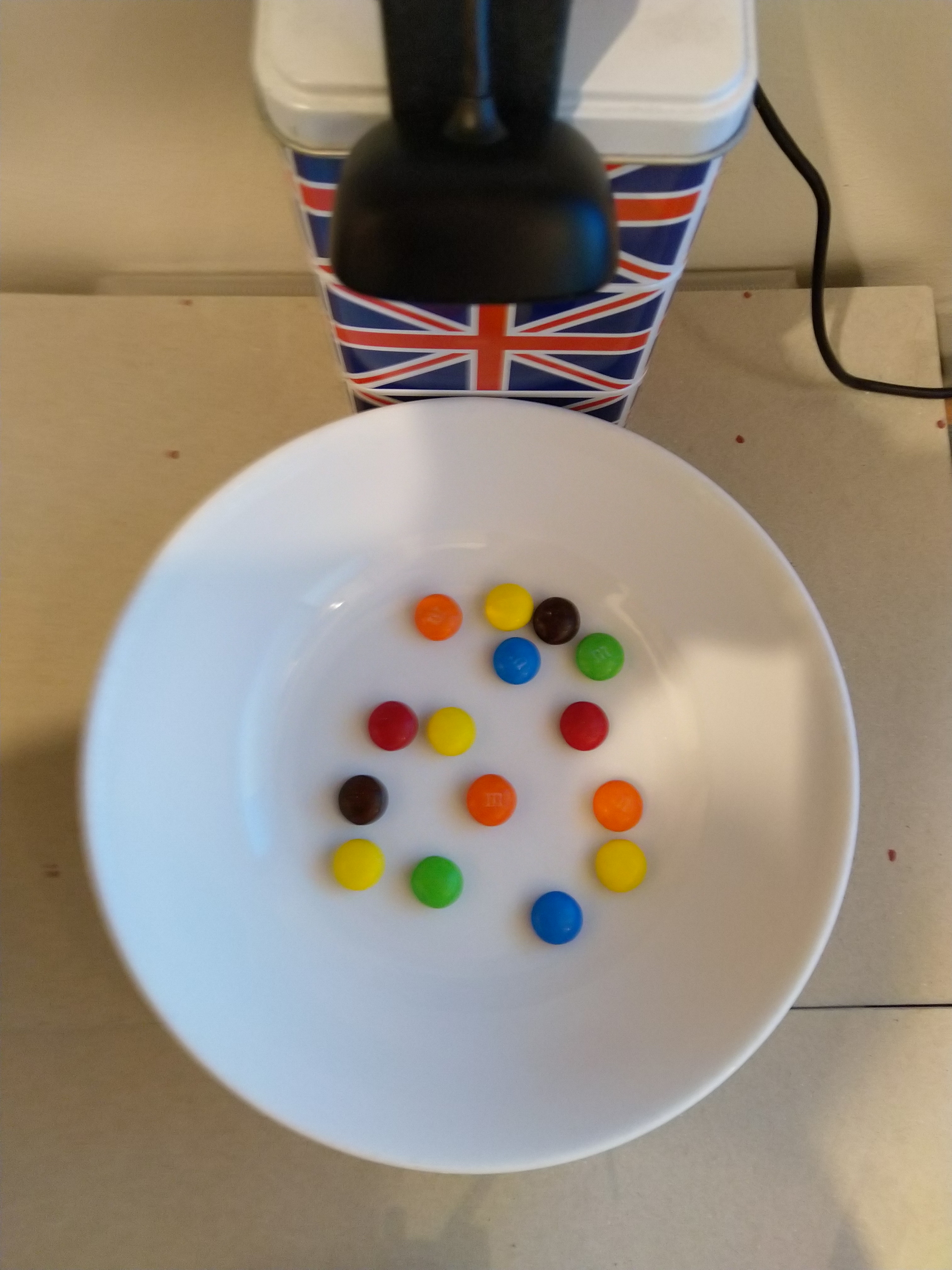
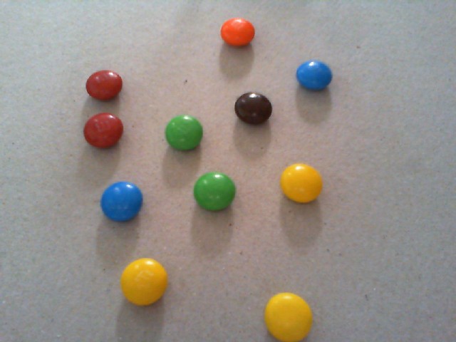
For testing I have used a simple object detection model.
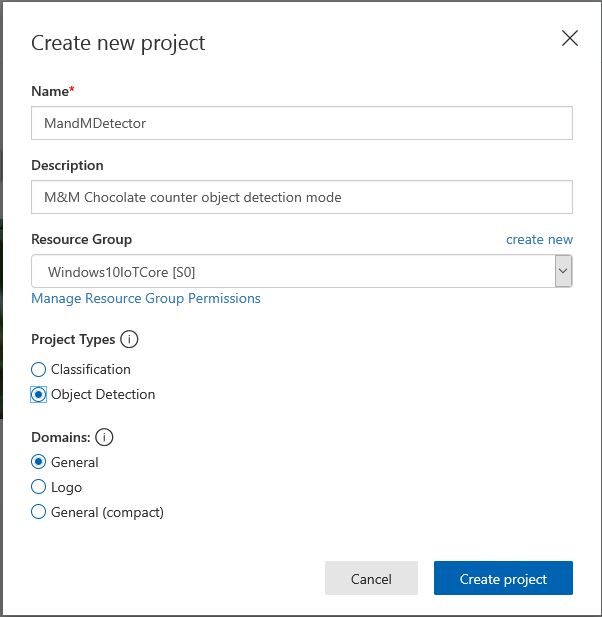
I trained the model with images of 6 different colours of m&m’s.
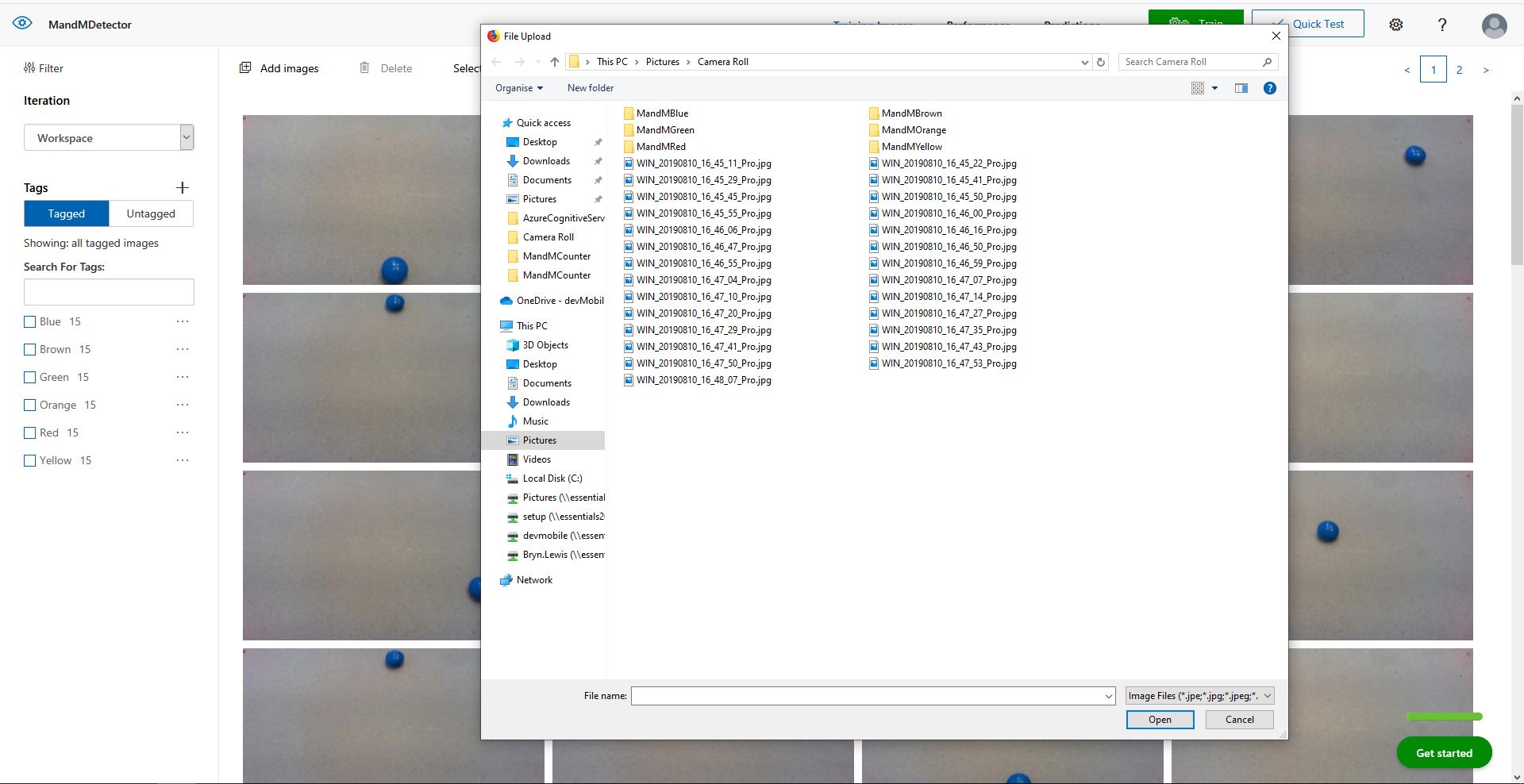
For my first dataset I tagged the location of a single m&m of each of the colour in 15 images.
I then trained the model multiple times adding additional images where the model was having trouble distiguishing colours.

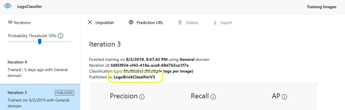
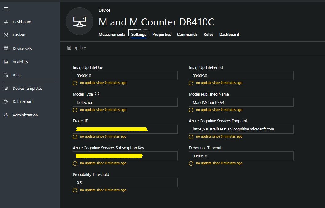
The published name comes from the training performance tab

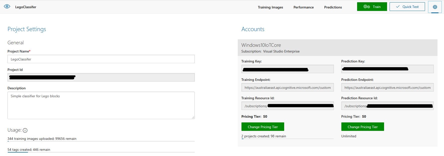
The projectID, AzureCognitiveServicesSubscriptionKey (PredictionKey) and PublishedName (From the Performance tab in project) are from the custom vision project properties.
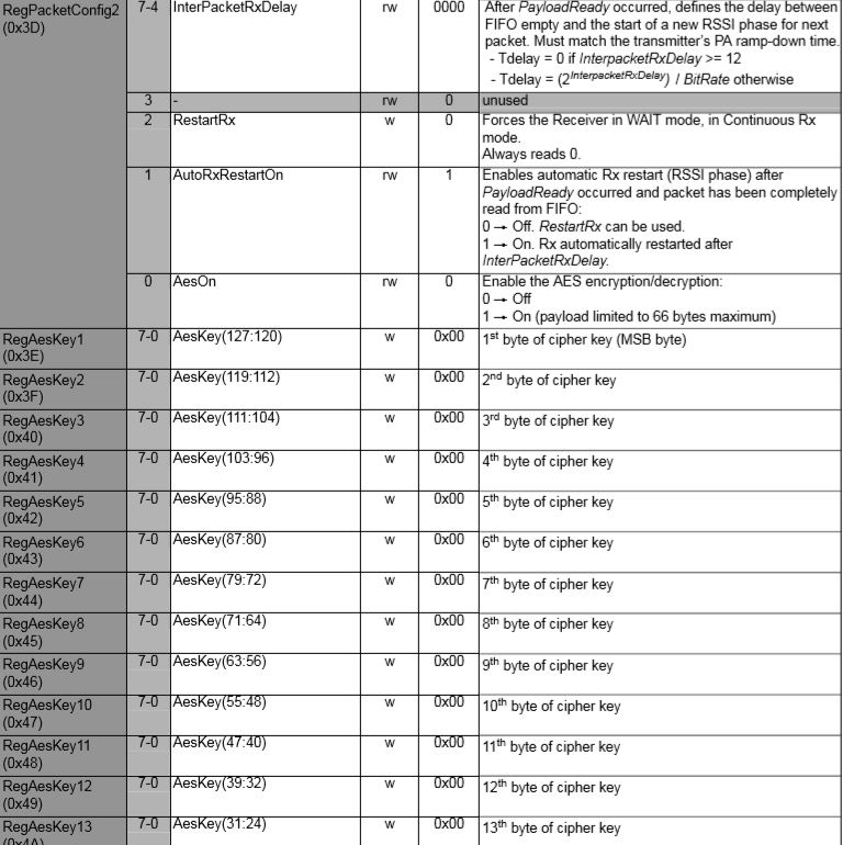
All of the Custom Vision model settings are configured in the Azure IoT Hub device properties.
The app.settings file contains only the hardware configuration settings and the Azure IoT Hub connection string.
{
  "InterruptPinNumber": 24,
  "interruptTriggerOn": "RisingEdge",
  "DisplayPinNumber": 35,
  "AzureIoTHubConnectionString": "",
  "TransportType": "Mqtt"
}
The LED connected to the display pin is illuminated while an image is being processed or briefly flashed if the insufficient time between image captures has passed.
The image data is post processed differently based on the model.
// Post process the predictions based on the type of model
switch (modelType)
{
	case ModelType.Classification:
		// Use only the tags above the specified minimum probability
		foreach (var prediction in imagePrediction.Predictions)
		{
			if (prediction.Probability >= probabilityThreshold)
			{
				// Display and log the individual tag probabilities
				Debug.WriteLine($" Tag valid:{prediction.TagName} {prediction.Probability:0.00}");
				imageInformation.AddDouble($"Tag valid:{prediction.TagName}", prediction.Probability);
					telemetryDataPoint.Add(prediction.TagName, prediction.Probability);
			}
		}
		break;

	case ModelType.Detection:
		// Group the tags to get the count, include only the predictions above the specified minimum probability
		var groupedPredictions = from prediction in imagePrediction.Predictions
										 where prediction.Probability >= probabilityThreshold
										 group prediction by new { prediction.TagName }
				into newGroup
										 select new
										 {
											 TagName = newGroup.Key.TagName,
											 Count = newGroup.Count(),
										 };

		// Display and log the agregated predictions
		foreach (var prediction in groupedPredictions)
		{
			Debug.WriteLine($" Tag valid:{prediction.TagName} {prediction.Count}");
			imageInformation.AddInt32($"Tag valid:{prediction.TagName}", prediction.Count);
			telemetryDataPoint.Add(prediction.TagName, prediction.Count);
		}
		break;
	default:
		throw new ArgumentException("ModelType Invalid");
}
For a classifier only the tags with a probability greater than or equal the specified threshold are uploaded.
For a detection model the instances of each tag are counted. Only the tags with a prediction value greater than the specified threshold are included in the count.
19-08-14 05:26:14 Timer triggered
Prediction count 33
 Tag:Blue 0.0146500813
 Tag:Blue 0.61186564
 Tag:Blue 0.0923164859
 Tag:Blue 0.7813785
 Tag:Brown 0.0100603029
 Tag:Brown 0.128318727
 Tag:Brown 0.0135991769
 Tag:Brown 0.687322736
 Tag:Brown 0.846672833
 Tag:Brown 0.1826635
 Tag:Brown 0.0183384717
 Tag:Green 0.0200069249
 Tag:Green 0.367765248
 Tag:Green 0.011428359
 Tag:Orange 0.678825438
 Tag:Orange 0.03718319
 Tag:Orange 0.8643157
 Tag:Orange 0.0296728313
 Tag:Red 0.02141669
 Tag:Red 0.7183208
 Tag:Red 0.0183610674
 Tag:Red 0.0130951973
 Tag:Red 0.82097
 Tag:Red 0.0618815944
 Tag:Red 0.0130757084
 Tag:Yellow 0.04150853
 Tag:Yellow 0.0106579047
 Tag:Yellow 0.0210028365
 Tag:Yellow 0.03392527
 Tag:Yellow 0.129197285
 Tag:Yellow 0.8089519
 Tag:Yellow 0.03723789
 Tag:Yellow 0.74729687
 Tag valid:Blue 2
 Tag valid:Brown 2
 Tag valid:Orange 2
 Tag valid:Red 2
 Tag valid:Yellow 2
 05:26:17 AzureIoTHubClient SendEventAsync start
 05:26:18 AzureIoTHubClient SendEventAsync finish
The debugging output of the application includes the different categories identified in the captured image.
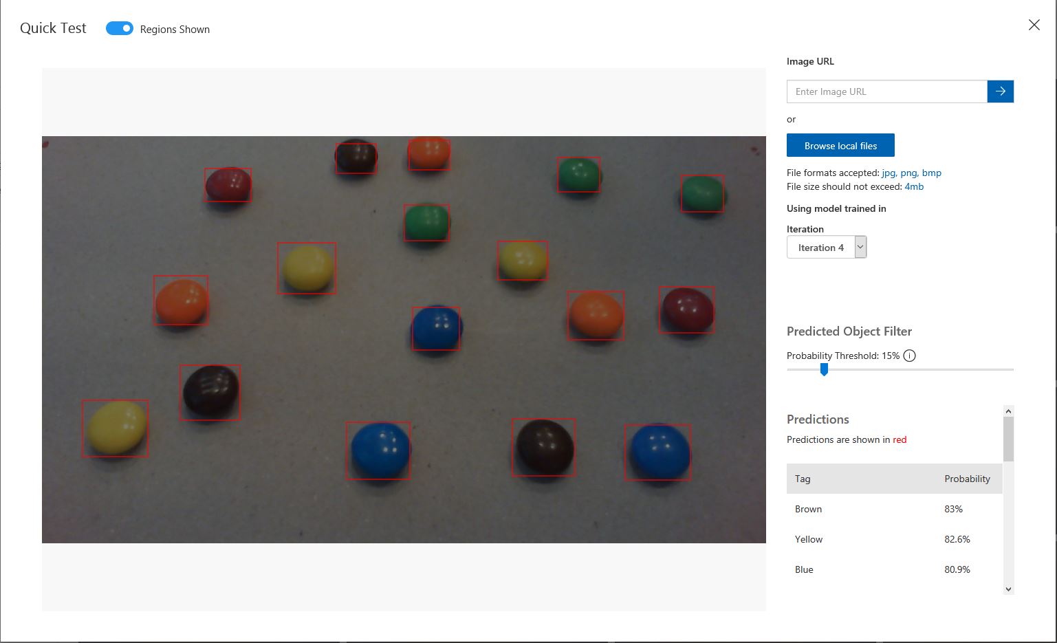
I found my small model was pretty good at detection of individual m&m as long as the ambient lighting was consistent, and the background fairly plain.
Every so often the camera contrast setting went bad and could only be restored by restarting the device which needs further investigation.

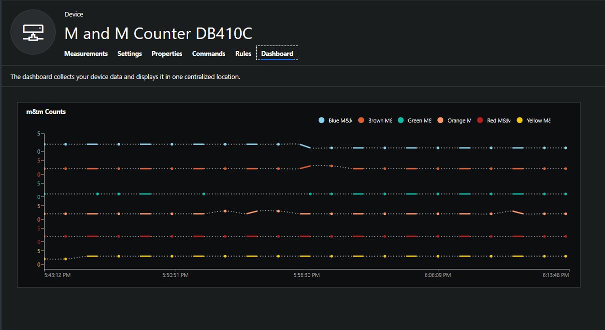
This application could be the basis for projects which need to run an Azure Cognitive Services model to count or classify then upload the results to an Azure IoT Hub or Azure IoT Central for presentation.
With a suitable model this application could be used to count the number of people in a room, which could be displayed along with the ambient temperature, humidity, CO2, and noise levels in Azure IoT Central.
The code for this application is available In on GitHub.