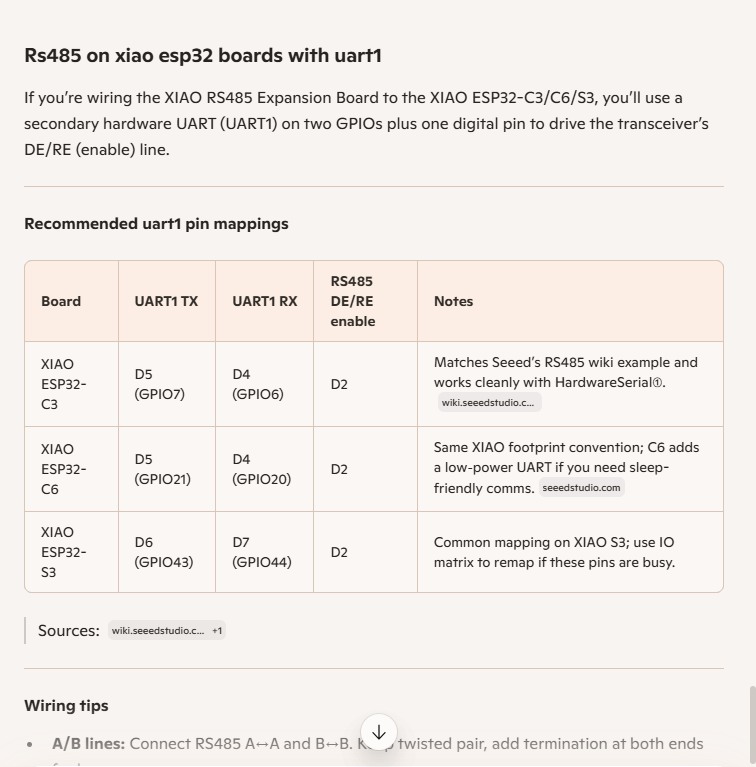
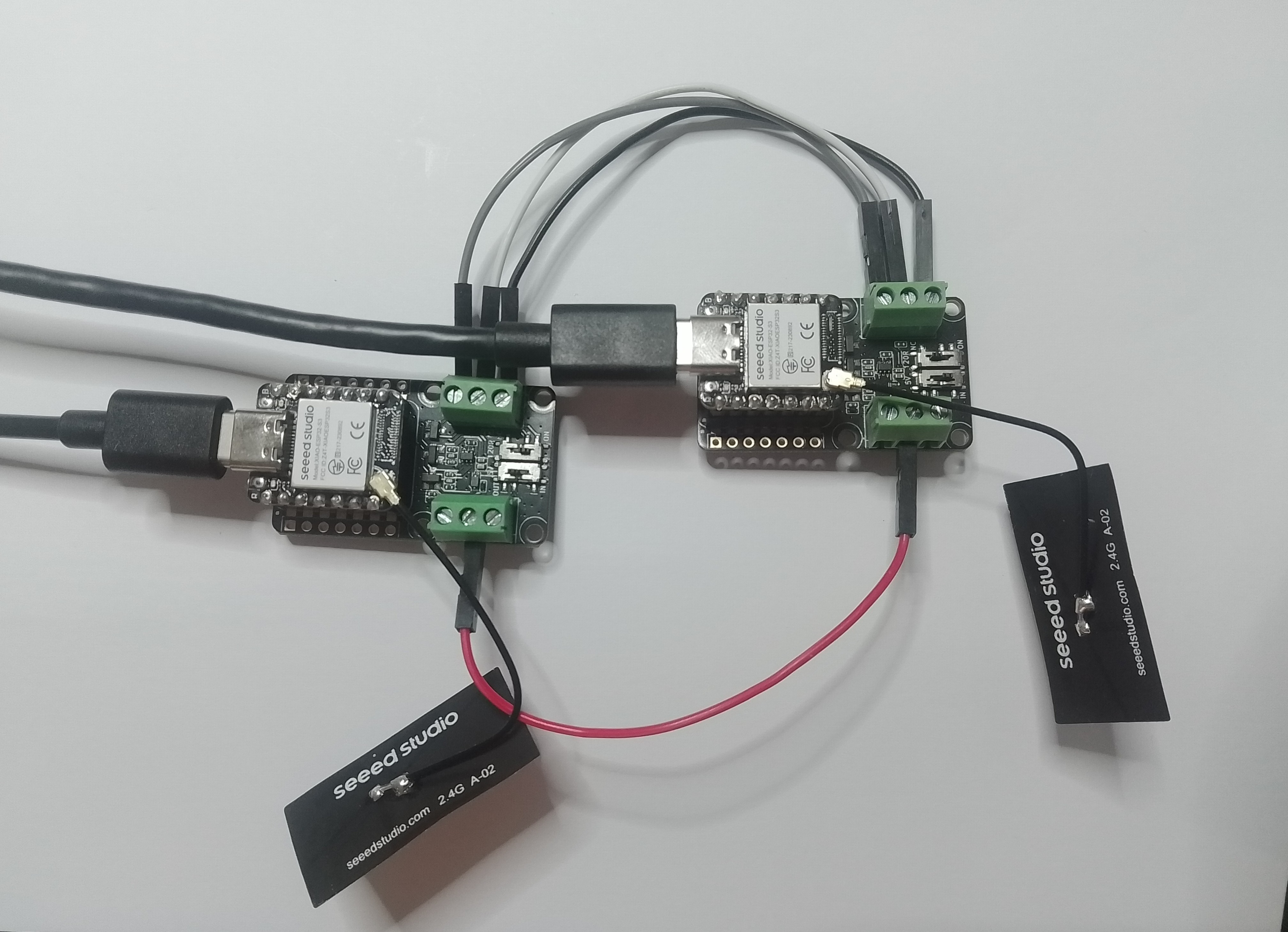
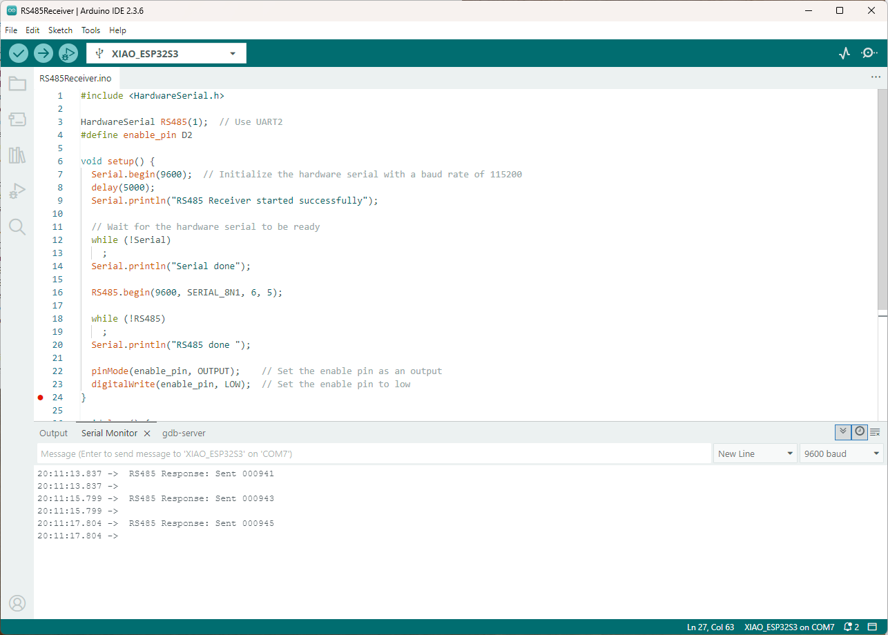
As part of a project to read values from a MODBUS RS-485 sensor using a RS-485 Breakout Board for Seeed Studio XIAO and a Seeed Studio XIAO ESP32-S3 I built a .NET nanoFramework version of the Arduino test harness described in this wiki post.
This took a bit longer than I expected mainly because running two instances of Visual Studio 2026 was a problem (running Visual Studio 2022 for one device and Visual Studio 2026 for the other, though not 100% confident this was an issue) as there were some weird interactions.
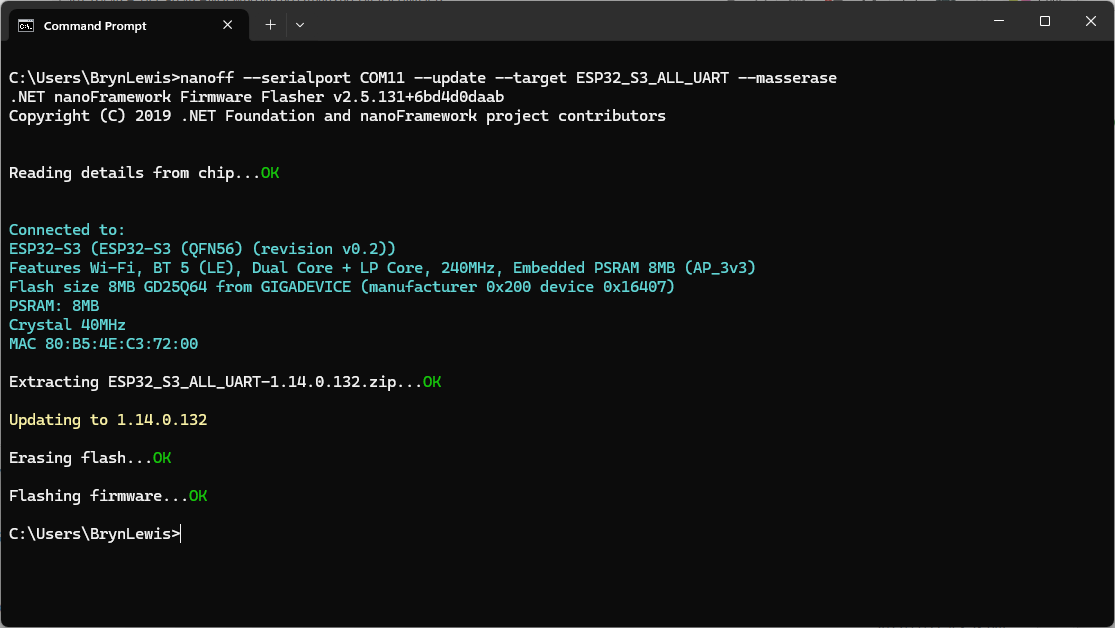
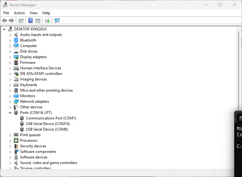
As I moved between the Arduino tooling and flashing devices with nanoff the serial port numbers would change watching the port assignments in Windows Device Manager was key.
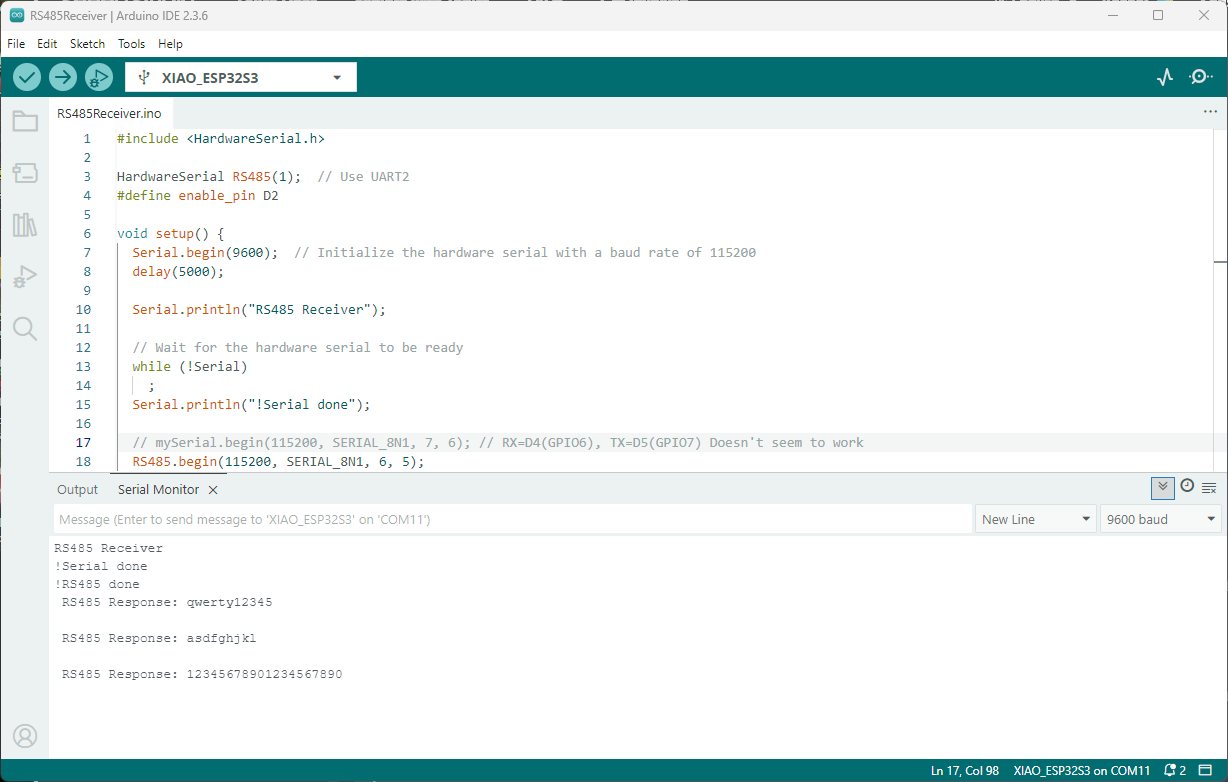
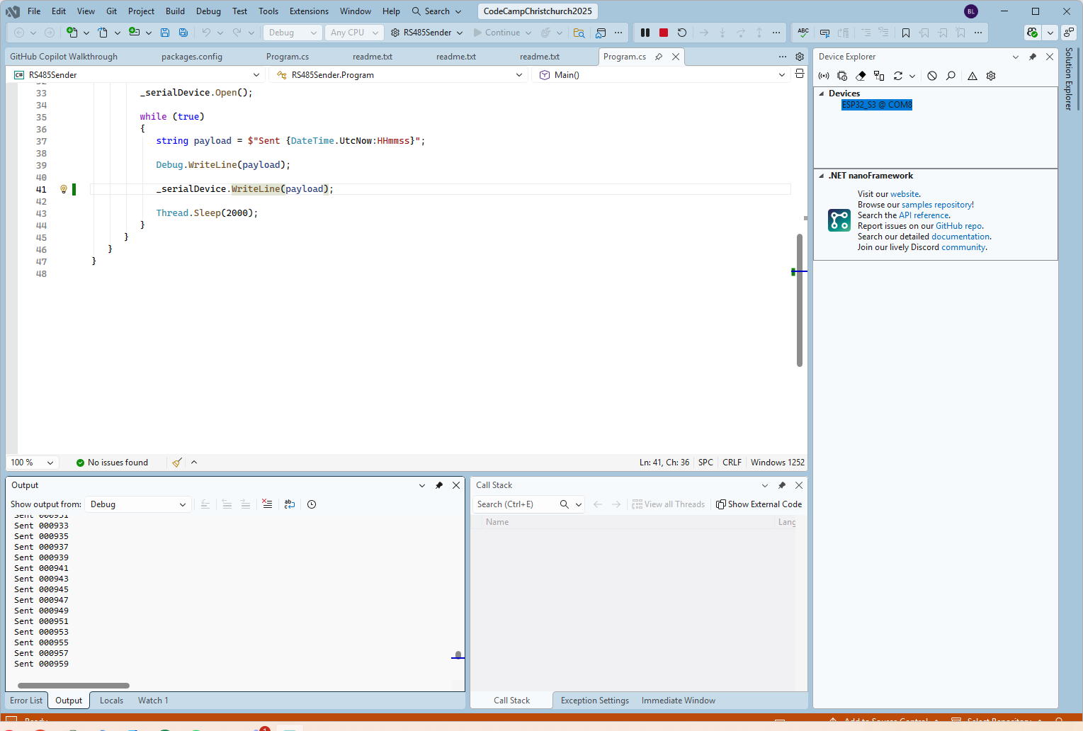
Rather than debugging both the nanoFramework RS485Sender and RS485Receiver applications simultaneously, I used the Arduino RS485Sender and RS485 Receiver application but had similar issues with the port assignments changing.

public class Program
{
   static SerialPort _serialDevice;

   public static void Main()
   {
      Configuration.SetPinFunction(Gpio.IO06, DeviceFunction.COM2_RX);
      Configuration.SetPinFunction(Gpio.IO05, DeviceFunction.COM2_TX);
      Configuration.SetPinFunction(Gpio.IO02, DeviceFunction.COM2_RTS);

      Debug.WriteLine("RS485 Sender: ");

      var ports = SerialPort.GetPortNames();

      Debug.WriteLine("Available ports: ");
      foreach (string port in ports)
      {
         Debug.WriteLine($" {port}");
      }

      _serialDevice = new SerialPort("COM2");
      _serialDevice.BaudRate = 9600;
      _serialDevice.Mode = SerialMode.RS485;

      _serialDevice.Open();

      Debug.WriteLine("Sending...");
      while (true)
      {
         string payload = $"{DateTime.UtcNow:HHmmss}";

         Debug.WriteLine($"Sent:{DateTime.UtcNow:HHmmss}");

         Debug.WriteLine(payload);

         _serialDevice.WriteLine(payload);

         Thread.Sleep(2000);
      }
   }
}
if I had built the nanoFramework RS485Sender and RS485Receiver applications first debugging the Arduino RS485Sender and RS485Receiver would been similar.
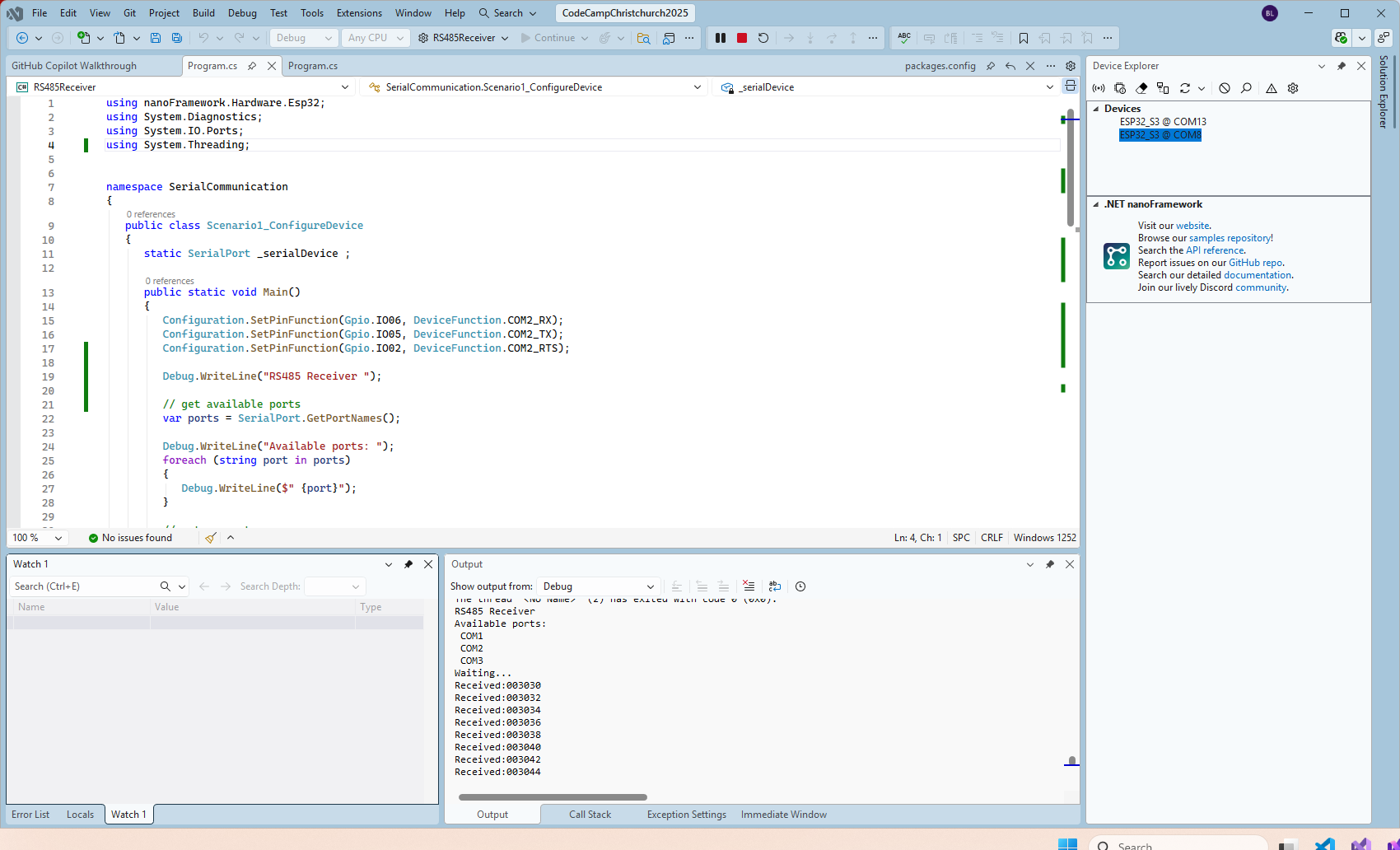
public class Program
{
   static SerialPort _serialDevice ;

   public static void Main()
   {
      Configuration.SetPinFunction(Gpio.IO06, DeviceFunction.COM2_RX);
      Configuration.SetPinFunction(Gpio.IO05, DeviceFunction.COM2_TX);
      Configuration.SetPinFunction(Gpio.IO02, DeviceFunction.COM2_RTS);

      Debug.WriteLine("RS485 Receiver ");

      // get available ports
      var ports = SerialPort.GetPortNames();

      Debug.WriteLine("Available ports: ");
      foreach (string port in ports)
      {
         Debug.WriteLine($" {port}");
      }

      // set parameters
      _serialDevice = new SerialPort("COM2");
      _serialDevice.BaudRate = 9600;
      _serialDevice.Mode = SerialMode.RS485;

      // set a watch char to be notified when it's available in the input stream
      _serialDevice.WatchChar = '\n';

      // setup an event handler that will fire when a char is received in the serial device input stream
      _serialDevice.DataReceived += SerialDevice_DataReceived;

      _serialDevice.Open();

      Debug.WriteLine("Waiting...");
      Thread.Sleep(Timeout.Infinite);
   }

   private static void SerialDevice_DataReceived(object sender, SerialDataReceivedEventArgs e)
   {
      SerialPort serialDevice = (SerialPort)sender;

      switch (e.EventType)
      {
         case SerialData.Chars:
         //break;

         case SerialData.WatchChar:
            string response = serialDevice.ReadExisting();
            Debug.Write($"Received:{response}");
            break;
         default:
            Debug.Assert(false, $"e.EventType {e.EventType} unknown");
            break;
      }
   }
}
The changing of serial port numbers while running different combinations of Arduino and nanoFramework environments concurrently combined with the sender and receiver applications having to be deployed to the right devices (also initially accidentally different baud rates) was a word of pain, and with the benefit of hindsight I should have used two computers.