.Net MicroFramework LoRa library Part7

Transmit Interrupt

Starting with the TransmitBasic sample application I modified the code so that a hardware interrupt (specified by SX1276 RegDioMapping1) was generated on TxDone (FIFO Payload Transmission completed).

The application inserts a message into the SX1276 transmit FIFO every 10 seconds with confirmation of transmission displayed shortly afterwards

//---------------------------------------------------------------------------------
// Copyright (c) August 2018, devMobile Software
//
// Licensed under the Apache License, Version 2.0 (the "License");
// you may not use this file except in compliance with the License.
// You may obtain a copy of the License at
//
//     http://www.apache.org/licenses/LICENSE-2.0
//
// Unless required by applicable law or agreed to in writing, software
// distributed under the License is distributed on an "AS IS" BASIS,
// WITHOUT WARRANTIES OR CONDITIONS OF ANY KIND, either express or implied.
// See the License for the specific language governing permissions and
// limitations under the License.
//
//---------------------------------------------------------------------------------
namespace devMobile.IoT.NetMF.Rfm9X.TransmitInterrupt
{
	using System;
	using System.Text;
	using System.Threading;
	using Microsoft.SPOT;
	using Microsoft.SPOT.Hardware;
	using SecretLabs.NETMF.Hardware.Netduino;

	public sealed class Rfm9XDevice
	{
		private const byte RegisterAddressReadMask = 0X7f;
		private const byte RegisterAddressWriteMask = 0x80;

		private SPI Rfm9XLoraModem = null;
		private OutputPort ResetGpioPin = null;
		private InterruptPort InterruptPin = null;

		public Rfm9XDevice(Cpu.Pin chipSelect, Cpu.Pin resetPin, Cpu.Pin interruptPin)
		{
			// Factory reset pin configuration
			ResetGpioPin = new OutputPort(Pins.GPIO_PIN_D9, true);
			ResetGpioPin.Write(false);
			Thread.Sleep(10);
			ResetGpioPin.Write(true);
			Thread.Sleep(10);

			this.Rfm9XLoraModem = new SPI(new SPI.Configuration(chipSelect, false, 0, 0, false, false, 2000, SPI.SPI_module.SPI1));

			InterruptPin = new InterruptPort(interruptPin, false, Port.ResistorMode.Disabled, Port.InterruptMode.InterruptEdgeHigh);

			InterruptPin.OnInterrupt += InterruptPin_OnInterrupt;

			Thread.Sleep(100);
		}

		public Byte RegisterReadByte(byte registerAddress)
		{
			byte[] writeBuffer = new byte[] { registerAddress };
			byte[] readBuffer = new byte[1];
			Debug.Assert(Rfm9XLoraModem != null);

			Rfm9XLoraModem.WriteRead(writeBuffer, readBuffer, 1);

			return readBuffer[0];
		}

		public ushort RegisterReadWord(byte address)
		{
			byte[] writeBuffer = new byte[] { address &= RegisterAddressReadMask };
			byte[] readBuffer = new byte[2];
			Debug.Assert(Rfm9XLoraModem != null);

			readBuffer[0] = RegisterReadByte(address);
			readBuffer[1] = RegisterReadByte(address += 1);

			return (ushort)(readBuffer[1] + (readBuffer[0] << 8));
		}

		public byte[] RegisterRead(byte address, int length)
		{
			byte[] writeBuffer = new byte[] { address &= RegisterAddressReadMask };
			byte[] readBuffer = new byte[length];
			Debug.Assert(Rfm9XLoraModem != null);

			for (byte index = 0; index  4];

			// Mask off the upper 4 bits to get the rest of it.
			hexString += hexChars[singlebyte & 0x0F];

			return hexString;
		}

		private static string WordToHexString(ushort singleword)
		{
			string hexString = string.Empty;

			byte[] bytes = BitConverter.GetBytes(singleword);

			hexString += ByteToHexString(bytes[1]);

			hexString += ByteToHexString(bytes[0]);

			return hexString;
		}

		void InterruptPin_OnInterrupt(uint data1, uint data2, DateTime time)
		{
			byte IrqFlags = this.RegisterReadByte(0x12); // RegIrqFlags
			Debug.Print("RegIrqFlags " + ByteToHexString(IrqFlags));

			if ((IrqFlags & 0x08) == 0x08)  // TxDone
			{
				Debug.Print("Transmit-Done");
			}

			this.RegisterWriteByte(0x12, 0xff);// RegIrqFlags
		}

		public class Program
		{
			public static void Main()
			{
				Rfm9XDevice rfm9XDevice = new Rfm9XDevice(Pins.GPIO_PIN_D10, Pins.GPIO_PIN_D9, Pins.GPIO_PIN_D2);
				byte MessageCount = byte.MinValue;

				while (true)
				{
					// Put device into LoRa + Sleep mode
					rfm9XDevice.RegisterWriteByte(0x01, 0x80); // RegOpMode 

					// Set the frequency to 915MHz
					byte[] frequencyWriteBytes = { 0xE4, 0xC0, 0x00 }; // RegFrMsb, RegFrMid, RegFrLsb
					rfm9XDevice.RegisterWrite(0x06, frequencyWriteBytes);

					// More power - PA_BOOST
					rfm9XDevice.RegisterWriteByte(0x09, 0x80); // RegPaConfig

					// Interrupt on TxDone
					rfm9XDevice.RegisterWriteByte(0x40, 0x40); // RegDioMapping1 0b00000000 DI0 TxDone

					while (true)
					{
						rfm9XDevice.RegisterWriteByte(0x0E, 0x0); // RegFifoTxBaseAddress 

						// Set the Register Fifo address pointer
						rfm9XDevice.RegisterWriteByte(0x0D, 0x0); // RegFifoAddrPtr 

						string messageText = "Hello NetMF LoRa! ";
						if (MessageCount != 0)
						{
							messageText += "-" + MessageCount.ToString();
						}
						else
						{
							messageText += MessageCount.ToString();
						}
						MessageCount += 1;

						// load the message into the fifo
						byte[] messageBytes = UTF8Encoding.UTF8.GetBytes(messageText);
						foreach (byte b in messageBytes)
						{
							rfm9XDevice.RegisterWriteByte(0x0, b); // RegFifo
						}

						// Set the length of the message in the fifo
						rfm9XDevice.RegisterWriteByte(0x22, (byte)messageBytes.Length); // RegPayloadLength

						Debug.Print("Sending " + messageBytes.Length + " bytes message " + messageText);
						/// Set the mode to LoRa + Transmit
						rfm9XDevice.RegisterWriteByte(0x01, 0x83); // RegOpMode 

						Thread.Sleep(10000);
					}
				}
			}
		}

	}
}

Unlike the Windows 10 IoT core version I can configure the interrupt to only trigger on the leading edge.

InterruptPin = new InterruptPort(interruptPin, false, Port.ResistorMode.Disabled, Port.InterruptMode.InterruptEdgeHigh);

In the Debug output window of VS2K12 I could see

The thread '' (0x2) has exited with code 0 (0x0).
Sending 19 bytes message Hello NetMF LoRa! 0
RegIrqFlags 08
Transmit-Done
Sending 20 bytes message Hello NetMF LoRa! -1
RegIrqFlags 08
Transmit-Done
Sending 20 bytes message Hello NetMF LoRa! -2
RegIrqFlags 08
Transmit-Done

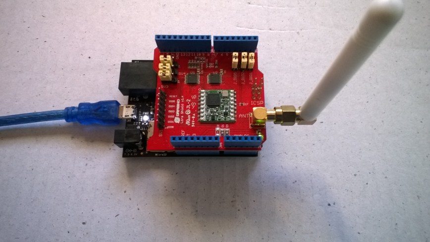
On my Arduino device the message arrived

LoRa Receiver Callback
Received packet 'Hello NetMF LoRa! 0' with RSSI -29
Received packet 'Hello NetMF LoRa! -1' with RSSI -29
Received packet 'Hello NetMF LoRa! -2' with RSSI -29
Received packet 'Hello NetMF LoRa! -3' with RSSI -29
Received packet 'Hello NetMF LoRa! -4' with RSSI -29

Next step interrupts for processing inbound messages

.Net MicroFramework LoRa library Part6

Receive Basic

I can configure the device to send messages now I need to configure the SX1276 device to receive them. For my first attempt just simple polling for a message to arrive nothing flash.

//---------------------------------------------------------------------------------
// Copyright (c) August 2018, devMobile Software
//
// Licensed under the Apache License, Version 2.0 (the "License");
// you may not use this file except in compliance with the License.
// You may obtain a copy of the License at
//
//     http://www.apache.org/licenses/LICENSE-2.0
//
// Unless required by applicable law or agreed to in writing, software
// distributed under the License is distributed on an "AS IS" BASIS,
// WITHOUT WARRANTIES OR CONDITIONS OF ANY KIND, either express or implied.
// See the License for the specific language governing permissions and
// limitations under the License.
//
//---------------------------------------------------------------------------------
namespace devMobile.IoT.NetMF.Rfm9X.ReceiveBasic
{
   using System;
   using System.Text;
   using System.Threading;
   using Microsoft.SPOT;
   using Microsoft.SPOT.Hardware;
   using SecretLabs.NETMF.Hardware.Netduino;

   public sealed class Rfm9XDevice
   {
      private const byte RegisterAddressReadMask = 0X7f;
      private const byte RegisterAddressWriteMask = 0x80;

      private SPI Rfm9XLoraModem = null;
      private OutputPort ResetGpioPin = null;

      public Rfm9XDevice(Cpu.Pin chipSelect, Cpu.Pin reset)
      {
         // Factory reset pin configuration
         ResetGpioPin = new OutputPort(Pins.GPIO_PIN_D9, true);
         ResetGpioPin.Write(false);
         Thread.Sleep(10);
         ResetGpioPin.Write(true);
         Thread.Sleep(10);

         this.Rfm9XLoraModem = new SPI(new SPI.Configuration(chipSelect, false, 0, 0, false, false, 2000, SPI.SPI_module.SPI1));

         Thread.Sleep(100);
      }

      public Byte RegisterReadByte(byte registerAddress)
      {
         byte[] writeBuffer = new byte[] { registerAddress };
         byte[] readBuffer = new byte[1];
         Debug.Assert(Rfm9XLoraModem != null);

         Rfm9XLoraModem.WriteRead(writeBuffer, readBuffer, 1);

         return readBuffer[0];
      }

      public ushort RegisterReadWord(byte address)
      {
         byte[] writeBuffer = new byte[] { address &= RegisterAddressReadMask };
         byte[] readBuffer = new byte[2];
         Debug.Assert(Rfm9XLoraModem != null);

         readBuffer[0] = RegisterReadByte(address);
         readBuffer[1] = RegisterReadByte(address += 1);

         return (ushort)(readBuffer[1] + (readBuffer[0] << 8));
      }

      public byte[] RegisterRead(byte address, int length)
      {
         byte[] writeBuffer = new byte[] { address &= RegisterAddressReadMask };
         byte[] readBuffer = new byte[length];
         Debug.Assert(Rfm9XLoraModem != null);

         for (byte index = 0; index < length; index++)
         {
            readBuffer[index] = RegisterReadByte(address += 1);
         }

         return readBuffer;
      }

      public void RegisterWriteByte(byte address, byte value)
      {
         byte[] writeBuffer = new byte[] { address |= RegisterAddressWriteMask, value };
         Debug.Assert(Rfm9XLoraModem != null);

         Rfm9XLoraModem.Write(writeBuffer);
      }

      public void RegisterWriteWord(byte address, ushort value)
      {
         byte[] valueBytes = BitConverter.GetBytes(value);
         byte[] writeBuffer = new byte[] { address |= RegisterAddressWriteMask, valueBytes[0], valueBytes[1] };
         Debug.Assert(Rfm9XLoraModem != null);

         Rfm9XLoraModem.Write(writeBuffer);
      }

      public void RegisterWrite(byte address, byte[] bytes)
      {
         byte[] writeBuffer = new byte[1 + bytes.Length];
         Debug.Assert(Rfm9XLoraModem != null);

         Array.Copy(bytes, 0, writeBuffer, 1, bytes.Length);
         writeBuffer[0] = address |= RegisterAddressWriteMask;

         Rfm9XLoraModem.Write(writeBuffer);
      }

      public void RegisterDump()
      {
         Debug.Print("---Registers 0x00 thru 0x42---");
         for (byte registerIndex = 0; registerIndex  4];

         // Mask off the upper 4 bits to get the rest of it.
         hexString += hexChars[singlebyte & 0x0F];

         return hexString;
      }

      private static string WordToHexString(ushort singleword)
      {
         string hexString = string.Empty;

         byte[] bytes = BitConverter.GetBytes(singleword);

         hexString += ByteToHexString(bytes[1]);

         hexString += ByteToHexString(bytes[0]);

         return hexString;
      }
   }
}

In the debug window I could see messages from one of my arduino devices

The thread '' (0x2) has exited with code 0 (0x0).
Receive-Wait
.
.
.
.
.
.
.

.
.
.
.

Receive-Message
Received 15 byte message HeLoRa World! 0
Receive-Done
Receive-Wait
.
.
.
.
.
.
.
.
.
.
.

Receive-Message
Received 15 byte message HeLoRa World! 2
Receive-Done
Receive-Wait
.
.

Next steps handling inbound & outbound messages with interrupts, then integrating all the samples into a useful functional V1 library.

.Net MicroFramework LoRa library Part5

Transmit Basic

Finally at the point where I can send a message to one of my Windows 10 IoT Core devices. Not going to use interrupts, just putting the bytes to send into the SX1276 Fifo and looping until they are sent.

//---------------------------------------------------------------------------------
// Copyright (c) August 2018, devMobile Software
//
// Licensed under the Apache License, Version 2.0 (the "License");
// you may not use this file except in compliance with the License.
// You may obtain a copy of the License at
//
//     http://www.apache.org/licenses/LICENSE-2.0
//
// Unless required by applicable law or agreed to in writing, software
// distributed under the License is distributed on an "AS IS" BASIS,
// WITHOUT WARRANTIES OR CONDITIONS OF ANY KIND, either express or implied.
// See the License for the specific language governing permissions and
// limitations under the License.
//
//---------------------------------------------------------------------------------
namespace devMobile.IoT.NetMF.Rfm9X.TransmitBasic
{
   using System;
   using System.Text;
   using System.Threading;
   using Microsoft.SPOT;
   using Microsoft.SPOT.Hardware;
   using SecretLabs.NETMF.Hardware.Netduino;

   public sealed class Rfm9XDevice
   {
      private const byte RegisterAddressReadMask = 0X7f;
      private const byte RegisterAddressWriteMask = 0x80;

      private SPI Rfm9XLoraModem = null;
      private OutputPort ResetGpioPin = null;

      public Rfm9XDevice(Cpu.Pin chipSelect, Cpu.Pin reset)
      {
         // Factory reset pin configuration
         ResetGpioPin = new OutputPort(Pins.GPIO_PIN_D9, true);
         ResetGpioPin.Write(false);
         Thread.Sleep(10);
         ResetGpioPin.Write(true);
         Thread.Sleep(10);

         //this.Rfm9XLoraModem = new SPI(new SPI.Configuration(chipSelect, false, 0, 0, false, true, 2000, SPI.SPI_module.SPI1));
         this.Rfm9XLoraModem = new SPI(new SPI.Configuration(chipSelect, false, 0, 0, false, false, 2000, SPI.SPI_module.SPI1));

         Thread.Sleep(100);
      }

      public Byte RegisterReadByte(byte registerAddress)
      {
         byte[] writeBuffer = new byte[] { registerAddress };
         byte[] readBuffer = new byte[1];
         Debug.Assert(Rfm9XLoraModem != null);

         //Rfm9XLoraModem.WriteRead(writeBuffer, readBuffer, 1);
         Rfm9XLoraModem.WriteRead(writeBuffer, readBuffer, 1);

         return readBuffer[0];
      }

      public ushort RegisterReadWord(byte address)
      {
         byte[] writeBuffer = new byte[] { address &amp;= RegisterAddressReadMask };
         byte[] readBuffer = new byte[2];
         Debug.Assert(Rfm9XLoraModem != null);

         //Rfm9XLoraModem.WriteRead(readBuffer, writeBuffer, 1 ); // Check this

         readBuffer[0] = RegisterReadByte(address);
         readBuffer[1] = RegisterReadByte(address += 1);

         return (ushort)(readBuffer[1] + (readBuffer[0] &lt;<span id="mce_SELREST_start" style="overflow:hidden;line-height:0;"></span>&lt; 8));
      }

      public byte[] RegisterRead(byte address, int length)
      {
         byte[] writeBuffer = new byte[] { address &amp;= RegisterAddressReadMask };
         byte[] readBuffer = new byte[length];
         Debug.Assert(Rfm9XLoraModem != null);

         //Rfm9XLoraModem.WriteRead(readBuffer, writeBuffer, 1); // Check this

         for (byte index = 0; index  4];

         // Mask off the upper 4 bits to get the rest of it.
         hexString += hexChars[singlebyte &amp; 0x0F];

         return hexString;
      }

      private static string WordToHexString(ushort singleword)
      {
         string hexString = string.Empty;

         byte[] bytes = BitConverter.GetBytes(singleword);

         hexString += ByteToHexString(bytes[1]);

         hexString += ByteToHexString(bytes[0]);

         return hexString;
      }

   }
}

The debugging output of the device shows the message being transmitted

The thread '' (0x2) has exited with code 0 (0x0).
Sending 17 bytes message Hello NetMF LoRa!
Send-wait
.
.
.
.
.
Send-Done
Sending 17 bytes message Hello NetMF LoRa!
Send-wait
.
.
.
.
.
Send-Done

On my Windows 10 IoT core device I could see the messages arriving

RegIrqFlags 01010000
Receive-Message
Received 17 byte message Hello NetMF LoRa!
The thread 0x6b4 has exited with code 0 (0x0).
Sending 22 bytes message W10 IoT Core LoRa! 252
RegIrqFlags 00001000
Transmit-Done
RegIrqFlags 01010000
Receive-Message
Received 17 byte message Hello NetMF LoRa!
The program '[2932] backgroundTaskHost.exe' has exited with code -1 (0xffffffff).

All default settings for not a lot of range etc. but it works

.Net MicroFramework LoRa library Part4

Register Read and Write

For configuration and operation I extended the RegisterManager class with methods for reading/writing bytes, words and byte arrays.

//---------------------------------------------------------------------------------
// Copyright (c) August 2018, devMobile Software
//
// Licensed under the Apache License, Version 2.0 (the "License");
// you may not use this file except in compliance with the License.
// You may obtain a copy of the License at
//
//     http://www.apache.org/licenses/LICENSE-2.0
//
// Unless required by applicable law or agreed to in writing, software
// distributed under the License is distributed on an "AS IS" BASIS,
// WITHOUT WARRANTIES OR CONDITIONS OF ANY KIND, either express or implied.
// See the License for the specific language governing permissions and
// limitations under the License.
//
//---------------------------------------------------------------------------------
namespace devMobile.IoT.NetMF.Rfm9X.RegisterReadandWrite
{
   using System;
   using System.Threading;
   using Microsoft.SPOT;
   using Microsoft.SPOT.Hardware;
   using SecretLabs.NETMF.Hardware.Netduino;

   public sealed class Rfm9XDevice
   {
      private const byte RegisterAddressReadMask = 0X7f;
      private const byte RegisterAddressWriteMask = 0x80;

      private SPI Rfm9XLoraModem = null;
      private OutputPort ResetGpioPin = null;

      public Rfm9XDevice(Cpu.Pin chipSelect, Cpu.Pin reset)
      {
         // Factory reset pin configuration
         ResetGpioPin = new OutputPort(Pins.GPIO_PIN_D9, true);
         ResetGpioPin.Write(false);
         Thread.Sleep(10);
         ResetGpioPin.Write(true);
         Thread.Sleep(10);

         //this.Rfm9XLoraModem = new SPI(new SPI.Configuration(chipSelect, false, 0, 0, false, true, 2000, SPI.SPI_module.SPI1));
         this.Rfm9XLoraModem = new SPI(new SPI.Configuration(chipSelect, false, 0, 0, false, false, 2000, SPI.SPI_module.SPI1));

         Thread.Sleep(100);
      }

      public Byte RegisterReadByte(byte registerAddress)
      {
         byte[] writeBuffer = new byte[] { registerAddress };
         byte[] readBuffer = new byte[1];
         Debug.Assert(Rfm9XLoraModem != null);

         //Rfm9XLoraModem.WriteRead(writeBuffer, readBuffer, 1);
         Rfm9XLoraModem.WriteRead(writeBuffer, readBuffer, 1 );

         return readBuffer[0];
      }

      public ushort RegisterReadWord(byte address)
      {
         byte[] writeBuffer = new byte[] { address &= RegisterAddressReadMask };
         byte[] readBuffer = new byte[2];
         Debug.Assert(Rfm9XLoraModem != null);

         //Rfm9XLoraModem.WriteRead(readBuffer, writeBuffer, 4 ); // Check this

         readBuffer[0] = RegisterReadByte( address ) ;
         readBuffer[1] = RegisterReadByte(address+=1);

         return (ushort)(readBuffer[1] + (readBuffer[0] << 8));
      }

      public byte[] RegisterRead(byte address, int length)
      {
         byte[] writeBuffer = new byte[] { address &= RegisterAddressReadMask };
         byte[] readBuffer = new byte[length];
         Debug.Assert(Rfm9XLoraModem != null);

         //Rfm9XLoraModem.WriteRead(readBuffer, writeBuffer, 1); // Check this

         for (byte index = 0; index  4];

         // Mask off the upper 4 bits to get the rest of it.
         hexString += hexChars[singlebyte & 0x0F];

         return hexString;
      }

      private static string WordToHexString(ushort singleword)
      {
         string hexString = string.Empty;

         byte[] bytes = BitConverter.GetBytes(singleword);

         hexString += ByteToHexString(bytes[1]);

         hexString += ByteToHexString(bytes[0]);

         return hexString;
      }

   }
}

I had to add an extra "ToHexString" method so I could display the returned byte and word values

Read RegOpMode (read byte)
RegOpMode 0x09
Set LoRa mode and sleep mode (write byte)
Read the preamble (read word)
Preamble 0x0008
Set the preamble to 0x80 (write word)
Read the centre frequency (read byte array)
Frequency Msb 0x80 Mid 0x00 Lsb 0x4F
Set the centre frequency to 916MHz (write byte array)
—Registers 0x00 thru 0x42—
Register 0x00 – Value 0XF4
Register 0x01 – Value 0X80
Register 0x02 – Value 0X1A
Register 0x03 – Value 0X0B
Register 0x04 – Value 0X00
Register 0x05 – Value 0X52
Register 0x06 – Value 0XE4
Register 0x07 – Value 0XC0
Register 0x08 – Value 0X00
Register 0x09 – Value 0X4F
Register 0x0A – Value 0X09
Register 0x0B – Value 0X2B
Register 0x0C – Value 0X20
Register 0x0D – Value 0X01
Register 0x0E – Value 0X80
Register 0x0F – Value 0X00
Register 0x10 – Value 0X00
Register 0x11 – Value 0X00
Register 0x12 – Value 0X00
Register 0x13 – Value 0X00
Register 0x14 – Value 0X00
Register 0x15 – Value 0X00
Register 0x16 – Value 0X00
Register 0x17 – Value 0X00
Register 0x18 – Value 0X10
Register 0x19 – Value 0X00
Register 0x1A – Value 0X00
Register 0x1B – Value 0X00
Register 0x1C – Value 0X00
Register 0x1D – Value 0X72
Register 0x1E – Value 0X70
Register 0x1F – Value 0X64
Register 0x20 – Value 0X80
Register 0x21 – Value 0X00
Register 0x22 – Value 0X01
Register 0x23 – Value 0XFF
Register 0x24 – Value 0X00
Register 0x25 – Value 0X00
Register 0x26 – Value 0X04
Register 0x27 – Value 0X00
Register 0x28 – Value 0X00
Register 0x29 – Value 0X00
Register 0x2A – Value 0X00
Register 0x2B – Value 0X00
Register 0x2C – Value 0X00
Register 0x2D – Value 0X50
Register 0x2E – Value 0X14
Register 0x2F – Value 0X45
Register 0x30 – Value 0X55
Register 0x31 – Value 0XC3
Register 0x32 – Value 0X05
Register 0x33 – Value 0X27
Register 0x34 – Value 0X1C
Register 0x35 – Value 0X0A
Register 0x36 – Value 0X03
Register 0x37 – Value 0X0A
Register 0x38 – Value 0X42
Register 0x39 – Value 0X12
Register 0x3A – Value 0X49
Register 0x3B – Value 0X1D
Register 0x3C – Value 0X00
Register 0x3D – Value 0XAF
Register 0x3E – Value 0X00
Register 0x3F – Value 0X00
Register 0x40 – Value 0X00
Register 0x41 – Value 0X00
Register 0x42 – Value 0X12

The register dump shows the SX1276 is in LoRa+Sleep mode and the preamble is set to 0x80 etc.

The way I read words and arrays of bytes isn’t very efficient will need to revisit when I have more time and/or access to a digital storage scope.

.Net MicroFramework LoRa library Part3

Register Scan

Next step was to scan the Semtech SX127X registers and check the values were as expected

//---------------------------------------------------------------------------------
// Copyright (c) August 2018, devMobile Software
//
// Licensed under the Apache License, Version 2.0 (the "License");
// you may not use this file except in compliance with the License.
// You may obtain a copy of the License at
//
//     http://www.apache.org/licenses/LICENSE-2.0
//
// Unless required by applicable law or agreed to in writing, software
// distributed under the License is distributed on an "AS IS" BASIS,
// WITHOUT WARRANTIES OR CONDITIONS OF ANY KIND, either express or implied.
// See the License for the specific language governing permissions and
// limitations under the License.
//
//---------------------------------------------------------------------------------
namespace devMobile.IoT.NetMF.Rfm9X.RegisterScan
{
   using System;
   using System.Threading;
   using Microsoft.SPOT;
   using Microsoft.SPOT.Hardware;
   using SecretLabs.NETMF.Hardware.Netduino;

   public sealed class Rfm9XDevice
   {
      private SPI rfm9XLoraModem = null;

      public Rfm9XDevice(Cpu.Pin chipSelect)
      {
         this.rfm9XLoraModem = new SPI(new SPI.Configuration(chipSelect, false, 0, 0, false, true, 500, SPI.SPI_module.SPI1));

         Thread.Sleep(100);
      }

      public Byte RegisterReadByte(byte registerAddress)
      {
         byte[] writeBuffer = new byte[] { registerAddress };
         byte[] readBuffer = new byte[1];
         Debug.Assert(rfm9XLoraModem != null);

         rfm9XLoraModem.WriteRead(writeBuffer, readBuffer, 1);

         return readBuffer[0];
      }
   }

   public class Program
   {
      public static void Main()
      {
         Rfm9XDevice rfm9XDevice = new Rfm9XDevice(Pins.GPIO_PIN_D10);

         while (true)
         {
            Debug.Print("---Registers 0x00 thru 0x42---");
            for (byte registerIndex = 0; registerIndex > 4];

         // Mask off the upper 4 bits to get the rest of it.
         hexString += hexChars[singlebyte & 0x0F];

         return hexString;
      }
   }
}

On start-up the device is not in LoRa mode so some weren’t set up properly.

---Registers 0x00 thru 0x42---
Register 0x00 - Value 0X00
Register 0x01 - Value 0X09
Register 0x02 - Value 0X1A
Register 0x03 - Value 0X0B
Register 0x04 - Value 0X00
Register 0x05 - Value 0X52
Register 0x06 - Value 0X6C
Register 0x07 - Value 0X80
Register 0x08 - Value 0X00
Register 0x09 - Value 0X4F
Register 0x0A - Value 0X09
Register 0x0B - Value 0X2B
Register 0x0C - Value 0X20
Register 0x0D - Value 0X08
Register 0x0E - Value 0X02
Register 0x0F - Value 0X0A
Register 0x10 - Value 0XFF
Register 0x11 - Value 0X70
Register 0x12 - Value 0X15
Register 0x13 - Value 0X0B
Register 0x14 - Value 0X28
Register 0x15 - Value 0X0C
Register 0x16 - Value 0X12
Register 0x17 - Value 0X47
Register 0x18 - Value 0X32
Register 0x19 - Value 0X3E
Register 0x1A - Value 0X00
Register 0x1B - Value 0X00
Register 0x1C - Value 0X00
Register 0x1D - Value 0X00
Register 0x1E - Value 0X00
Register 0x1F - Value 0X40
Register 0x20 - Value 0X00
Register 0x21 - Value 0X00
Register 0x22 - Value 0X00
Register 0x23 - Value 0X00
Register 0x24 - Value 0X05
Register 0x25 - Value 0X00
Register 0x26 - Value 0X03
Register 0x27 - Value 0X93
Register 0x28 - Value 0X55
Register 0x29 - Value 0X55
Register 0x2A - Value 0X55
Register 0x2B - Value 0X55
Register 0x2C - Value 0X55
Register 0x2D - Value 0X55
Register 0x2E - Value 0X55
Register 0x2F - Value 0X55
Register 0x30 - Value 0X90
Register 0x31 - Value 0X40
Register 0x32 - Value 0X40
Register 0x33 - Value 0X00
Register 0x34 - Value 0X00
Register 0x35 - Value 0X0F
Register 0x36 - Value 0X00
Register 0x37 - Value 0X00
Register 0x38 - Value 0X00
Register 0x39 - Value 0XF5
Register 0x3A - Value 0X20
Register 0x3B - Value 0X82
Register 0x3C - Value 0X00
Register 0x3D - Value 0X02
Register 0x3E - Value 0X80
Register 0x3F - Value 0X40
Register 0x40 - Value 0X00
Register 0x41 - Value 0X00
Register 0x42 - Value 0X12

Next step reading & writing registers


.Net MicroFramework LoRa library Part2

Register Read

Getting this bit too work took a bit longer than expected. The code below works but isn’t super efficient. I must be reading the SX1276 SPI timing diagram wrong or I need to read the .NetMF SPI implementation code some more.

//---------------------------------------------------------------------------------
// Copyright (c) August 2018, devMobile Software
//
// Licensed under the Apache License, Version 2.0 (the "License");
// you may not use this file except in compliance with the License.
// You may obtain a copy of the License at
//
//     http://www.apache.org/licenses/LICENSE-2.0
//
// Unless required by applicable law or agreed to in writing, software
// distributed under the License is distributed on an "AS IS" BASIS,
// WITHOUT WARRANTIES OR CONDITIONS OF ANY KIND, either express or implied.
// See the License for the specific language governing permissions and
// limitations under the License.
//
//---------------------------------------------------------------------------------
namespace devMobile.NetMF.Rfm9X.RegisterRead
{
   using System;
   using System.Threading;
   using Microsoft.SPOT;
   using Microsoft.SPOT.Hardware;
   using SecretLabs.NETMF.Hardware;
   using SecretLabs.NETMF.Hardware.Netduino;

   public class Program
   {

      public static void Main()
      {
         //OutputPort reset = new OutputPort(Pins.GPIO_PIN_D9, true);
         OutputPort chipSelect = null;
         //chipSelect = new OutputPort(Pins.GPIO_PIN_D10, true);
         //SPI spiPort = new SPI(new SPI.Configuration(Pins.GPIO_NONE, false, 0, 0, true, true, 500, SPI.SPI_module.SPI1));
         SPI spiPort = new SPI(new SPI.Configuration(Pins.GPIO_PIN_D10, false, 0, 0, false, true, 500, SPI.SPI_module.SPI1));

         Thread.Sleep(100);

         while (true)
         {
            //byte[] writeBuffer = new byte[] { 0x42 }; // RegVersion exptecing 0x12
            byte[] writeBuffer = new byte[] { 0x06 }; // RegFreqMsb expecting 0x6C
            //byte[] writeBuffer = new byte[] { 0x07 }; // RegFreqMid expecting 0x80
            //byte[] writeBuffer = new byte[] { 0x08 }; // RegFreqLsb expecting 0x00
            byte[] readBuffer = new byte[1];

            if (chipSelect != null)
            {
               chipSelect.Write(false);
            }
            spiPort.WriteRead(writeBuffer, readBuffer, 1);
            if (chipSelect != null)
            {
               chipSelect.Write(true);
            }

            Debug.Print("Value = 0x" + BytesToHexString(readBuffer));

            Thread.Sleep(1000);
         }
      }

      private static string BytesToHexString(byte[] bytes)
      {
         string hexString = string.Empty;

         // Create a character array for hexidecimal conversion.
         const string hexChars = "0123456789ABCDEF";

         // Loop through the bytes.
         for (byte b = 0; b  0)
               hexString += "-";

            // Grab the top 4 bits and append the hex equivalent to the return string.
            hexString += hexChars[bytes[b] >> 4];

            // Mask off the upper 4 bits to get the rest of it.
            hexString += hexChars[bytes[b] & 0x0F];
         }

         return hexString;
      }
   }
}

The output indicated that I could success fully read the middle byte (of three) of the transmit frequency and it matched the default. There seems to be something odd about the chip select line/ sequencing

The thread '' (0x2) has exited with code 0 (0x0).
Value = 0xE4
Value = 0xE4
Value = 0xE4
Value = 0xE4
Value = 0xE4
Value = 0xE4

It’s late, so the next step will be scanning the SX1276 registers and starting to build out the register manager code to read+write byte values, word values and arrays.

Also noticed that setup seems to work a bit better on a Netduino3 device, have noticed this before with higher power consumption shields.

.Net MicroFramework LoRa library Part1

After getting my Windows 10 IoT Core RFM9X library well under way I figured that writing a library for .NetMF devices (like Netduino and Ingenuity Micro ones) shouldn’t be “rocket science”.

To get started I used a Dragino LoRa shield for Arduino which looked compatible with my Netduino devices. I was initially worried that the shield might not work with a 3v3 device but I tested it with a Seeeduino Lite (which has a switch to select 3v3 or 5v operation) and it worked fine.

The shield uses D10 for chip select, D2 for RFM9X DI0 interrupt and D9 for Reset.
Lora_sheild_sch
The shield ships with the SPI lines configured for ICSP so the three jumpers diagonally across the shield from the antenna connector need to be swapped to the side closest to the edge of the shield.
NetduinoDraginoShield
First step was to confirm I could (using the Netduino SPI interface and .NetMF library)read a couple of the Semtech SX1276 registers. I implemented both “automagic” and manual chip select operation in my test harness.

//---------------------------------------------------------------------------------
// Copyright (c) August 2018, devMobile Software
//
// Licensed under the Apache License, Version 2.0 (the "License");
// you may not use this file except in compliance with the License.
// You may obtain a copy of the License at
//
//     http://www.apache.org/licenses/LICENSE-2.0
//
// Unless required by applicable law or agreed to in writing, software
// distributed under the License is distributed on an "AS IS" BASIS,
// WITHOUT WARRANTIES OR CONDITIONS OF ANY KIND, either express or implied.
// See the License for the specific language governing permissions and
// limitations under the License.
//
//---------------------------------------------------------------------------------
namespace devMobile.NetMF.Rfm9X.DraginoShield
{
   using System;
   using System.Threading;
   using Microsoft.SPOT;
   using Microsoft.SPOT.Hardware;
   using SecretLabs.NETMF.Hardware;
   using SecretLabs.NETMF.Hardware.Netduino;

   public class Program
   {

      public static void Main()
      {
         //OutputPort reset = new OutputPort(Pins.GPIO_PIN_D9, true);
         OutputPort chipSelect = null;
         //chipSelect = new OutputPort(Pins.GPIO_PIN_D10, true);
         //SPI spiPort = new SPI(new SPI.Configuration(Pins.GPIO_NONE, false, 0, 0, true, true, 500, SPI.SPI_module.SPI1));
         SPI spiPort = new SPI(new SPI.Configuration(Pins.GPIO_PIN_D10, false, 0, 0, false, true, 500, SPI.SPI_module.SPI1));

         Thread.Sleep(100);

         while (true)
         {
            //byte[] writeBuffer = new byte[] { 0x42 }; // RegVersion exptecing 0x12
            byte[] writeBuffer = new byte[] { 0x06 }; // RegFreqMsb expecting 0x6C
            //byte[] writeBuffer = new byte[] { 0x07 }; // RegFreqMid expecting 0x80
            //byte[] writeBuffer = new byte[] { 0x08 }; // RegFreqLsb expecting 0x00
            byte[] readBuffer = new byte[1];

            if (chipSelect != null)
            {
               chipSelect.Write(false);
            }
            spiPort.WriteRead(writeBuffer, readBuffer,1);
            if (chipSelect != null)
            {
               chipSelect.Write(true);
            }

            Debug.Print("Value = 0x" + BytesToHexString(readBuffer));

            Thread.Sleep(1000);
         }
      }

      private static string BytesToHexString(byte[] bytes)
      {
         string hexString = string.Empty;

         // Create a character array for hexidecimal conversion.
         const string hexChars = "0123456789ABCDEF";

         // Loop through the bytes.
         for (byte b = 0; b  0)
               hexString += "-";

            // Grab the top 4 bits and append the hex equivalent to the return string.
            hexString += hexChars[bytes[b] >> 4];

            // Mask off the upper 4 bits to get the rest of it.
            hexString += hexChars[bytes[b] & 0x0F];
         }

         return hexString;
      }
   }
}

I could successfully read the RegVersion and default frequency values

'Microsoft.SPOT.Debugger.CorDebug.dll' (Managed): Loaded 'C:\Program Files (x86)\Secret Labs\Netduino SDK\Assemblies\v4.3\le\SecretLabs.NETMF.Hardware.dll', Symbols loaded.
The thread '' (0x2) has exited with code 0 (0x0).
Value = 0x6C
Value = 0x6C
Value = 0x6C
The program '[43] Micro Framework application: Managed' has exited with code 0 (0x0).


Electronic Tricks Lora/LoraWan shield for Raspberry Pi Zero and PI3

For the example code so far I had been using the Dragino LoRa GPS HAT for Raspberry PI which, after looking at the schematic (to figure out how the chip select line was connected) worked pretty well.

I had also purchased a Lora/LoRaWAN shield for Raspberry PI Zero and PI3 from Tindie (plus some unpopulated printed circuit boards so I can try building a RFM69HCW based shield).

The board didn’t fit on my Raspberry PI 2 & 3 devices so I used a Dexter industries Grove PI0 Shield as a temporary spacer to lift the antenna connector above the USB sockets.

The RFM95 chip select line is connected to pin 24 (GPIO8), the reset line to pin 29(GPIO5) and the interrupt line (RFM95 DIO0) to pin 22(GPIO25).

ElectronicTricksRFM95

My board doesn’t have any Light Emitting Diodes (LEDs) so it was straight into reading register values

//---------------------------------------------------------------------------------
// Copyright (c) July 2018, devMobile Software
//
// Licensed under the Apache License, Version 2.0 (the "License");
// you may not use this file except in compliance with the License.
// You may obtain a copy of the License at
//
//     http://www.apache.org/licenses/LICENSE-2.0
//
// Unless required by applicable law or agreed to in writing, software
// distributed under the License is distributed on an "AS IS" BASIS,
// WITHOUT WARRANTIES OR CONDITIONS OF ANY KIND, either express or implied.
// See the License for the specific language governing permissions and
// limitations under the License.
//
//---------------------------------------------------------------------------------
namespace devMobile.IoT.Rfm9x.ElectronicTricksSPI
{
	using System;
	using System.Diagnostics;
	using System.Threading;
	using Windows.ApplicationModel.Background;
	using Windows.Devices.Spi;

	public sealed class StartupTask : IBackgroundTask
	{
		public void Run(IBackgroundTaskInstance taskInstance)
		{
			SpiController spiController = SpiController.GetDefaultAsync().AsTask().GetAwaiter().GetResult();
			var settings = new SpiConnectionSettings(0) // GPIO8 Electronic Tricks
			{
				ClockFrequency = 500000,
				Mode = SpiMode.Mode0,   // From SemTech docs pg 80 CPOL=0, CPHA=0
			};

			SpiDevice Device = spiController.GetDevice(settings);

			while (true)
			{
				byte[] writeBuffer = new byte[] { 0x42 }; // RegVersion
				byte[] readBuffer = new byte[1];

				Device.TransferSequential(writeBuffer, readBuffer);

				byte registerValue = readBuffer[0];
				Debug.WriteLine("Register 0x{0:x2} - Value 0X{1:x2} - Bits {2}", 0x42, registerValue, Convert.ToString(registerValue, 2).PadLeft(8, '0'));

				Thread.Sleep(10000);
			}
		}
	}
}

The debug output confirmed I was reading the right value from the RegVer register

Register 0x42 - Value 0X12 - Bits 00010010

The antenna connector not clearing the USB socket is an issue which I’ll solve with a socket like the one on the GrovePI which has longer leads and acts as a spacer.
ElectronicTricksLoraShield

Elecrow Lora RFM95 IOT Board for RPI

For the example code so far I had been using the Dragino LoRa GPS HAT for Raspberry PI which after looking at the schematic (to figure out how the chip select line was connected) worked pretty well.

I had also purchased a Lora RFM95 IOT Board for RPI from Elecrow and was keen to get that working for applications which don’t require Global Positioning System (GPS) support.

The RFM95 chip select line is connected to pin 26 (GPIO7), the reset line to pin 15(GPIO22) and the interrupt line (RFM96 DIO0) to pin 22(GPIO25).

Lora RFM95 IOT Board for RPI V1.0

The shield had a Light Emitting Diode (LED) connected to General Purpose Input Output (GPIO) 23 so the first step was to get that to flash.

//---------------------------------------------------------------------------------
// Copyright (c) July 2018, devMobile Software
//
// Licensed under the Apache License, Version 2.0 (the "License");
// you may not use this file except in compliance with the License.
// You may obtain a copy of the License at
//
//     http://www.apache.org/licenses/LICENSE-2.0
//
// Unless required by applicable law or agreed to in writing, software
// distributed under the License is distributed on an "AS IS" BASIS,
// WITHOUT WARRANTIES OR CONDITIONS OF ANY KIND, either express or implied.
// See the License for the specific language governing permissions and
// limitations under the License.
//
//---------------------------------------------------------------------------------
namespace devMobile.IoT.Rfm9x.ElecrowLed
{
	using System;
	using System.Threading;
	using Windows.ApplicationModel.Background;
	using Windows.Devices.Gpio;

	public sealed class StartupTask : IBackgroundTask
	{
		public void Run(IBackgroundTaskInstance taskInstance)
		{
			GpioController gpioController = GpioController.GetDefault();
			GpioPin yellowLedPin = gpioController.OpenPin(23);
			yellowLedPin.SetDriveMode(GpioPinDriveMode.Output);

			while (true)
			{
				if (yellowLedPin.Read() == GpioPinValue.High)
				{
					yellowLedPin.Write(GpioPinValue.Low);
				}
				else
				{
					yellowLedPin.Write(GpioPinValue.High);
				}
				Thread.Sleep(500);
			}
		}
	}
}

To confirm I could access the RMF95 registers over the Serial Peripheral Interface (SPI) I read the RegVersion register.

//---------------------------------------------------------------------------------
// Copyright (c) July 2018, devMobile Software
//
// Licensed under the Apache License, Version 2.0 (the "License");
// you may not use this file except in compliance with the License.
// You may obtain a copy of the License at
//
//     http://www.apache.org/licenses/LICENSE-2.0
//
// Unless required by applicable law or agreed to in writing, software
// distributed under the License is distributed on an "AS IS" BASIS,
// WITHOUT WARRANTIES OR CONDITIONS OF ANY KIND, either express or implied.
// See the License for the specific language governing permissions and
// limitations under the License.
//
//---------------------------------------------------------------------------------
namespace devMobile.IoT.Rfm9x.ElecrowSPI
{
	using System;
	using System.Diagnostics;
	using System.Threading;
	using Windows.ApplicationModel.Background;
	using Windows.Devices.Spi;

	public sealed class StartupTask : IBackgroundTask
    {
		public void Run(IBackgroundTaskInstance taskInstance)
		{
			SpiController spiController = SpiController.GetDefaultAsync().AsTask().GetAwaiter().GetResult();
			var settings = new SpiConnectionSettings(1)	// GPIO7 Elecrow shield
			{
				ClockFrequency = 500000,
				Mode = SpiMode.Mode0,	// From SemTech docs pg 80 CPOL=0, CPHA=0
			};

			SpiDevice Device = spiController.GetDevice(settings);

			while (true)
			{
				byte[] writeBuffer = new byte[] { 0x42 }; // RegVersion
				byte[] readBuffer = new byte[1];

				Device.TransferSequential(writeBuffer, readBuffer);

				byte registerValue = readBuffer[0];
				Debug.WriteLine("Register 0x{0:x2} - Value 0X{1:x2} - Bits {2}", 0x42, registerValue, Convert.ToString(registerValue, 2).PadLeft(8, '0'));

				Thread.Sleep(10000);
			}
		}
	}
}

The debug output confirmed I was reading the right value from the RegVer register

Register 0x42 - Value 0X12 - Bits 00010010

I’m going to unsolder the coil antenna and replace it with a short SMA Extension drop cable so I can connect an external antenna.

ElecrowLoRaShield


RFM95/96/97/98 shield library Part9

RegisterManager Extraction Refactor

The code was getting really repetitive and nasty so figured it was time to extract the register manager class into a separate module. In an abandoned refactor I tried introducing an enumeration for the RFM9X Register addresses and extract the RegisterManager in one go but that caused too much churn.

//---------------------------------------------------------------------------------
// Copyright (c) August 2018, devMobile Software
//
// Licensed under the Apache License, Version 2.0 (the "License");
// you may not use this file except in compliance with the License.
// You may obtain a copy of the License at
//
//     http://www.apache.org/licenses/LICENSE-2.0
//
// Unless required by applicable law or agreed to in writing, software
// distributed under the License is distributed on an "AS IS" BASIS,
// WITHOUT WARRANTIES OR CONDITIONS OF ANY KIND, either express or implied.
// See the License for the specific language governing permissions and
// limitations under the License.
//
//---------------------------------------------------------------------------------
namespace devMobile.IoT.Rfm9x.RefactorRegisterManager
{
	using System;
	using System.Diagnostics;
	using System.Text;
	using System.Threading.Tasks;
	using Windows.ApplicationModel.Background;
	using Windows.Devices.Gpio;

	sealed class Rfm9XDevice
	{
		private GpioPin InterruptGpioPin = null;
		public RegisterManager RegisterManager = null; // Future refactor this will be made private

		public Rfm9XDevice(byte chipSelectPin, byte resetPin, byte interruptPin)
		{
			RegisterManager = new RegisterManager(chipSelectPin);

			// Setup the reset and interrupt pins
			GpioController gpioController = GpioController.GetDefault();

			// Reset pin configuration then strobe briefly to factory reset
			GpioPin resetGpioPin = gpioController.OpenPin(resetPin);
			resetGpioPin.SetDriveMode(GpioPinDriveMode.Output);
			resetGpioPin.Write(GpioPinValue.Low);
			Task.Delay(10);
			resetGpioPin.Write(GpioPinValue.High);
			Task.Delay(10);

			// Interrupt pin for RX message, TX done etc. notifications
			InterruptGpioPin = gpioController.OpenPin(interruptPin);
			resetGpioPin.SetDriveMode(GpioPinDriveMode.Input);

			InterruptGpioPin.ValueChanged += InterruptGpioPin_ValueChanged;
		}

		public void RegisterDump()
		{
			RegisterManager.Dump(0x0, 0x40);
		}

		private void InterruptGpioPin_ValueChanged(GpioPin sender, GpioPinValueChangedEventArgs args)
		{
			if (args.Edge != GpioPinEdge.RisingEdge)
			{
				return;
			}

			byte IrqFlags = this.RegisterManager.ReadByte(0x12); // RegIrqFlags
			Debug.WriteLine(string.Format("RegIrqFlags {0}", Convert.ToString(IrqFlags, 2).PadLeft(8, '0')));

			if ((IrqFlags & 0b01000000) == 0b01000000)  // RxDone
			{
				Debug.WriteLine("Receive-Message");
				byte currentFifoAddress = this.RegisterManager.ReadByte(0x10); // RegFifiRxCurrent
				this.RegisterManager.WriteByte(0x0d, currentFifoAddress); // RegFifoAddrPtr

				byte numberOfBytes = this.RegisterManager.ReadByte(0x13); // RegRxNbBytes

				// Allocate buffer for message
				byte[] messageBytes = new byte[numberOfBytes];

				for (int i = 0; i < numberOfBytes; i++)
				{
					messageBytes[i] = this.RegisterManager.ReadByte(0x00); // RegFifo
				}

				string messageText = UTF8Encoding.UTF8.GetString(messageBytes);
				Debug.WriteLine("Received {0} byte message {1}", messageBytes.Length, messageText);
			}

			if ((IrqFlags & 0b00001000) == 0b00001000)  // TxDone
			{
				this.RegisterManager.WriteByte(0x01, 0b10000101); // RegOpMode set LoRa & RxContinuous
				Debug.WriteLine("Transmit-Done");
			}

			this.RegisterManager.WriteByte(0x12, 0xff);// RegIrqFlags
		}
	}

	public sealed class StartupTask : IBackgroundTask
	{
		private const byte ChipSelectLine = 25;
		private const byte ResetLine = 17;
		private const byte InterruptLine = 4;
		private Rfm9XDevice rfm9XDevice = new Rfm9XDevice(ChipSelectLine, ResetLine, InterruptLine);
		private byte NessageCount = Byte.MaxValue;

		public void Run(IBackgroundTaskInstance taskInstance)
		{
			// Put device into LoRa + Sleep mode
			rfm9XDevice.RegisterManager.WriteByte(0x01, 0b10000000); // RegOpMode 

			// Set the frequency to 915MHz
			byte[] frequencyWriteBytes = { 0xE4, 0xC0, 0x00 }; // RegFrMsb, RegFrMid, RegFrLsb
			rfm9XDevice.RegisterManager.Write(0x06, frequencyWriteBytes);

			rfm9XDevice.RegisterManager.WriteByte(0x0F, 0x0); // RegFifoRxBaseAddress 

			// More power PA Boost
			rfm9XDevice.RegisterManager.WriteByte(0x09, 0b10000000); // RegPaConfig

			rfm9XDevice.RegisterManager.WriteByte(0x40, 0b01000000); // RegDioMapping1 0b00000000 DI0 RxReady & TxReady

			rfm9XDevice.RegisterManager.WriteByte(0x01, 0b10000101); // RegOpMode set LoRa & RxContinuous

			rfm9XDevice.RegisterDump();

			while (true)
			{
				rfm9XDevice.RegisterManager.WriteByte(0x0E, 0x0); // RegFifoTxBaseAddress 

				// Set the Register Fifo address pointer
				rfm9XDevice.RegisterManager.WriteByte(0x0D, 0x0); // RegFifoAddrPtr 

				string messageText = "W10 IoT Core LoRa! " + NessageCount.ToString();
				NessageCount -= 1;

				// load the message into the fifo
				byte[] messageBytes = UTF8Encoding.UTF8.GetBytes(messageText);
				foreach (byte b in messageBytes)
				{
					rfm9XDevice.RegisterManager.WriteByte(0x0, b); // RegFifo
				}

				// Set the length of the message in the fifo
				rfm9XDevice.RegisterManager.WriteByte(0x22, (byte)messageBytes.Length); // RegPayloadLength
				rfm9XDevice.RegisterManager.WriteByte(0x01, 0b10000011); // RegOpMode 

				Debug.WriteLine("Sending {0} bytes message {1}", messageBytes.Length, messageText);

				Task.Delay(10000).Wait();
			}
		}
	}
}

I also started some basic modifications to the register manager class to make it reusable for other SPI devices. In a future refactor the slave select logic will need to be made more flexible to support shields which use the standard CS0/CS1 pins

//---------------------------------------------------------------------------------
// Copyright (c) August 2018, devMobile Software
//
// Licensed under the Apache License, Version 2.0 (the "License");
// you may not use this file except in compliance with the License.
// You may obtain a copy of the License at
//
//     http://www.apache.org/licenses/LICENSE-2.0
//
// Unless required by applicable law or agreed to in writing, software
// distributed under the License is distributed on an "AS IS" BASIS,
// WITHOUT WARRANTIES OR CONDITIONS OF ANY KIND, either express or implied.
// See the License for the specific language governing permissions and
// limitations under the License.
//
//---------------------------------------------------------------------------------
namespace devMobile.IoT.Rfm9x.RefactorRegisterManager
{
	using System;
	using System.Diagnostics;
	using System.Runtime.InteropServices.WindowsRuntime;
	using Windows.Devices.Gpio;
	using Windows.Devices.Spi;

	public sealed class RegisterManager
	{
		private GpioPin ChipSelectGpioPin = null;
		private SpiDevice Device = null;
		private const byte RegisterAddressReadMask = 0X7f;
		private const byte RegisterAddressWriteMask = 0x80;

		public RegisterManager(int chipSelectPin)
		{
			SpiController spiController = SpiController.GetDefaultAsync().AsTask().GetAwaiter().GetResult();
			var settings = new SpiConnectionSettings(0)
			{
				ClockFrequency = 500000,
				Mode = SpiMode.Mode0,
			};

			// Chip select pin configuration
			GpioController gpioController = GpioController.GetDefault();
			ChipSelectGpioPin = gpioController.OpenPin(chipSelectPin);
			ChipSelectGpioPin.SetDriveMode(GpioPinDriveMode.Output);
			ChipSelectGpioPin.Write(GpioPinValue.High);

			Device = spiController.GetDevice(settings);
		}

		public Byte ReadByte(byte address)
		{
			byte[] writeBuffer = new byte[] { address &= RegisterAddressReadMask };
			byte[] readBuffer = new byte[1];
			Debug.Assert(Device != null);

			ChipSelectGpioPin.Write(GpioPinValue.Low);
			Device.Write(writeBuffer);
			Device.Read(readBuffer);
			ChipSelectGpioPin.Write(GpioPinValue.High);

			return readBuffer[0];
		}

		public ushort ReadWord(byte address)
		{
			byte[] writeBuffer = new byte[] { address &= RegisterAddressReadMask };
			byte[] readBuffer = new byte[2];
			Debug.Assert(Device != null);

			ChipSelectGpioPin.Write(GpioPinValue.Low);
			Device.Write(writeBuffer);
			Device.Read(readBuffer);
			ChipSelectGpioPin.Write(GpioPinValue.High);

			return (ushort)(readBuffer[1] + (readBuffer[0] << 8));
		}

		public byte[] Read(byte address, int length)
		{
			byte[] writeBuffer = new byte[] { address &= RegisterAddressReadMask };
			byte[] readBuffer = new byte[length];
			Debug.Assert(Device != null);

			ChipSelectGpioPin.Write(GpioPinValue.Low);
			Device.Write(writeBuffer);
			Device.Read(readBuffer);
			ChipSelectGpioPin.Write(GpioPinValue.High);

			return readBuffer;
		}

		public void WriteByte(byte address, byte value)
		{
			byte[] writeBuffer = new byte[] { address |= RegisterAddressWriteMask, value };
			Debug.Assert(Device != null);

			ChipSelectGpioPin.Write(GpioPinValue.Low);
			Device.Write(writeBuffer);
			ChipSelectGpioPin.Write(GpioPinValue.High);
		}

		public void WriteWord(byte address, ushort value)
		{
			byte[] valueBytes = BitConverter.GetBytes(value);
			byte[] writeBuffer = new byte[] { address |= RegisterAddressWriteMask, valueBytes[0], valueBytes[1] };
			Debug.Assert(Device != null);

			ChipSelectGpioPin.Write(GpioPinValue.Low);
			Device.Write(writeBuffer);
			ChipSelectGpioPin.Write(GpioPinValue.High);
		}

		public void Write(byte address, [ReadOnlyArray()] byte[] bytes)
		{
			byte[] writeBuffer = new byte[1 + bytes.Length];
			Debug.Assert(Device != null);

			Array.Copy(bytes, 0, writeBuffer, 1, bytes.Length);
			writeBuffer[0] = address |= RegisterAddressWriteMask;

			ChipSelectGpioPin.Write(GpioPinValue.Low);
			Device.Write(writeBuffer);
			ChipSelectGpioPin.Write(GpioPinValue.High);
		}

		public void Dump(byte start, byte finish)
		{
			Debug.Assert(Device != null);

			Debug.WriteLine("Register dump");

			for (byte registerIndex = start; registerIndex <= finish; registerIndex++)
			{
				byte registerValue = this.ReadByte(registerIndex);

				Debug.WriteLine("Register 0x{0:x2} - Value 0X{1:x2} - Bits {2}", registerIndex, registerValue, Convert.ToString(registerValue, 2).PadLeft(8, '0'));
			}
		}
	}
}

I think the next steps will be introducing an enumeration for the SX127X registers, moving the initialisation code into the Rfm9XDevice class, along with the interrupt handler.

After looking at other Windows 10 IoT Core and Arduino RFM9X libraries I think I'll try and keep the number of getter/setters to a minimum and focus on configuring the device at startup. The initialise method may end up having a lot of parameters but I should be able to hide ones a user doesn't need for their application with named and optional parameters.