For the example code so far I had been using the Dragino LoRa GPS HAT for Raspberry PI which, after looking at the schematic (to figure out how the chip select line was connected) worked pretty well.
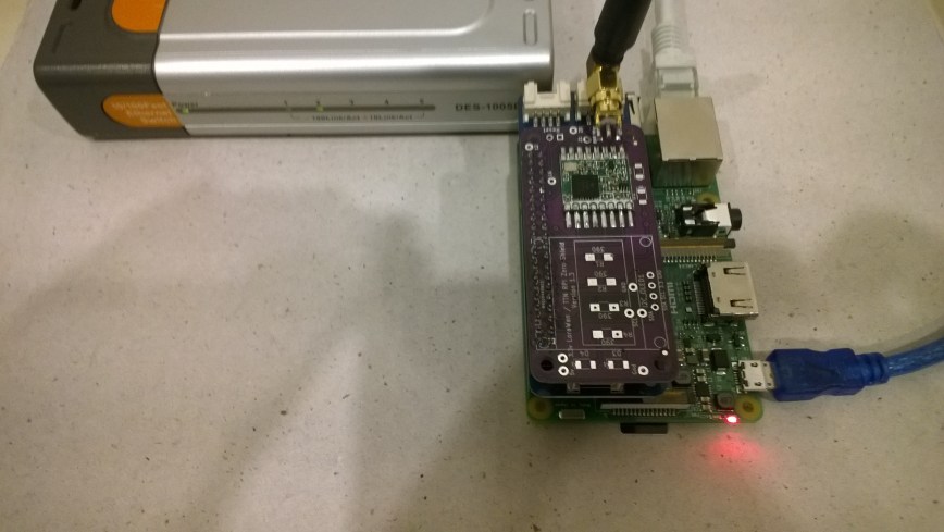
I had also purchased a Lora/LoRaWAN shield for Raspberry PI Zero and PI3 from Tindie (plus some unpopulated printed circuit boards so I can try building a RFM69HCW based shield).
The board didn’t fit on my Raspberry PI 2 & 3 devices so I used a Dexter industries Grove PI0 Shield as a temporary spacer to lift the antenna connector above the USB sockets.
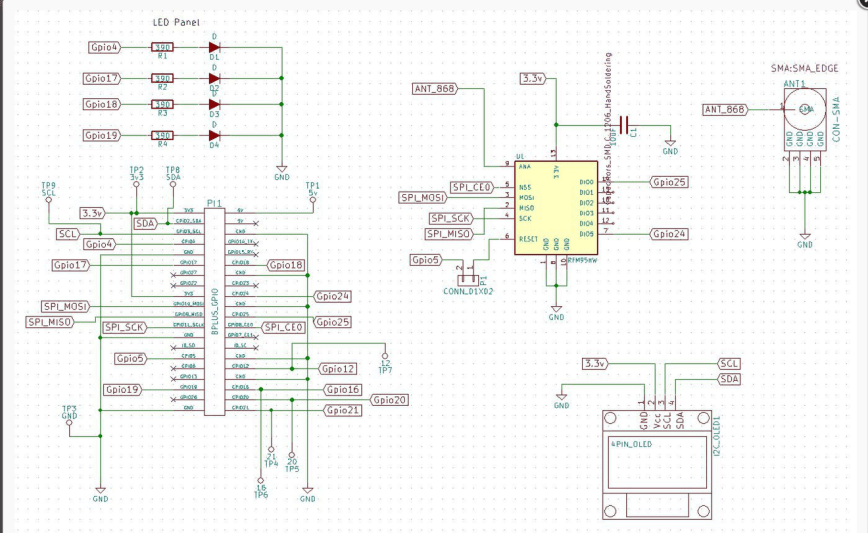
The RFM95 chip select line is connected to pin 24 (GPIO8), the reset line to pin 29(GPIO5) and the interrupt line (RFM95 DIO0) to pin 22(GPIO25).
My board doesn’t have any Light Emitting Diodes (LEDs) so it was straight into reading register values
//---------------------------------------------------------------------------------
// Copyright (c) July 2018, devMobile Software
//
// Licensed under the Apache License, Version 2.0 (the "License");
// you may not use this file except in compliance with the License.
// You may obtain a copy of the License at
//
//     http://www.apache.org/licenses/LICENSE-2.0
//
// Unless required by applicable law or agreed to in writing, software
// distributed under the License is distributed on an "AS IS" BASIS,
// WITHOUT WARRANTIES OR CONDITIONS OF ANY KIND, either express or implied.
// See the License for the specific language governing permissions and
// limitations under the License.
//
//---------------------------------------------------------------------------------
namespace devMobile.IoT.Rfm9x.ElectronicTricksSPI
{
	using System;
	using System.Diagnostics;
	using System.Threading;
	using Windows.ApplicationModel.Background;
	using Windows.Devices.Spi;

	public sealed class StartupTask : IBackgroundTask
	{
		public void Run(IBackgroundTaskInstance taskInstance)
		{
			SpiController spiController = SpiController.GetDefaultAsync().AsTask().GetAwaiter().GetResult();
			var settings = new SpiConnectionSettings(0) // GPIO8 Electronic Tricks
			{
				ClockFrequency = 500000,
				Mode = SpiMode.Mode0,   // From SemTech docs pg 80 CPOL=0, CPHA=0
			};

			SpiDevice Device = spiController.GetDevice(settings);

			while (true)
			{
				byte[] writeBuffer = new byte[] { 0x42 }; // RegVersion
				byte[] readBuffer = new byte[1];

				Device.TransferSequential(writeBuffer, readBuffer);

				byte registerValue = readBuffer[0];
				Debug.WriteLine("Register 0x{0:x2} - Value 0X{1:x2} - Bits {2}", 0x42, registerValue, Convert.ToString(registerValue, 2).PadLeft(8, '0'));

				Thread.Sleep(10000);
			}
		}
	}
}
The debug output confirmed I was reading the right value from the RegVer register
Register 0x42 - Value 0X12 - Bits 00010010
Register 0x42 - Value 0X12 - Bits 00010010
Register 0x42 - Value 0X12 - Bits 00010010
Register 0x42 - Value 0X12 - Bits 00010010
Register 0x42 - Value 0X12 - Bits 00010010
Register 0x42 - Value 0X12 - Bits 00010010
Register 0x42 - Value 0X12 - Bits 00010010
Register 0x42 - Value 0X12 - Bits 00010010
The antenna connector not clearing the USB socket is an issue which I’ll solve with a socket like the one on the GrovePI which has longer leads and acts as a spacer.
