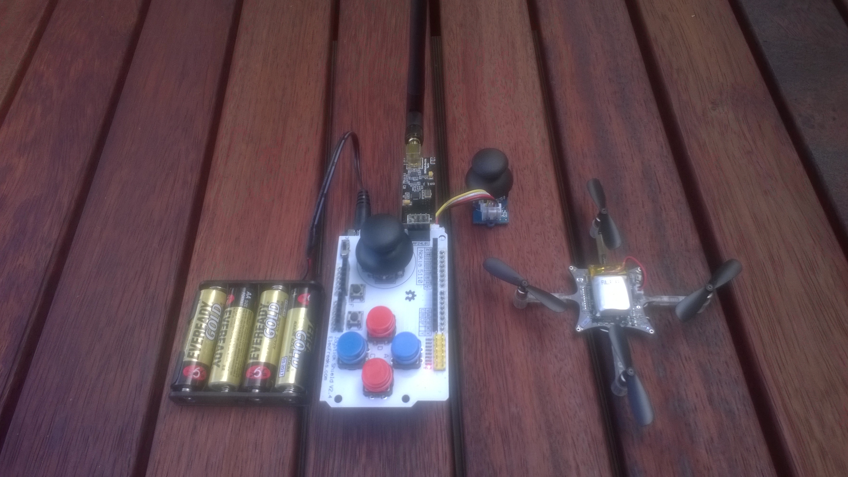
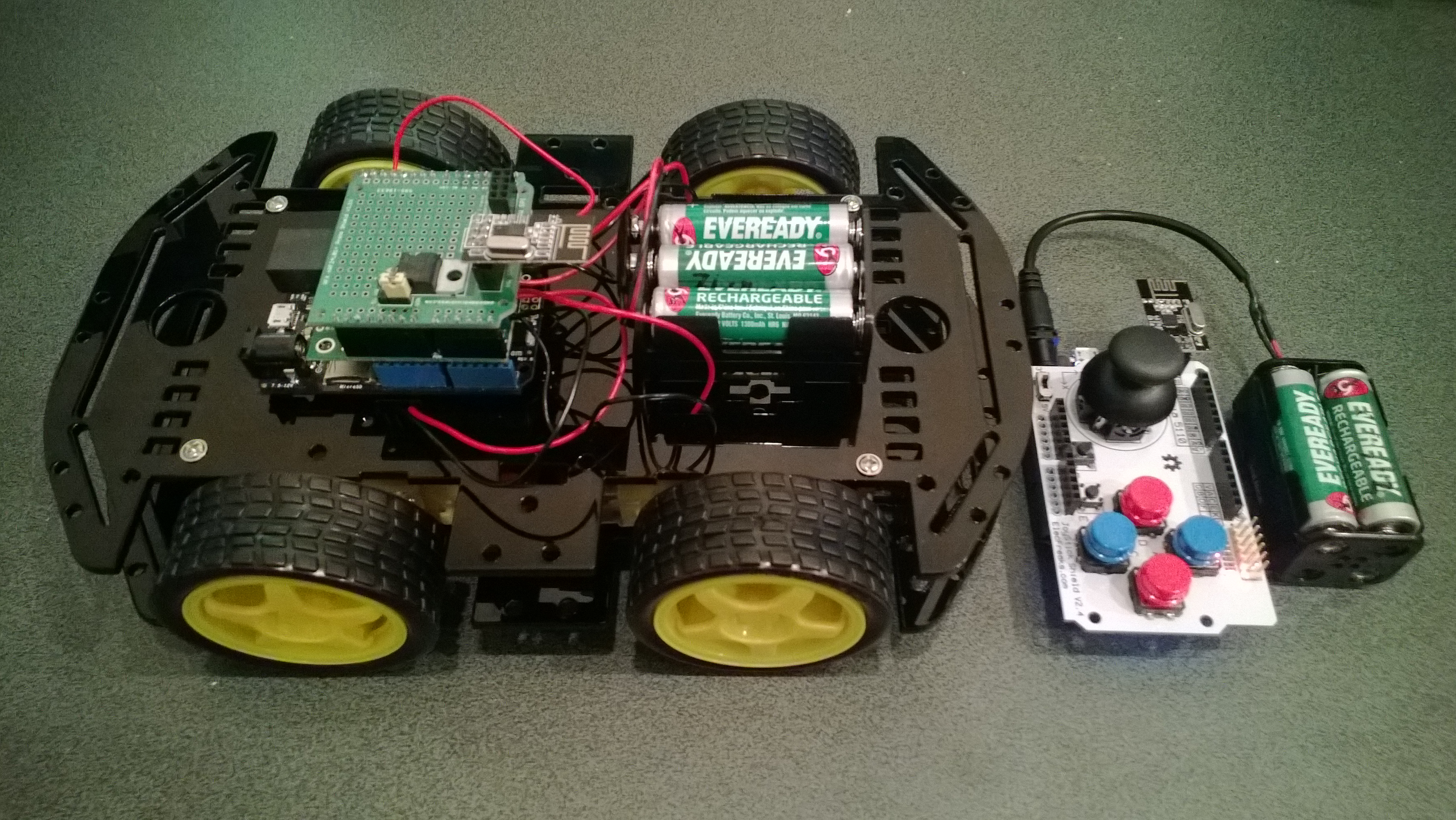
After flying the Crazyflie for a couple of days with the Joystick shield based remote control I figured an alternate user interface based on a Wii Nunchuk could be interesting. (It might also make the Crazyflie easier to operate for novice pilots). After a couple of hours coding I have a proof of concept Netduino based Crazyflie Nanocopter Wii Nunchck remote control unit.
Initially the nanocopter was difficult to fly, bouncing up and down (thrust control issues) and swaying side to side (roll & pitch control issues). After some digging I found that every so often the Wii nunchuk (my cheap clone) would return a buffer full of 0xFF or 0x00 bytes. The 0xFF case had been handled but not the 0x00 one. I added a second test into the GetData method (around line 335) to catch the 0x00 scenario and this appeared to fix the problem.
cnt = 0;
for (int i = 0; i < inputBuffer.Length; i++)
   if (inputBuffer[i] == 0x0) cnt++;
if (cnt == inputBuffer.Length)
{
   return false;
}
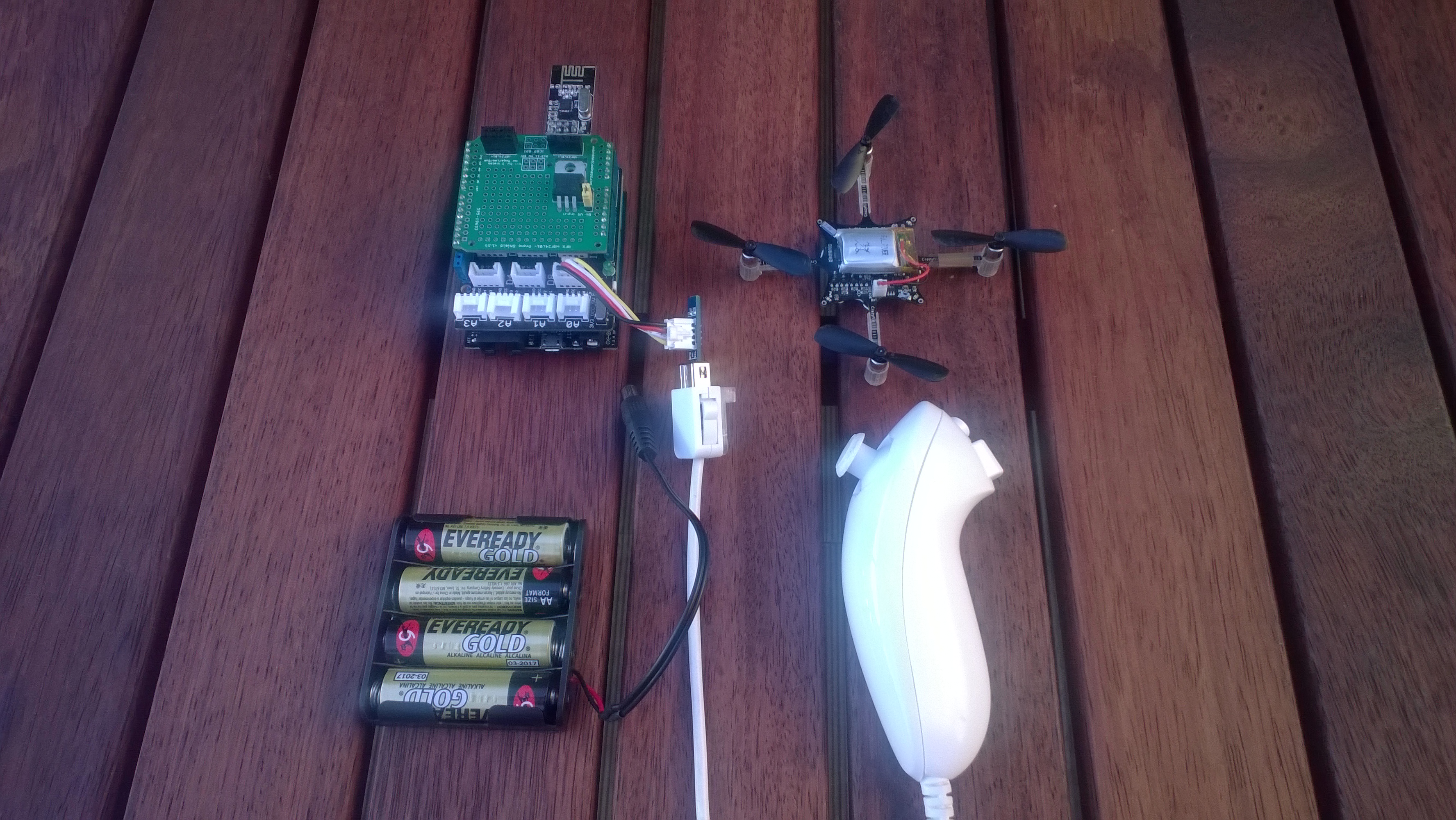
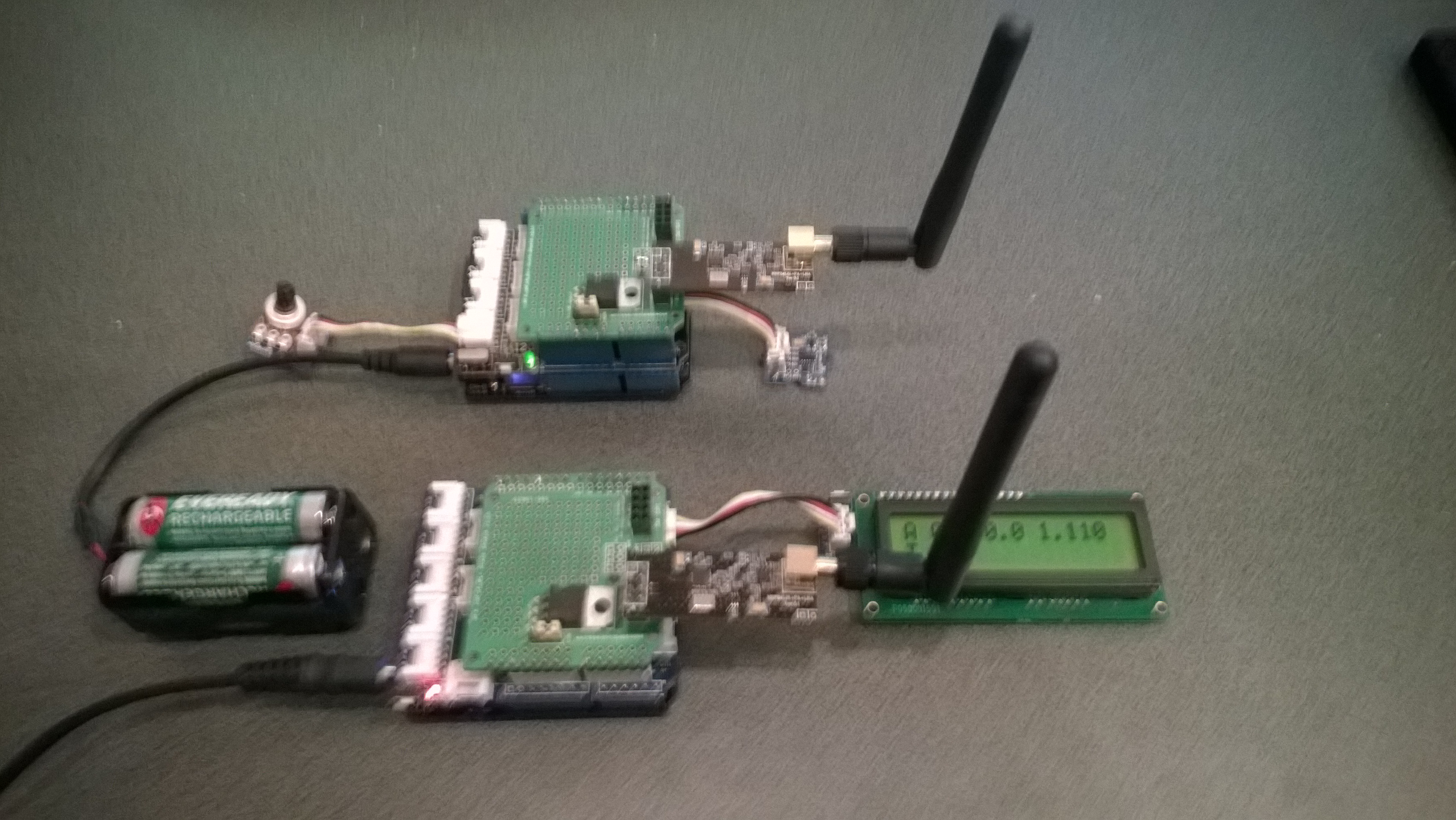
CrazyFlie Netduino Wiichuck based Remote
Bill on Materials (Prices as at Jan 2014)
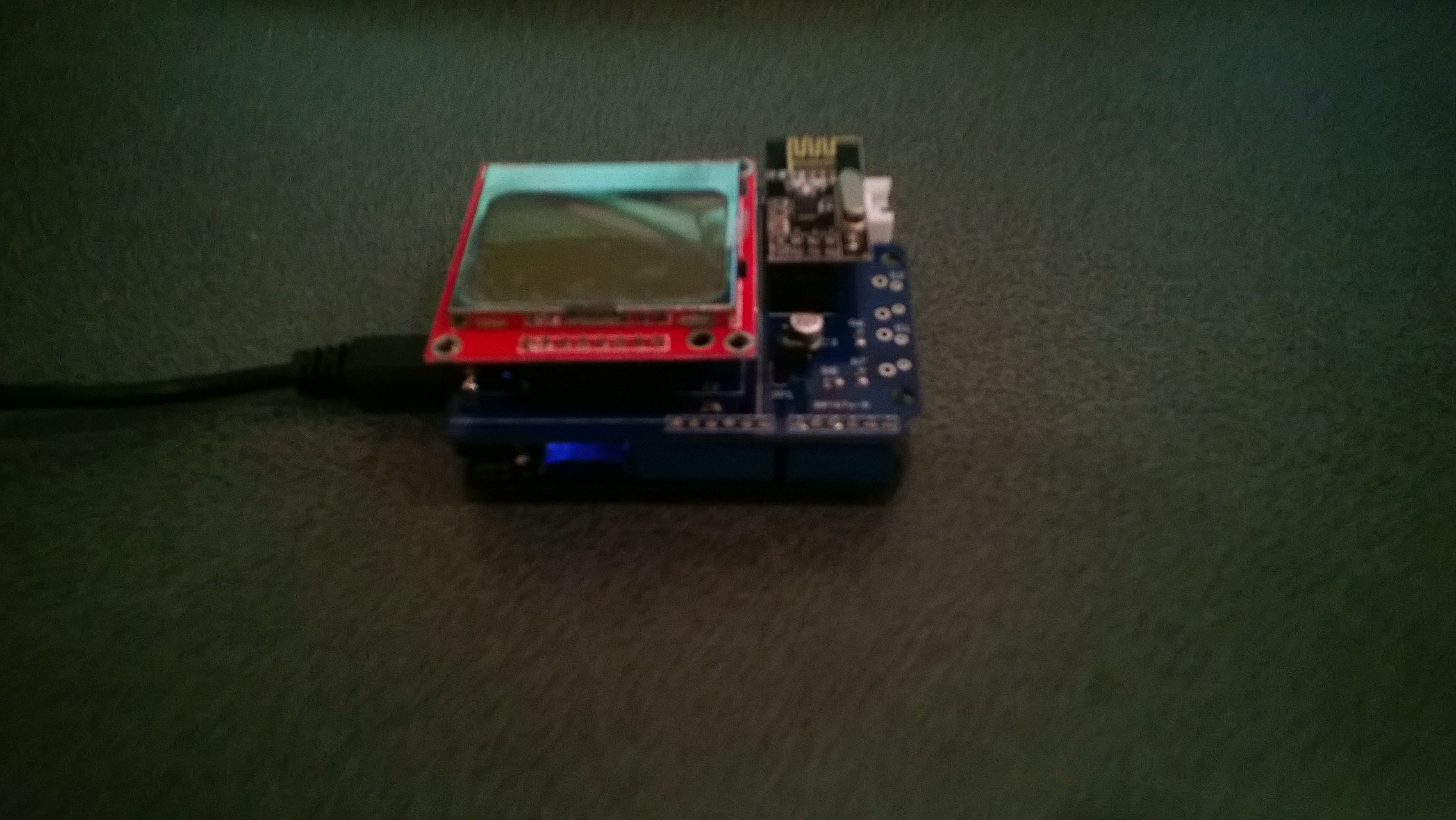
- Netduino 2 USD 32.94 NZD 59.63
- Grove Base Shield V2 USD 8.90
- Grove Nunchuck adaptor USD 2.90
- Grove 5CM cables USD 1.90
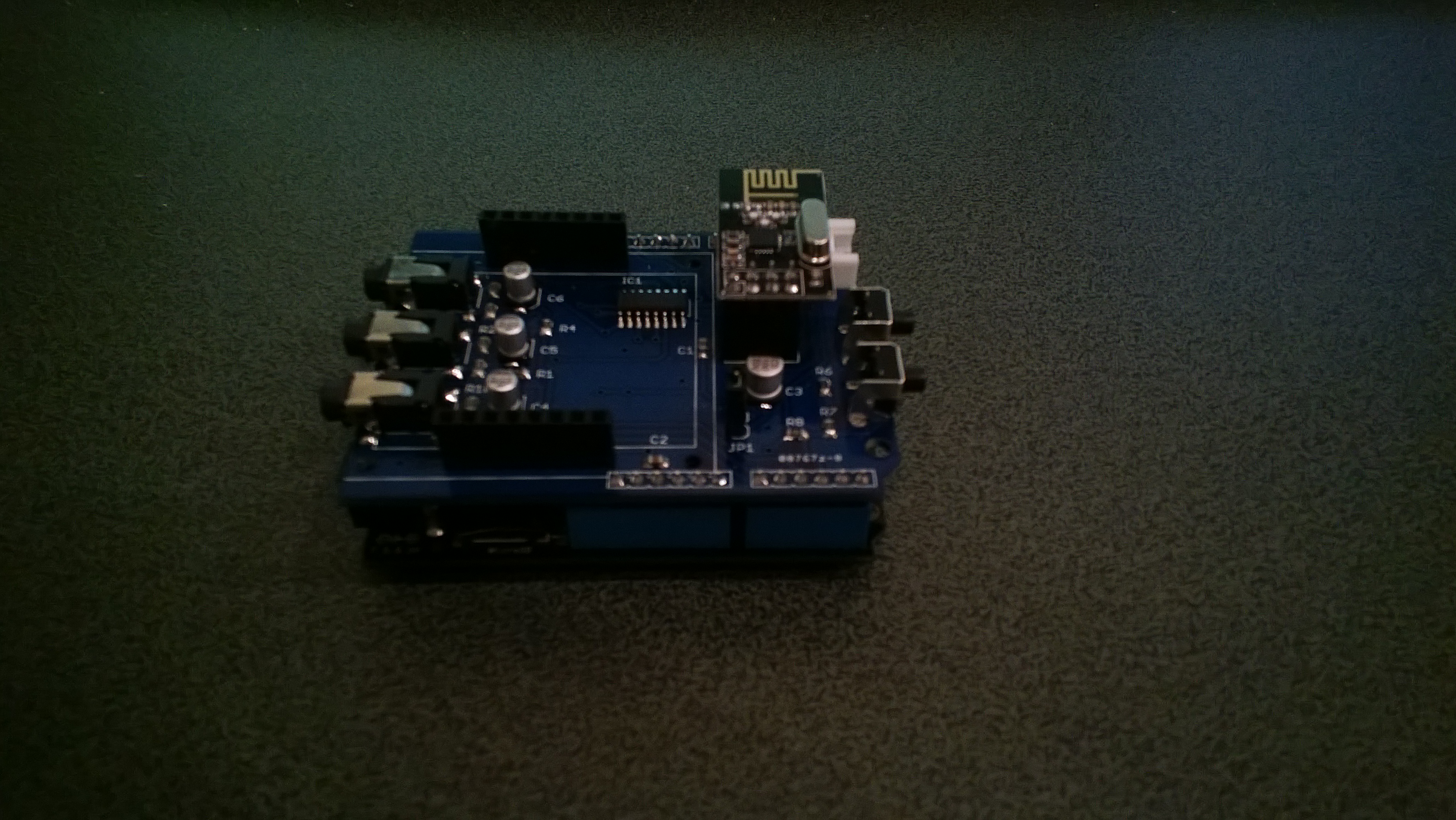
- Embedded coolness RFX Arduino nRF24L01 Shield AUD 7.90
This software was built using tooling created and shared by others.
Big thanks to
Jakub Bartkowiak – Gralin.NETMF.Nordic.NRF24L01Plus
Szymon Kobalczyk – Wiichuck I2C driver
Antao Almada – HydraMF.BitConverter
The nunchuck accelerometer provides roll and pitch, the joystick is for thrust and yaw. The first version of the CrazyFlieWiiChuckV1.0 is pretty basic and I have intentionally reduced the maximum roll, pitch, thrust and yaw values to make it easier to fly. (Need to set the Grove Base Shield to 3V3 for my code to work)
Currently I only calculate offset values for thrust & yaw. After a couple of test flights some visual indication of the pitch and roll values from the nunchuk would be helpfull.