Random wanderings through Microsoft Azure esp. PaaS plumbing, the IoT bits, AI on Micro controllers, AI on Edge Devices, .NET nanoFramework, .NET Core on *nix and ML.NET+ONNX
// Set the Working mode to LoRaWAN, not/never going todo P2P with this library.
#if DIAGNOSTICS
Debug.WriteLine($" {DateTime.UtcNow:hh:mm:ss} AT+NWM=1");
#endif
Result result = SendCommand("Current Work Mode: LoRaWAN.", "AT+NWM=1", CommandTimeoutDefault);
if (result != Result.Success)
{
#if DIAGNOSTICS
	Debug.WriteLine($" {DateTime.UtcNow:hh:mm:ss} AT+NWM=1 failed {result}");
#endif
	return result;
}
I think it would be reasonable to assume that the device is in the correct mode (the default after a reset to factory) on startup so I removed the LoRa® network work mode configuration code.
//---------------------------------------------------------------------------------
// Copyright (c) August 2022, devMobile Software
//
// Licensed under the Apache License, Version 2.0 (the "License");
// you may not use this file except in compliance with the License.
// You may obtain a copy of the License at
//
// http://www.apache.org/licenses/LICENSE-2.0
//
// Unless required by applicable law or agreed to in writing, software
// distributed under the License is distributed on an "AS IS" BASIS,
// WITHOUT WARRANTIES OR CONDITIONS OF ANY KIND, either express or implied.
// See the License for the specific language governing permissions and
// limitations under the License.
//
// RAK Core WisBlock
// https://docs.rakwireless.com/Product-Categories/WisBlock/RAK11200
//
// RAK WisBlock Wireless
// https://docs.rakwireless.com/Product-Categories/WisBlock/RAK2305/Overview/
//
// RAK WisBlock Bases
// https://docs.rakwireless.com/Product-Categories/WisBlock/RAK5005-O
// https://docs.rakwireless.com/Product-Categories/WisBlock/RAK19001
//
// RAK WisBlock Sensor
// https://docs.rakwireless.com/Product-Categories/WisBlock/RAK1910
//
// Uses the library
// https://github.com/mboud/TinyGPSPlusNF
//
// Inspired by
// https://github.com/RAKWireless/WisBlock/tree/master/examples/common/sensors/RAK1910_GPS_UBLOX7
//
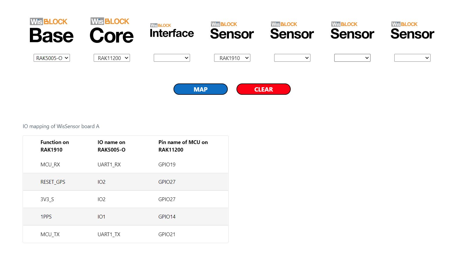
// Pins mapped with
// https://docs.rakwireless.com/Knowledge-Hub/Pin-Mapper/
//
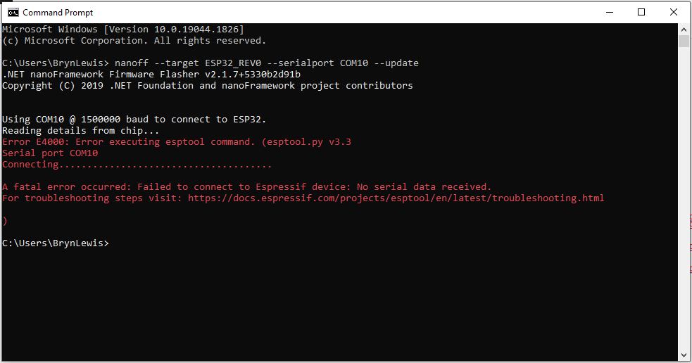
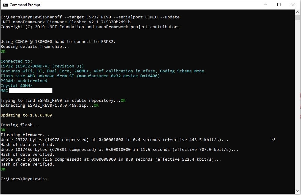
// Flash device with
// nanoff --target ESP32_REV0 --serialport COM16 --update
//
//---------------------------------------------------------------------------------
namespace devMobile.IoT.RAK.Wisblock.RAK1910
{
using System;
using System.Device.Gpio;
using System.Diagnostics;
using System.IO.Ports;
using System.Threading;
using nanoFramework.Hardware.Esp32;
using TinyGPSPlusNF;
public class Program
{
private static TinyGPSPlus _gps;
public static void Main()
{
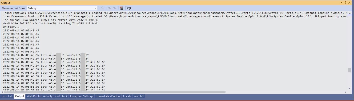
Debug.WriteLine($"devMobile.IoT.RAK.Wisblock.RAK1910 starting TinyGPS {TinyGPSPlus.LibraryVersion}");
try
{
#if RAK11200
Configuration.SetPinFunction(Gpio.IO21, DeviceFunction.COM2_TX);
Configuration.SetPinFunction(Gpio.IO19, DeviceFunction.COM2_RX);
#endif
#if RAK2350
Configuration.SetPinFunction(Gpio.IO21, DeviceFunction.COM2_RX);
Configuration.SetPinFunction(Gpio.IO19, DeviceFunction.COM2_TX);
#endif
_gps = new TinyGPSPlus();
// UART1 with default Max7Q baudrate
SerialPort serialPort = new SerialPort("COM2", 9600);
serialPort.DataReceived += SerialDevice_DataReceived;
serialPort.Open();
serialPort.WatchChar = '\n';
// Enable the GPS module GPS 3V3_S/RESET_GPS - IO2 - GPIO27
GpioController gpioController = new GpioController();
GpioPin Gps3V3 = gpioController.OpenPin(Gpio.IO27, PinMode.Output);
Gps3V3.Write(PinValue.High);
Debug.WriteLine("Waiting...");
Thread.Sleep(Timeout.Infinite);
}
catch (Exception ex)
{
Debug.WriteLine($"UBlox MAX7Q initialisation failed {ex.Message}");
Thread.Sleep(Timeout.Infinite);
}
}
private static void SerialDevice_DataReceived(object sender, SerialDataReceivedEventArgs e)
{
// we only care if got EoL character
if (e.EventType != SerialData.WatchChar)
{
return;
}
SerialPort serialDevice = (SerialPort)sender;
string sentence = serialDevice.ReadExisting();
if (_gps.Encode(sentence))
{
if (_gps.Date.IsValid)
{
Debug.Write($"{_gps.Date.Year}-{_gps.Date.Month:D2}-{_gps.Date.Day:D2} ");
}
if (_gps.Time.IsValid)
{
Debug.Write($"{_gps.Time.Hour:D2}:{_gps.Time.Minute:D2}:{_gps.Time.Second:D2}.{_gps.Time.Centisecond:D2} ");
}
if (_gps.Location.IsValid)
{
Debug.Write($"Lat:{_gps.Location.Latitude.Degrees:F5}° Lon:{_gps.Location.Longitude.Degrees:F5}° ");
}
if (_gps.Altitude.IsValid)
{
Debug.Write($"Alt:{_gps.Altitude.Meters:F1}M ");
}
if (_gps.Location.IsValid)
{
Debug.Write($"Hdop:{_gps.Hdop.Value:F2}");
}
if (_gps.Date.IsValid || _gps.Time.IsValid || _gps.Location.IsValid || _gps.Altitude.IsValid)
{
Debug.WriteLine("");
}
}
}
}
}
After some experimentation I found that serial port TX/RX lines had to be reversed because both devices would normally be connected to a WisBlock core module.
//---------------------------------------------------------------------------------
// Copyright (c) September 2022, devMobile Software
//
// Licensed under the Apache License, Version 2.0 (the "License");
// you may not use this file except in compliance with the License.
// You may obtain a copy of the License at
//
// http://www.apache.org/licenses/LICENSE-2.0
//
// Unless required by applicable law or agreed to in writing, software
// distributed under the License is distributed on an "AS IS" BASIS,
// WITHOUT WARRANTIES OR CONDITIONS OF ANY KIND, either express or implied.
// See the License for the specific language governing permissions and
// limitations under the License.
//
// https://docs.rakwireless.com/Product-Categories/WisBlock/RAK2305
//
// https://docs.rakwireless.com/Product-Categories/WisBlock/RAK11200
//
// https://store.rakwireless.com/products/rak1901-shtc3-temperature-humidity-sensor
//
// https://github.com/nanoframework/nanoFramework.IoT.Device/tree/develop/devices/Shtc3
//
//---------------------------------------------------------------------------------
namespace devMobile.IoT.RAK.Wisblock.RAK1901
{
using System;
using System.Diagnostics;
using System.Device.I2c;
using System.Threading;
using nanoFramework.Hardware.Esp32;
using Iot.Device.Shtc3;
public class Program
{
public static void Main()
{
Debug.WriteLine("devMobile.IoT.RAK.Wisblock.RAK11200RAK1901 starting");
try
{
// RAK11200 & RAK2305
                Configuration.SetPinFunction(Gpio.IO04, DeviceFunction.I2C1_DATA);
Configuration.SetPinFunction(Gpio.IO05, DeviceFunction.I2C1_CLOCK);
I2cConnectionSettings settings = new(1, Shtc3.DefaultI2cAddress);
using (I2cDevice device = I2cDevice.Create(settings))
using (Shtc3 shtc3 = new(device))
{
while (true)
{
if (shtc3.TryGetTemperatureAndHumidity(out var temperature, out var relativeHumidity))
{
Debug.WriteLine($"Temperature {temperature.DegreesCelsius:F1}°C Humidity {relativeHumidity.Value:F0}%");
}
Thread.Sleep(10000);
}
}
}
catch (Exception ex)
{
Debug.WriteLine($"SHTC3 initialisation or read failed {ex.Message}");
Thread.Sleep(Timeout.Infinite);
}
}
}
}
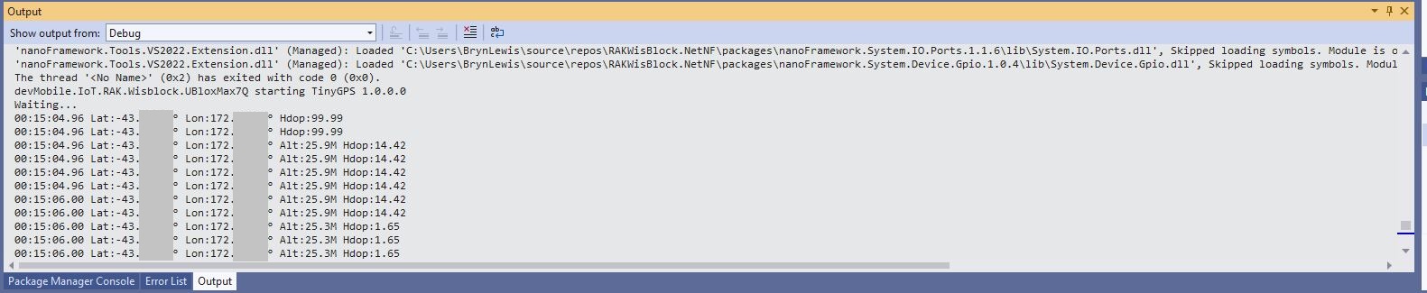
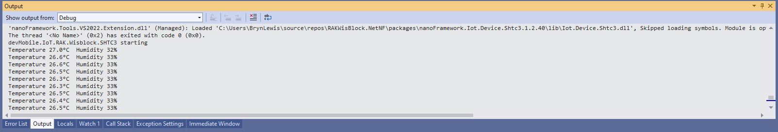
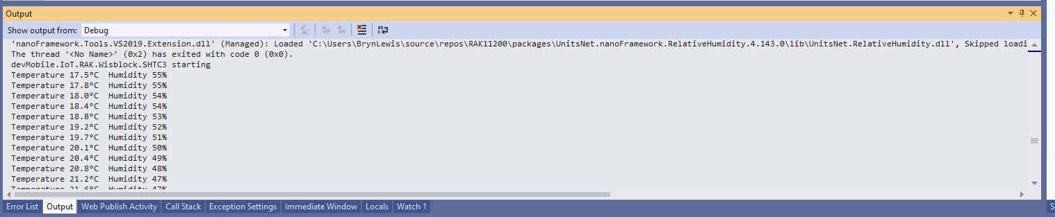
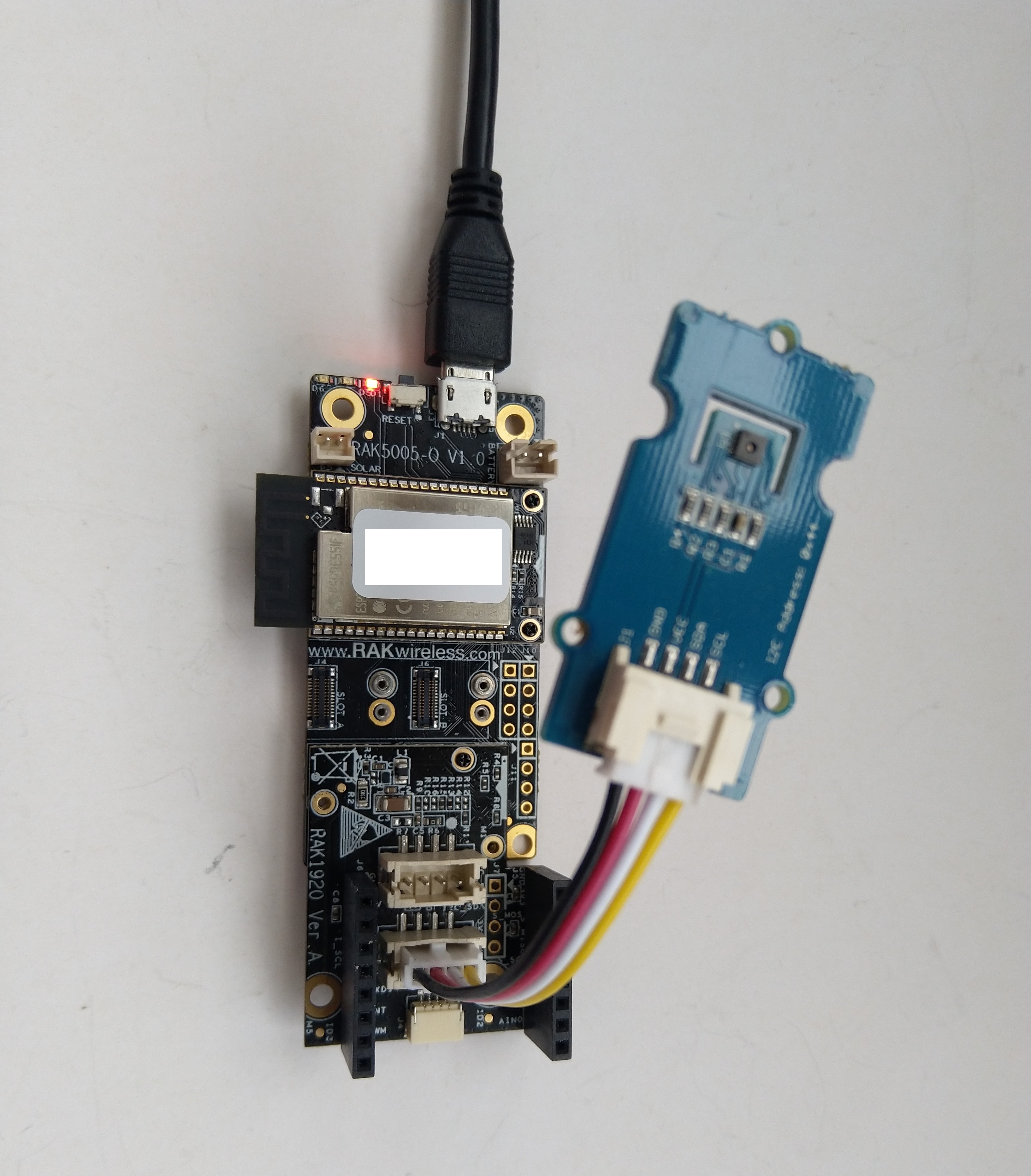
Visual Studio Output window displaying SHT31 temperature & humidity values
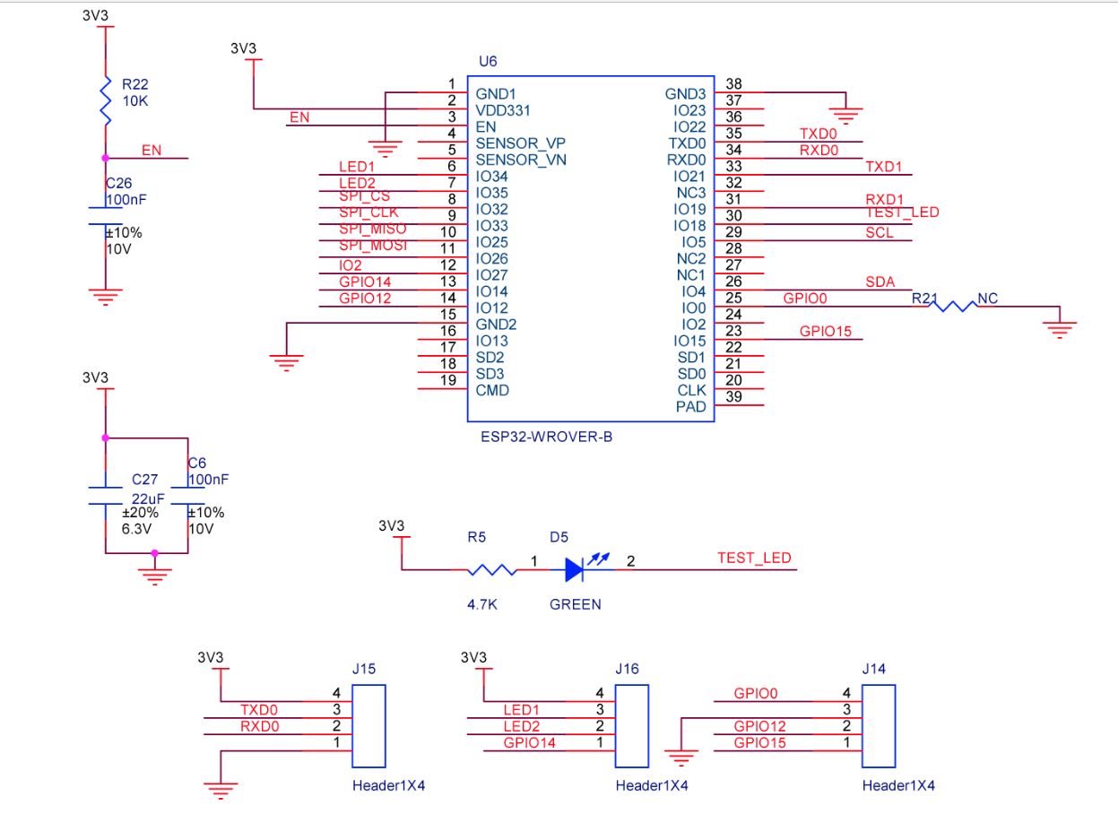
The RAK2305 Low Level Developer documentation described how to upload software developed with the Arduino tools by putting the ESP32 into “bootloader mode”. This is done by connecting (with the white jumper) the GPIO0 and GND pins on J14, and pressing the reset button.
The RAK2305 has has one onboard LED(TEST_LED) attached to IO18 which I added to the .NET nanoFrameworkBlinky sample.
//
// Copyright (c) .NET Foundation and Contributors
// See LICENSE file in the project root for full license information.
//
//
using System;
using System.Device.Gpio;
using System.Threading;
using nanoFramework.Hardware.Esp32;

namespace Blinky
{
   public class Program
   {
      private static GpioController s_GpioController;

      public static void Main()
      {
         s_GpioController = new GpioController();

         // pick a board, uncomment one line for GpioPin; default is STM32F769I_DISCO

         // DISCOVERY4: PD15 is LED6
         //GpioPin led = s_GpioController.OpenPin(PinNumber('D', 15), PinMode.Output);

         // ESP32 DevKit: 4 is a valid GPIO pin in, some boards like Xiuxin ESP32 may require GPIO Pin 2 instead.
         //GpioPin led = s_GpioController.OpenPin(4, PinMode.Output);

         // FEATHER S2:
         //GpioPin led = s_GpioController.OpenPin(13, PinMode.Output);

         // F429I_DISCO: PG14 is LEDLD4
         //GpioPin led = s_GpioController.OpenPin(PinNumber('G', 14), PinMode.Output);

         // NETDUINO 3 Wifi: A10 is LED onboard blue
         //GpioPin led = s_GpioController.OpenPin(PinNumber('A', 10), PinMode.Output);

         // QUAIL: PE15 is LED1
         //GpioPin led = s_GpioController.OpenPin(PinNumber('E', 15), PinMode.Output);

         // STM32F091RC: PA5 is LED_GREEN
         //GpioPin led = s_GpioController.OpenPin(PinNumber('A', 5), PinMode.Output);

         // STM32F746_NUCLEO: PB75 is LED2
         //GpioPin led = s_GpioController.OpenPin(PinNumber('B', 7), PinMode.Output);

         //STM32F769I_DISCO: PJ5 is LD2
         //GpioPin led = s_GpioController.OpenPin(PinNumber('J', 5), PinMode.Output);

         // ST_B_L475E_IOT01A: PB14 is LD2
         //GpioPin led = s_GpioController.OpenPin(PinNumber('B', 14), PinMode.Output);

         // STM32L072Z_LRWAN1: PA5 is LD2
         //GpioPin led = s_GpioController.OpenPin(PinNumber('A', 5), PinMode.Output);

         // TI CC13x2 Launchpad: DIO_07 it's the green LED
         //GpioPin led = s_GpioController.OpenPin(7, PinMode.Output);

         // TI CC13x2 Launchpad: DIO_06 it's the red LED
         //GpioPin led = s_GpioController.OpenPin(6, PinMode.Output);

         // ULX3S FPGA board: for the red D22 LED from the ESP32-WROOM32, GPIO5
         //GpioPin led = s_GpioController.OpenPin(5, PinMode.Output);

         // Silabs SLSTK3701A: LED1 PH14 is LLED1
         //GpioPin led = s_GpioController.OpenPin(PinNumber('H', 14), PinMode.Output);

         // RAK11200 on RAK5005
         //GpioPin led = s_GpioController.OpenPin(Gpio.IO12, PinMode.Output); // LED1 Green
         //GpioPin led = s_GpioController.OpenPin(Gpio.IO02, PinMode.Output); // LED2 Blue

         // RAK11200 on RAK19001 needs battery connected or power switch in rechargeable position.
         //GpioPin led = s_GpioController.OpenPin(Gpio.IO12, PinMode.Output); // LED1 Green
         //GpioPin led = s_GpioController.OpenPin(Gpio.IO02, PinMode.Output); // LED2 Blue

         // RAK2305
         //GpioPin led = s_GpioController.OpenPin(Gpio.IO18, PinMode.Output); // LED Green (Test LED) on device

         // RAK2305 On 5005 throws exceptions
         //GpioPin led = s_GpioController.OpenPin(Gpio.IO34, PinMode.Output); // LED1 Green
         //GpioPin led = s_GpioController.OpenPin(Gpio.IO35, PinMode.Output); // LED2 Blue

         // RAK2305 On 17001 throws exceptions
         //GpioPin led = s_GpioController.OpenPin(Gpio.IO34, PinMode.Output); // LED1 Green
         //GpioPin led = s_GpioController.OpenPin(Gpio.IO35, PinMode.Output); // LED2 Blue

         led.Write(PinValue.Low);

         while (true)
         {
            led.Toggle();
            Thread.Sleep(125);
            led.Toggle();
            Thread.Sleep(125);
            led.Toggle();
            Thread.Sleep(125);
            led.Toggle();
            Thread.Sleep(525);
         }
      }

      static int PinNumber(char port, byte pin)
      {
         if (port < 'A' || port > 'J')
            throw new ArgumentException();

         return ((port - 'A') * 16) + pin;
      }
   }
}
I added the RAK2305 configuration to my version of the nanoFramework Blinky sample and could reliably flash the onboard LED.
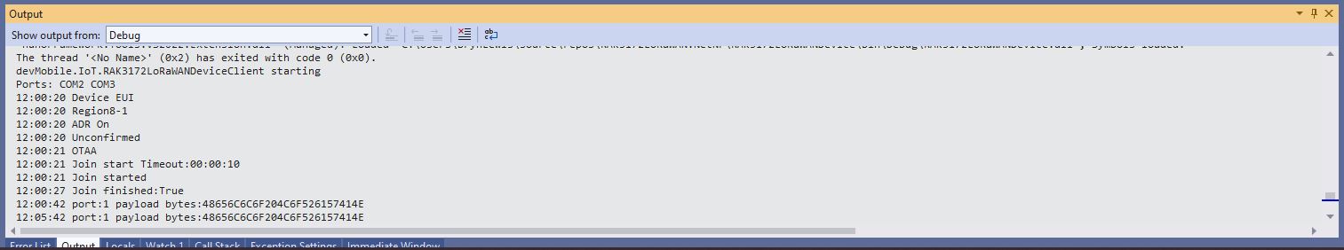
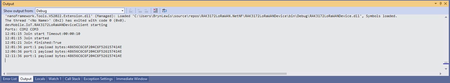
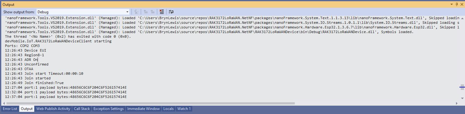
Visual Studio Debug output for RAK3172LoRaWANDeviceClient minimal configuration
public static void Main()
{
	Result result;

	Debug.WriteLine("devMobile.IoT.RAK3172LoRaWANDeviceClient starting");

	try
	{
		// set GPIO functions for COM2 (this is UART1 on ESP32)
#if ESP32_WROOM
		Configuration.SetPinFunction(Gpio.IO17, DeviceFunction.COM2_TX);
		Configuration.SetPinFunction(Gpio.IO16, DeviceFunction.COM2_RX);
#endif

		Debug.Write("Ports:");
		foreach (string port in SerialPort.GetPortNames())
		{
			Debug.Write($" {port}");
		}
		Debug.WriteLine("");

		using (Rak3172LoRaWanDevice device = new Rak3172LoRaWanDevice())
		{
			result = device.Initialise(SerialPortId, 115200, Parity.None, 8, StopBits.One);
			if (result != Result.Success)
			{
				Debug.WriteLine($"Initialise failed {result}");
				return;
			}

			MessageSendTimer = new Timer(SendMessageTimerCallback, device, Timeout.Infinite, Timeout.Infinite);

			device.OnJoinCompletion += OnJoinCompletionHandler;
			device.OnReceiveMessage += OnReceiveMessageHandler;
#if CONFIRMED
			device.OnMessageConfirmation += OnMessageConfirmationHandler;
#endif

#if FACTORY_RESET
			Debug.WriteLine($"{DateTime.UtcNow:hh:mm:ss} FactoryReset");
			result = device.FactoryReset();
			if (result != Result.Success)
			{
				Debug.WriteLine($"FactoryReset failed {result}");
				return;
			}
#endif

#if DEVICE_DEVEUI_SET
			Debug.WriteLine($"{DateTime.UtcNow:hh:mm:ss} Device EUI");
			result = device.DeviceEui(Config.devEui);
			if (result != Result.Success)
			{
				Debug.WriteLine($"DeviceEUI set failed {result}");
				return;
			}
#endif

#if REGION_SET
			Debug.WriteLine($"{DateTime.UtcNow:hh:mm:ss} Region{Band}");
			result = device.Band(Band);
			if (result != Result.Success)
			{
				Debug.WriteLine($"Band on failed {result}");
				return;
			}
#endif

#if ADR_SET
			Debug.WriteLine($"{DateTime.UtcNow:hh:mm:ss} ADR On");
			result = device.AdrOn();
			if (result != Result.Success)
			{
				Debug.WriteLine($"ADR on failed {result}");
				return;
			}
#endif
#if CONFIRMED
			Debug.WriteLine($"{DateTime.UtcNow:hh:mm:ss} Confirmed");
			result = device.UplinkMessageConfirmationOn();
			if (result != Result.Success)
			{
				Debug.WriteLine($"Confirm on failed {result}");
				return;
			}
#endif
#if UNCONFIRMED
			Debug.WriteLine($"{DateTime.UtcNow:hh:mm:ss} Unconfirmed");
			result = device.UplinkMessageConfirmationOff();
			if (result != Result.Success)
			{
				Debug.WriteLine($"Confirm off failed {result}");
				return;
			}
#endif

#if OTAA
			Debug.WriteLine($"{DateTime.UtcNow:hh:mm:ss} OTAA");
			result = device.OtaaInitialise(Config.JoinEui, Config.AppKey);
			if (result != Result.Success)
			{
				Debug.WriteLine($"OTAA Initialise failed {result}");
				return;
			}
#endif

#if ABP
			Debug.WriteLine($"{DateTime.UtcNow:hh:mm:ss} ABP");
			result = device.AbpInitialise(Config.DevAddress, Config.NwksKey, Config.AppsKey);
			if (result != Result.Success)
			{
				Debug.WriteLine($"ABP Initialise failed {result}");
				return;
			}
#endif

			Debug.WriteLine($"{DateTime.UtcNow:hh:mm:ss} Join start Timeout:{JoinTimeOut:hh:mm:ss}");
			result = device.Join(JoinTimeOut);
			if (result != Result.Success)
			{
				Debug.WriteLine($"Join failed {result}");
				return;
			}
			Debug.WriteLine($"{DateTime.UtcNow:hh:mm:ss} Join started");

			Thread.Sleep(Timeout.Infinite);
		}
	}
	catch (Exception ex)
	{
		Debug.WriteLine(ex.Message);
	}
}
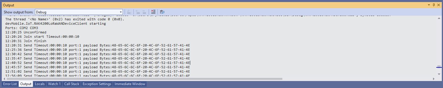
One of the major differences between the RAK4200 and RAK3127 libraries is the way a LoRaWAN network join is handled. The RAK4200 library Join method blocks until it succeeds of fails, the RAK3172 library Join method returns immediately then an EventHandler is called with the result.
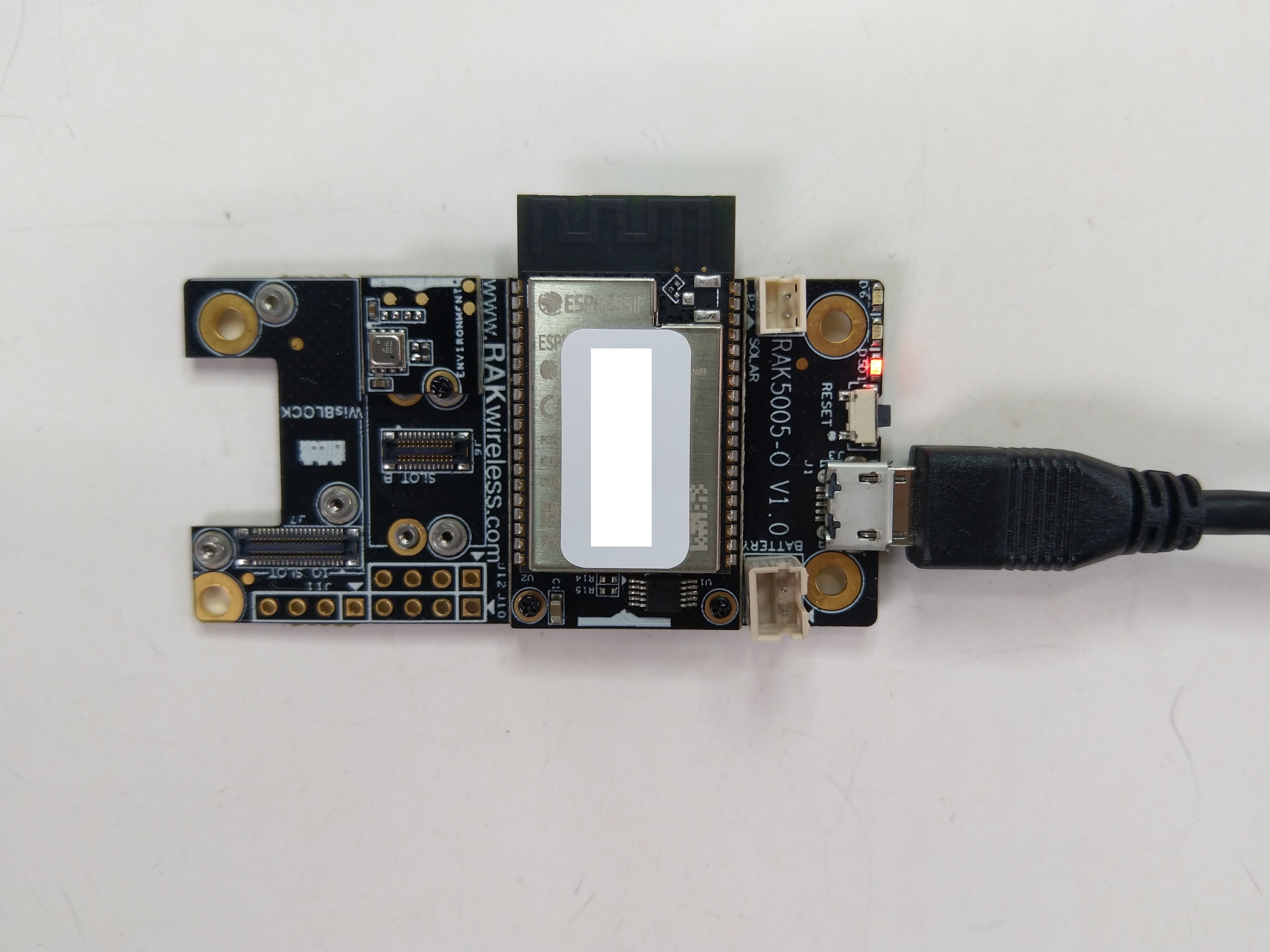
The RAK11200 documentation described how to upload software developed with the Arduino tools by putting the ESP32 into “bootloader mode” by connecting the BOOT0 and GND pins, then pressing the reset button.
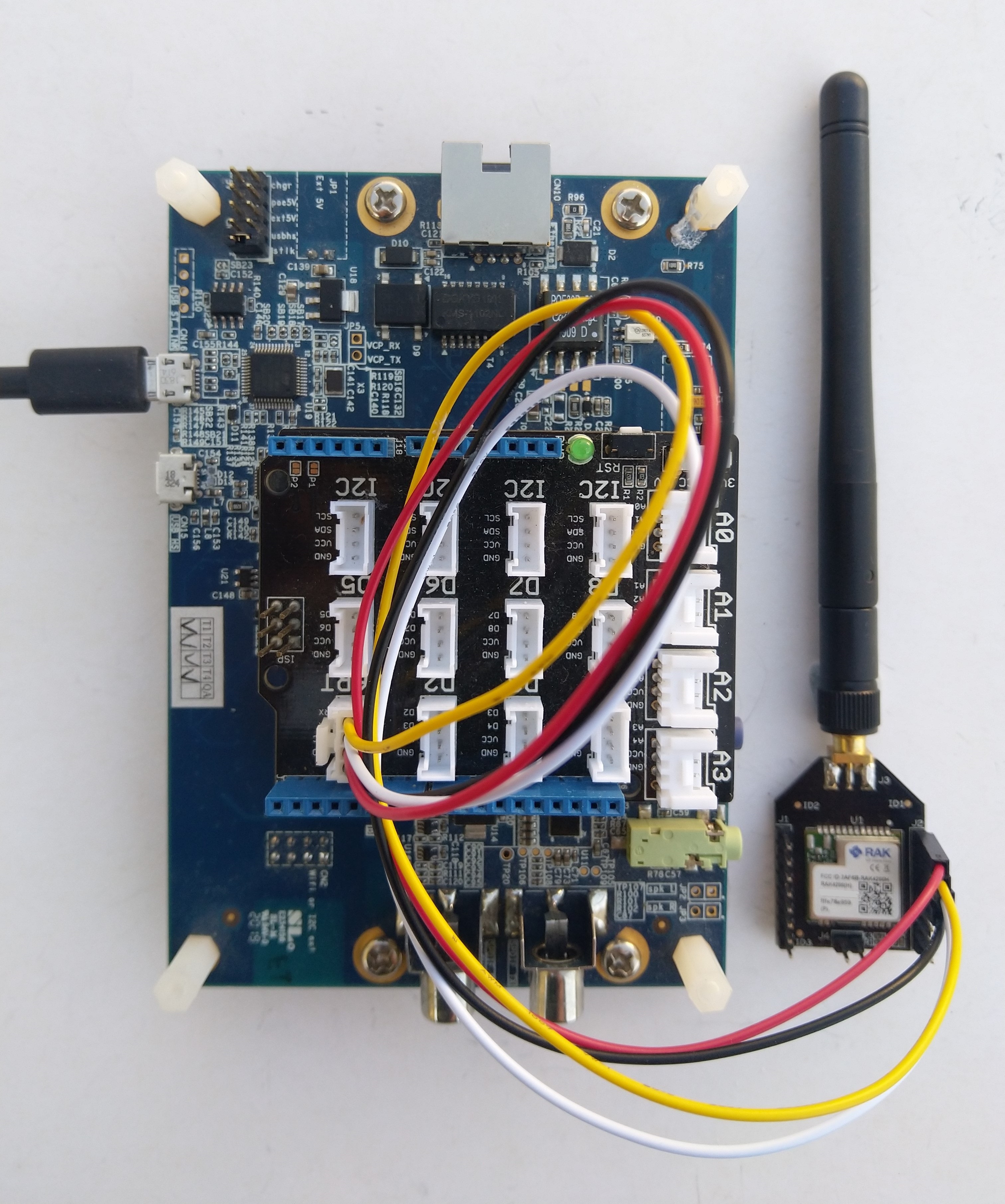
RAK11200 BOOT0 & GND pins connected to
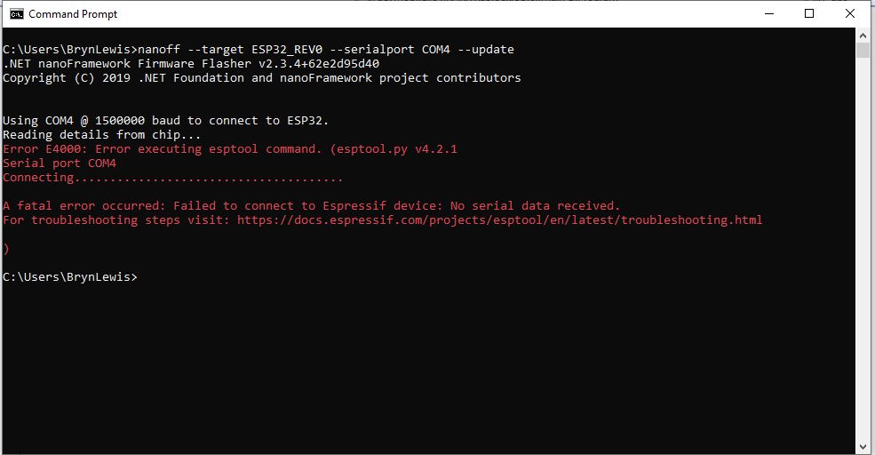
After some “trial and error” the download process worked pretty reliably…
The RAK11200 has two LEDs, a blue attached to IO02 and a green one attached to IO12.
//
// Copyright (c) .NET Foundation and Contributors
// See LICENSE file in the project root for full license information.
//
//
using System;
using System.Device.Gpio;
using System.Threading;
using nanoFramework.Hardware.Esp32;

namespace Blinky
{
   public class Program
   {
      private static GpioController s_GpioController;
      public static void Main()
      {
         s_GpioController = new GpioController();

         // pick a board, uncomment one line for GpioPin; default is STM32F769I_DISCO

         // DISCOVERY4: PD15 is LED6
         //GpioPin led = s_GpioController.OpenPin(PinNumber('D', 15), PinMode.Output);

         // ESP32 DevKit: 4 is a valid GPIO pin in, some boards like Xiuxin ESP32 may require GPIO Pin 2 instead.
         //GpioPin led = s_GpioController.OpenPin(4, PinMode.Output);

         // FEATHER S2:
         //GpioPin led = s_GpioController.OpenPin(13, PinMode.Output);

         // F429I_DISCO: PG14 is LEDLD4
         //GpioPin led = s_GpioController.OpenPin(PinNumber('G', 14), PinMode.Output);

         // NETDUINO 3 Wifi: A10 is LED onboard blue
         //GpioPin led = s_GpioController.OpenPin(PinNumber('A', 10), PinMode.Output);

         // QUAIL: PE15 is LED1
         //GpioPin led = s_GpioController.OpenPin(PinNumber('E', 15), PinMode.Output);

         // STM32F091RC: PA5 is LED_GREEN
         //GpioPin led = s_GpioController.OpenPin(PinNumber('A', 5), PinMode.Output);

         // STM32F746_NUCLEO: PB75 is LED2
         //GpioPin led = s_GpioController.OpenPin(PinNumber('B', 7), PinMode.Output);

         //STM32F769I_DISCO: PJ5 is LD2
         //GpioPin led = s_GpioController.OpenPin(PinNumber('J', 5), PinMode.Output);

         // ST_B_L475E_IOT01A: PB14 is LD2
         //GpioPin led = s_GpioController.OpenPin(PinNumber('B', 14), PinMode.Output);

         // STM32L072Z_LRWAN1: PA5 is LD2
         //GpioPin led = s_GpioController.OpenPin(PinNumber('A', 5), PinMode.Output);

         // TI CC13x2 Launchpad: DIO_07 it's the green LED
         //GpioPin led = s_GpioController.OpenPin(7, PinMode.Output);

         // TI CC13x2 Launchpad: DIO_06 it's the red LED
         //GpioPin led = s_GpioController.OpenPin(6, PinMode.Output);

         // ULX3S FPGA board: for the red D22 LED from the ESP32-WROOM32, GPIO5
         //GpioPin led = s_GpioController.OpenPin(5, PinMode.Output);

         // Silabs SLSTK3701A: LED1 PH14 is LLED1
         //GpioPin led = s_GpioController.OpenPin(PinNumber('H', 14), PinMode.Output);

         // RAK11200 on RAK5005
         //GpioPin led = s_GpioController.OpenPin(Gpio.IO12, PinMode.Output); // LED1 Green
         //GpioPin led = s_GpioController.OpenPin(Gpio.IO02, PinMode.Output); // LED2 Blue

         // RAK11200 on RAK19001 needs battery connected or power switch in rechargeable position.
         //GpioPin led = s_GpioController.OpenPin(Gpio.IO12, PinMode.Output); // LED1 Green
         //GpioPin led = s_GpioController.OpenPin(Gpio.IO02, PinMode.Output); // LED2 Blue

         // RAK2305
         //GpioPin led = s_GpioController.OpenPin(Gpio.IO18, PinMode.Output); // LED Green (Test LED) on device

         // RAK2305 On 5005 throws exceptions
         //GpioPin led = s_GpioController.OpenPin(Gpio.IO34, PinMode.Output); // LED1 Green
         //GpioPin led = s_GpioController.OpenPin(Gpio.IO35, PinMode.Output); // LED2 Blue

         // RAK2305 On 17001 throws exceptions
         //GpioPin led = s_GpioController.OpenPin(Gpio.IO34, PinMode.Output); // LED1 Green
         //GpioPin led = s_GpioController.OpenPin(Gpio.IO35, PinMode.Output); // LED2 Blue

         led.Write(PinValue.Low);

         while (true)
         {
            led.Toggle();
            Thread.Sleep(125);
            led.Toggle();
            Thread.Sleep(125);
            led.Toggle();
            Thread.Sleep(125);
            led.Toggle();
            Thread.Sleep(525);
         }
      }

      static int PinNumber(char port, byte pin)
      {
         if (port < 'A' || port > 'J')
            throw new ArgumentException();

         return ((port - 'A') * 16) + pin;
      }
   }
}
I added the RAK11200 configuration to my version of the nanoFramework Blinky sample and could reliably flash either of the LEDs.
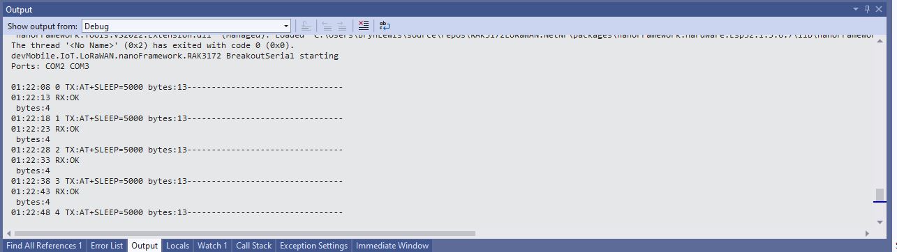
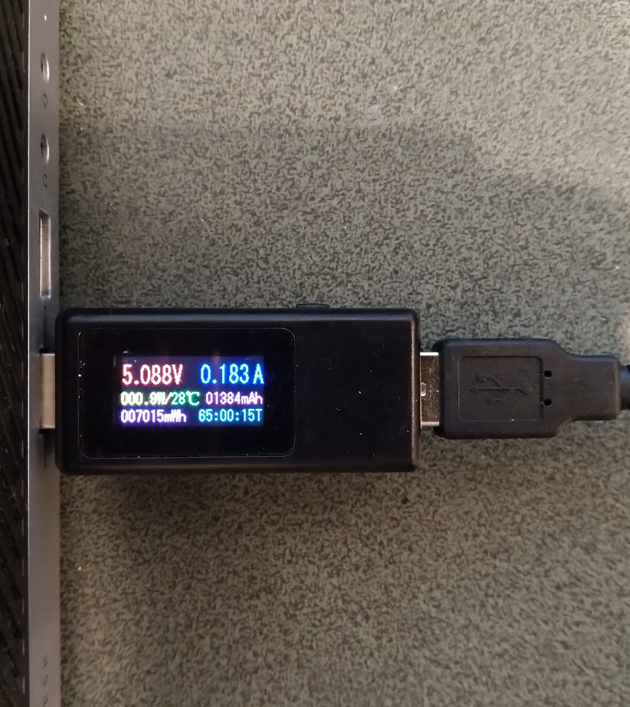
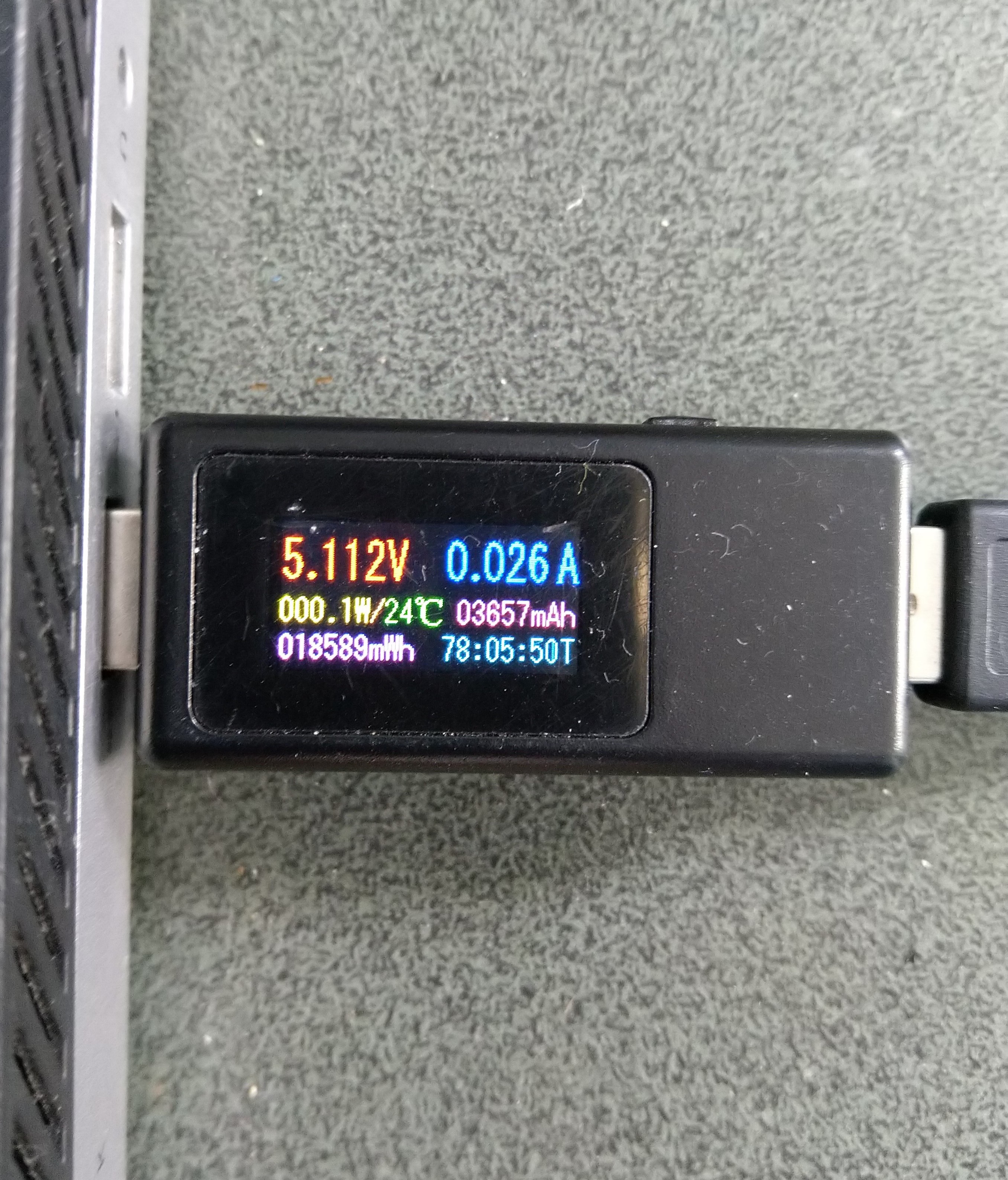
Initially the Sleep method didn’t appear to work, the power consumption didn’t change….
private static void SendMessageTimerCallback(object state)
{
	Rak3172LoRaWanDevice device = (Rak3172LoRaWanDevice)state;

#if PAYLOAD_HEX
	Debug.WriteLine($"{DateTime.UtcNow:hh:mm:ss} port:{MessagePort} payload HEX:{PayloadHex}");
	Result result = device.Send(MessagePort, PayloadHex, SendTimeout);
#endif
#if PAYLOAD_BYTES
	Debug.WriteLine($"{DateTime.UtcNow:hh:mm:ss} port:{MessagePort} payload bytes:{Rak3172LoRaWanDevice.BytesToHex(PayloadBytes)}");
	Result result = device.Send(MessagePort, PayloadBytes, SendTimeout);
#endif
	if (result != Result.Success)
	{
		Debug.WriteLine($"Send failed {result}");
	}

#if SLEEP
	Thread.Sleep(7500); //10000 Works 5000 to short

	Debug.WriteLine($"{DateTime.UtcNow:hh:mm:ss} Sleep period:{SleepPeriod:hh:mm:ss}");
	result = device.Sleep(SleepPeriod);
	if (result != Result.Success)
	{
		Debug.WriteLine($"Sleep failed {result}");
		return;
	}
#endif
}
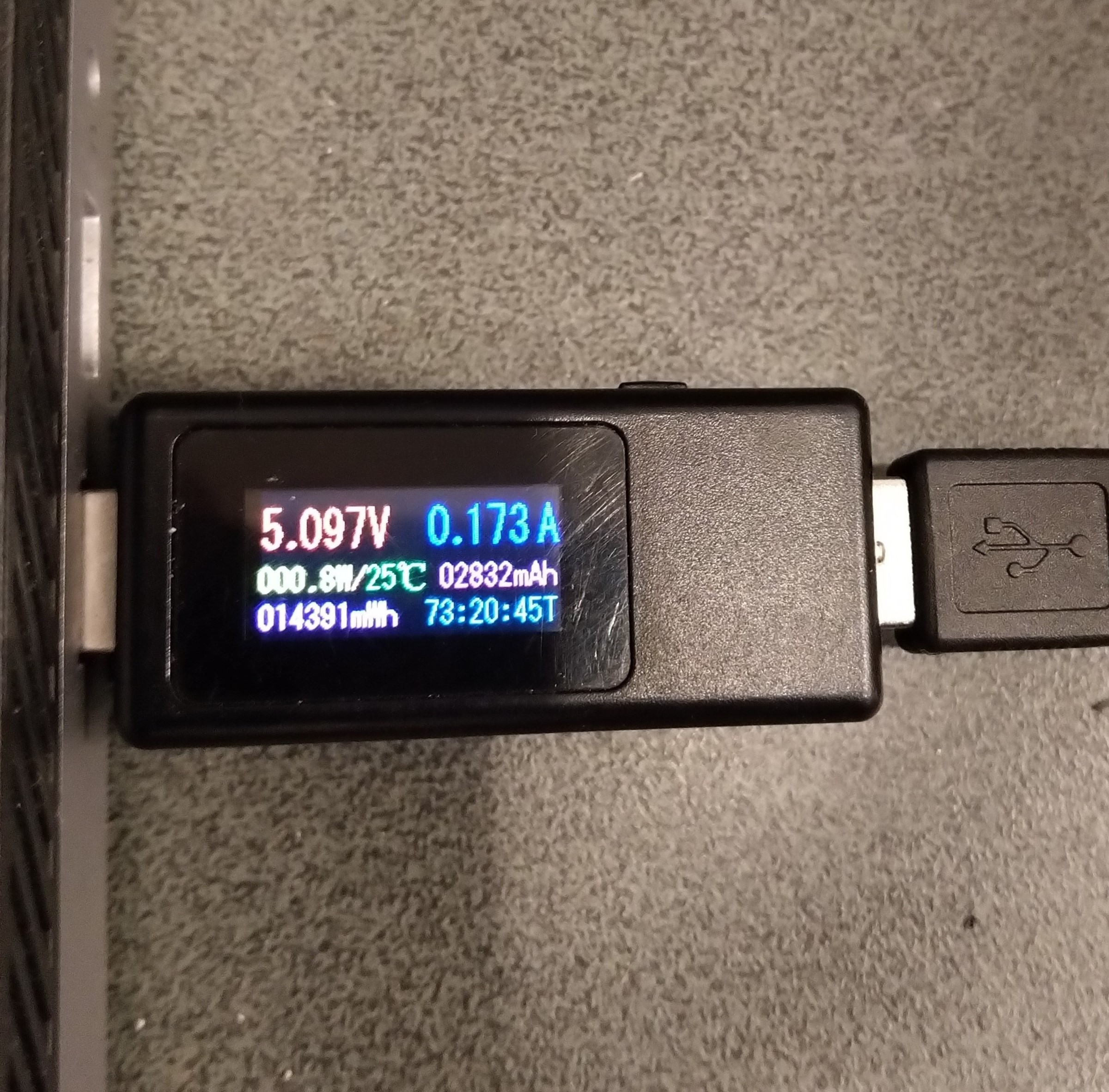
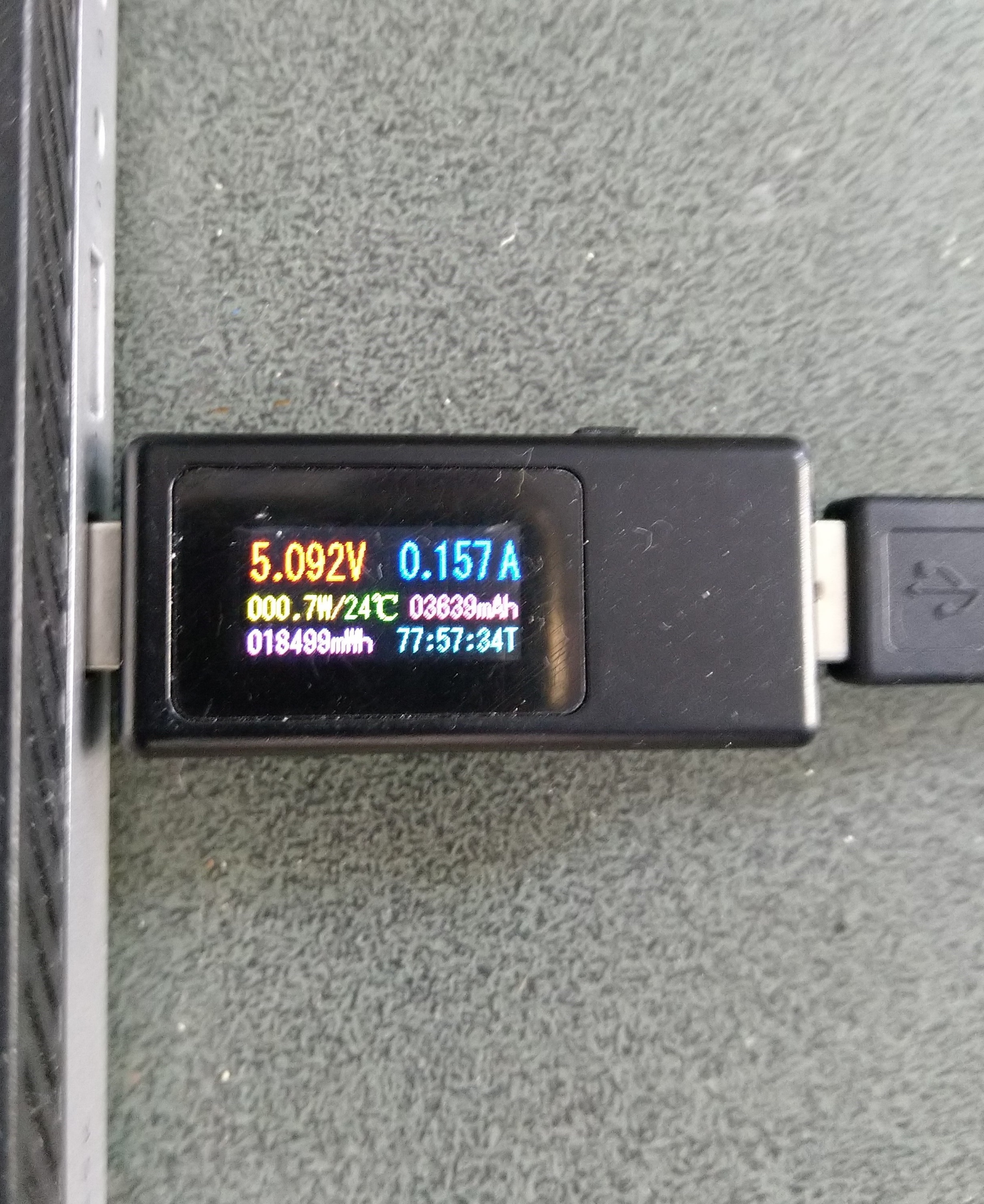
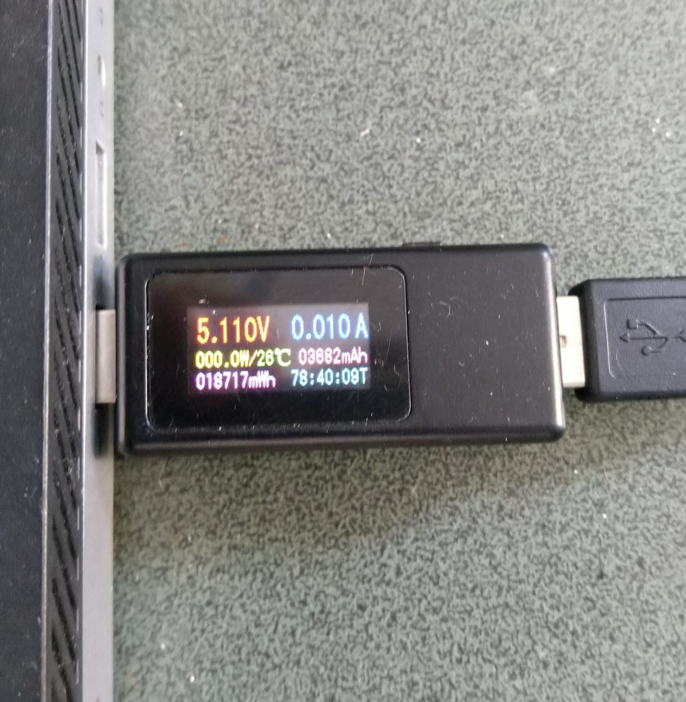
After some debugging and reading this helpful RAK Wireless forum post I added a short delay before sleeping the RAK3172 module and power consumption reduced.
Initially the Sleep method timed out every time it was called. After some more debugging I figured out that I needed a slightly longer delay for the AutoResetEvent.Waitone as it was timing out just before the “OK” was processed.
public Result Sleep(TimeSpan period)
{
	return Sleep(period, SleepExtensionDefault);
}

public Result Sleep(TimeSpan period, TimeSpan extension)
{
#if DIAGNOSTICS
	Debug.WriteLine($" {DateTime.UtcNow:hh:mm:ss} AT+SLEEP {period.TotalMilliseconds:f0} mSec");
#endif
	Result result = SendCommand("OK", $"AT+SLEEP={period.TotalMilliseconds:f0}", period.Add(extension));
	if (result != Result.Success)
	{
#if DIAGNOSTICS
		Debug.WriteLine($" {DateTime.UtcNow:hh:mm:ss} AT+SLEEP failed {result}");
#endif
		return result;
	}

	return Result.Success;
}