EV Telemetry Demo

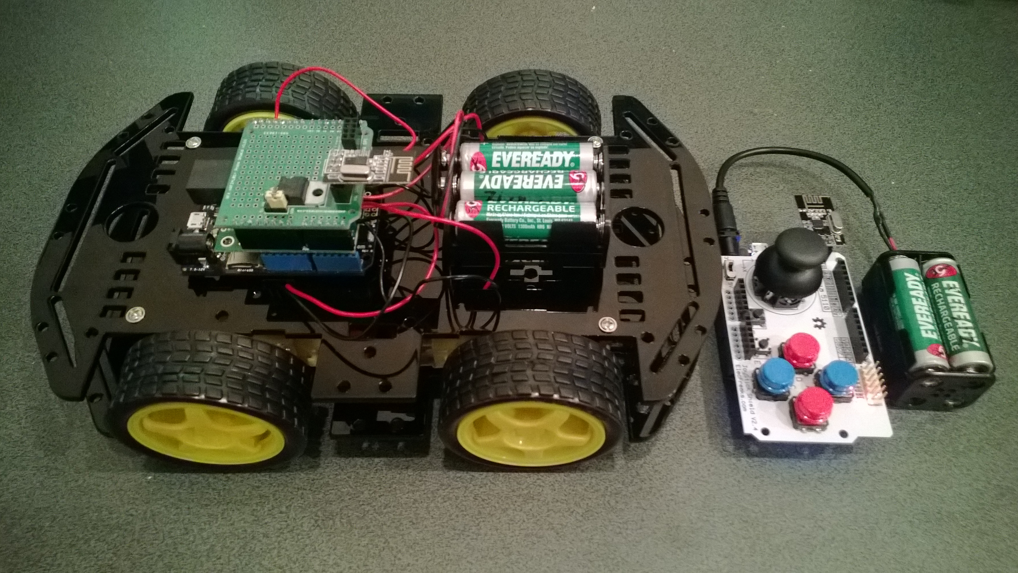
At EV Camp in June 2014 I talked about real-time telemetry for the electric carts. This is a demo of how this could be done using a couple of Netduinos, nRF24L01 modules and some other hardware

Telemetry Demo

Accelerometer and Throttle Position Telemetry

Bill of materials (Prices as at July 2014)

  • 2 x Netduino Plus 2 USD60,NZD108 or Netduino 2 USD33,NZD60
  • 2 x Embedded Coolness nRF24L01shields V1.1b + high power modules AUD17.85
  • 2 x Grove Base Shields V2 USD8.90
  • 1 x Grove ADX345 Accelerometer USD9.90
  • 1 x Grove Rotary Angle Sensor USD2.90
  • 1 x Grove 16×2 LCD USD13.90 (Using earlier serial display in pictures)

The mobile device configures the Gralin nRF24L01 library, initialises the Love Electronics ADXL345 Accelerometer library, and creates two timers, one for the throttle position the other for the accelerometer.

_module.OnTransmitFailed += OnSendFailure;
_module.OnTransmitSuccess += OnSendSuccess;
_module.Initialize(SPI.SPI_module.SPI1, Pins.GPIO_PIN_D7, Pins.GPIO_PIN_D3, Pins.GPIO_PIN_D2);
_module.Configure(myAddress, channel);
_module.Enable();

accel.EnsureConnected();
accel.Range = 2;
accel.FullResolution = true;
accel.EnableMeasurements();
accel.SetDataRate(0x0F);

Timer throttlePositionUpdates = new Timer(throttleTimerProc, null, 500, 500);
Timer accelerometerUpdates = new Timer(AccelerometerTimerProc, null, 500, 500);

Thread.Sleep( Timeout.Infinite ) ;

The Accelerometer timer reads the x, y & z accelerations then sends the data as an ASCII string (rather than Unicode) to save space (maximum message length is 32 bytes)

private void AccelerometerTimerProc(object state)
{
accel.ReadAllAxis();
Debug.Print("A- X = " + accel.ScaledXAxisG.ToString("F2") + " Y = " + accel.ScaledYAxisG.ToString("F2") + " Z = " + accel.ScaledZAxisG.ToString("F2"));

_module.SendTo(baseStationAddress, Encoding.UTF8.GetBytes("A " + accel.ScaledXAxisG.ToString("F1") + " " + accel.ScaledYAxisG.ToString("F1") + " " + accel.ScaledZAxisG.ToString("F1")));
}

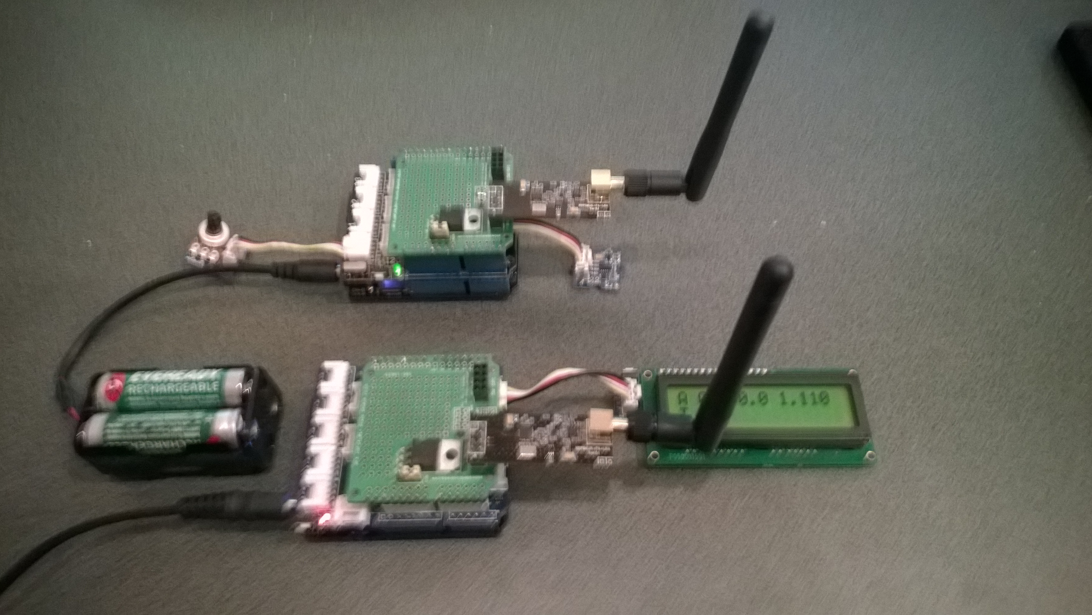
The base station works in a similar way, configuring the nRF24L01 library then displaying the received messages on the LCD Display.

Remote control 4WD robot build part2

I finally had some time to finish off the 4WD robot I first blogged about in February this year.

robot and remote control

Netduino 4wd robot and remote control unit

When I fired up the robot the nrf24L01 module on the embedded coolness shield was having some problems with electrical noise from the motors. This noise was causing the wireless module to report errors then stop working. So, based on this article by Pololu I added some noise suppression capacitors. There are two 0.1uF capacitors per motor and they connect the power supply pins to the metal casing of the motor. I have also twisted the motor supply wires and added some capacitors to the motor shield.

Motors with noise suppression capacitors

Netduino 4WD Robot motors with noise suppression capacitors

The Elecfreaks Joystick has to be modified to work with a Netduino. The remote control uses the initial position of the joystick for a calibration offset then sends 4 byte commands to the robot every 250mSec. The first two bytes are the motor directions and the last two are the motor speeds.

_module.OnDataReceived += OnReceive;
_module.OnTransmitFailed += OnSendFailure;
_module.OnTransmitSuccess += OnSendSuccess;

_module.Initialize(SPI.SPI_module.SPI1, Pins.GPIO_PIN_D10, Pins.GPIO_PIN_D9, Pins.GPIO_PIN_D1);
_module.Configure(_ControllerAddress, channel);
_module.Enable();

xOffset = xAxis.Read();
yOffset = yAxis.Read();

_timer = new Timer(SendMessage, null, 250, 250);
Thread.Sleep(Timeout.Infinite);

Then

byte[] command = { motor1Direction, motor2Direction, motor1Speed, motor2Speed };
_module.SendTo(_RobotAddress, command);

After trialling the robot round the house I added a timer to shut the motors down if connectivity was lost. Before adding the noise suppression capacitors I managed to plough the robot into the wall when the radio link failed and the motors were running at close to full speed.

Timer CommunicationsMonitorTimer = newTimer(CommunicationsMonitorTimerProc, null, 500, 500);
void CommunicationsMonitorTimerProc(object status)
{
   if (( DateTime.UtcNow - _MessageLastReceivedAt ) > MessageMaximumInterval)
   {
      Debug.Print("Communications timeout");
      M1Speed.DutyCycle = 0.0;
      M2Speed.DutyCycle = 0.0;
   }
}

Electric Vehicle Camp 2014-06

The Hardware

The software

Flash an LED

OutputPort led = new OutputPort(Pins.ONBOARD_LED, false);
while ( true)
{
   Led.Write(!Led.Read())
   Thread.Sleep(500)
}

Digital Input – Polled

InputPort button = new InputPort(Pins.ONBOARD_SW1, false, Port.ResistorMode.Disabled);
OutputPort led = new OutputPort(Pins.ONBOARD_LED, false);
while (true)
{
   led.Write(button.Read());
   Thread.Sleep(1000);
}

Digital Input – Interrupt

static OutputPort interuptled = new OutputPort(Pins.ONBOARD_LED, false);
InterruptPort button = new InterruptPort(Pins.ONBOARD_SW1, false, Port.ResistorMode.Disabled, Port.InterruptMode.InterruptEdgeHigh);
button.OnInterrupt += new NativeEventHandler(button_OnInterrupt);</span></code>

Thread.Sleep(Timeout.Infinite);
static void button_OnInterrupt(uint data1, uint data2, DateTime time)
{
   interuptled.Write(!interuptled.Read());
}

Analog Input

AnalogInput Sensor = new AnalogInput(Cpu.AnalogChannel.ANALOG_0);
while ( true)
{
   Debug.Print( "Value " + Sensor.Read("F2"));
   Thread.Sleep(500)
}

Pulse Width Modulation Output

AnalogInput brightness = new AnalogInput(AnalogChannels.ANALOG_PIN_A0);
PWM led = new PWM(PWMChannels.PWM_PIN_D5, 1000, 0.0, false);

led.Start();

while (true)
{
   Debug.Print("Brightness " + led.DutyCycle.ToString("F2"));
   led.DutyCycle = brightness.Read();
   Thread.Sleep(500);
}
led.Stop();

Telemetry – Mobile station

Configure the NRF24L01 library for the  elecfreaks Joystick ShieldV2.4, for more detail see this post 

_module.OnDataReceived += OnReceive;
_module.OnTransmitFailed += OnSendFailure;
_module.OnTransmitSuccess += OnSendSuccess;
_module.Initialize(SPI.SPI_module.SPI1, Pins.GPIO_PIN_D10, Pins.GPIO_PIN_D9, Pins.GPIO_PIN_D1);
_module.Configure(myAddress, channel);
_module.Enable();

Timer joystickPositionUpdates = new Timer(JoyStickTimerProc, null, 500, 500);
Thread.Sleep( Timeout.Infinite ) ;

Send the data to the base station (converting it from Unicode to ASCII)

private void JoyStickTimerProc(object state)
{
   double xVal = x.Read();
   double yVal = y.Read();
   Debug.Print("X " + xVal.ToString("F1") + " Y &" + yVal.ToString("F1"));

   _module.SendTo(baseStationAddress, Encoding.UTF8.GetBytes( xVal.ToString("F1") + " " + yVal.ToString("F1")));
}

Telemetry – Base Station

Configure the NRF24L01 library for the Embedded Coolness board, for more detail see this post

private readonly NRF24L01Plus _module;

_module.OnDataReceived += OnReceive;
_module.OnTransmitFailed += OnSendFailure;
_module.OnTransmitSuccess += OnSendSuccess;

_module.Initialize(SPI.SPI_module.SPI1, Pins.GPIO_PIN_D7, Pins.GPIO_PIN_D3, Pins.GPIO_PIN_D2);
_module.Configure(_myAddress, channel);
_module.Enable();

Display the inbound message (converting it from ASCII to Unicode)

private void OnReceive(byte[] data)
{
string message = new String(Encoding.UTF8.GetChars(data));
Debug.Print("Receive " + message); ;
}

Canterbury Software Cluster Internet of Things Presentation

For my presentation last week I prepared a sample xively and Netduino based application to illustrate what could be built with off the shelf kit. I built a wireless home monitoring system which had two energy consumption monitoring devices and a dual temperature sensor device. These devices uploaded their data using MQTT to xively in close to real time. Prices as at May 2014

The devices connected to the internet via a gateway.

Image

The software running on the Netduino was built using the NetMF library from KittyHawkMQ and the nRF24L01+ library from codeplex

Testing the solar powered temperature sensor monitoring my kitchen fridge. The fridge was 4° and the freezer was -18°

Image

The software was based on the nRF24L01library on codeplex,  Brad’s One-Wire and DS18B20 library with fixes from here.

Testing the power consumption monitor devices, with my “modified” power lead.

Image

The software was based on the approach in the Arduino code of the emon libraries from the Open Energy Monitor project which I’ll discuss in more detail in a future post.

Remote control 4WD robot build part1

A couple of parcels of parts arrived last week and I have started assembling my next robot project (possibly for code club). It’s a 4WD drive robot with an nRF24L01+ based remote control.

Robot chassis

ElecFreaks 4WD Robot and Remote

Had a slight problem with pin usage, the Embedded Coolness nRF24L01 shield and Pololu Dual MC33926 Motor Shield both use pin D2(irq) & D7(csn). The polulu shield supports some customising of pins so I disconnected D2(Status flag indicator), cut the D7 link (Motor 1 direction input) and wired it to pin D5.

modified motor shield

Pololu Dual MC33926 Modifications

I’m using the nRF24l01 driver from codeplex as basis for both ends of my remote control, code to follow…

Bill of materials (Prices USD as at Feb 2014)