Nasty OTAA connect
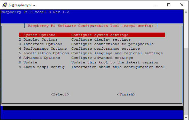
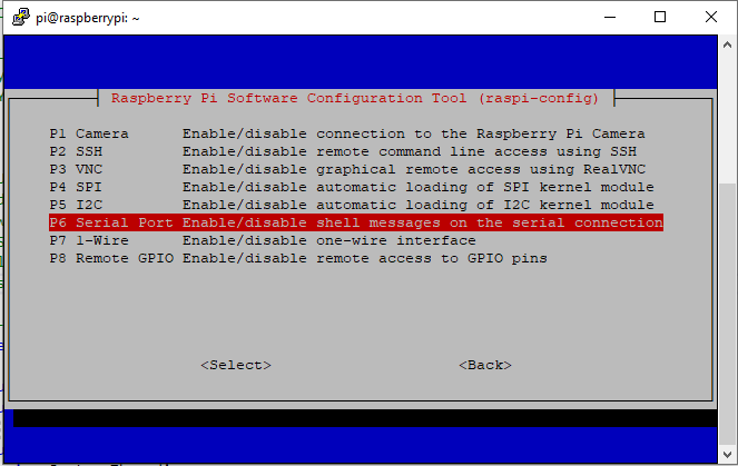
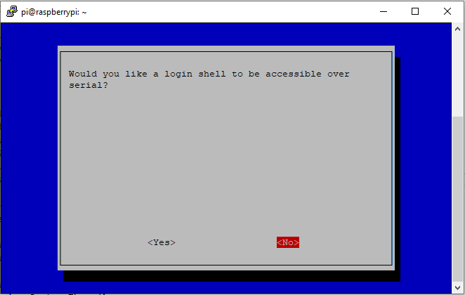
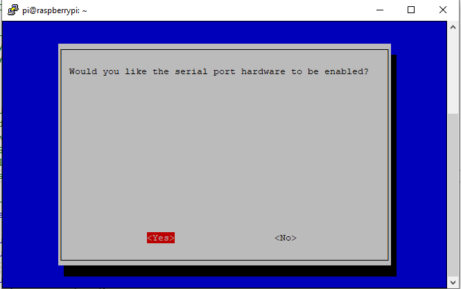
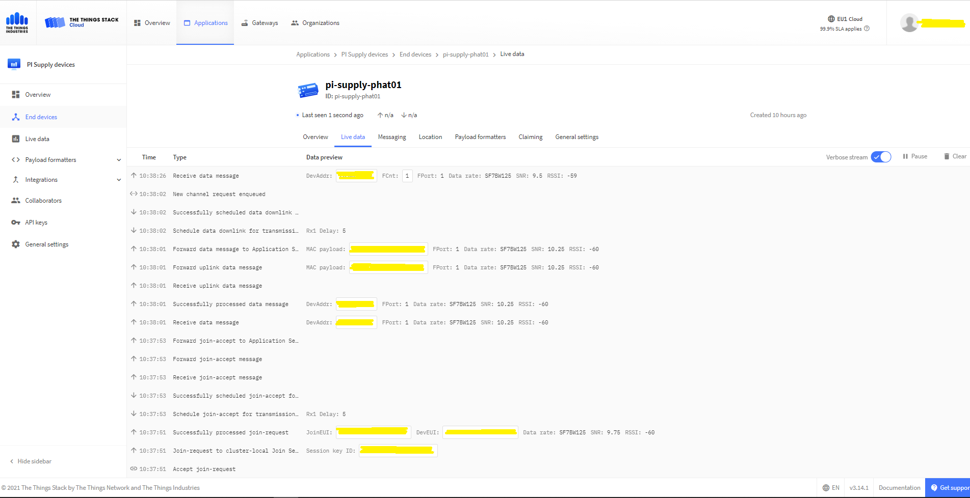
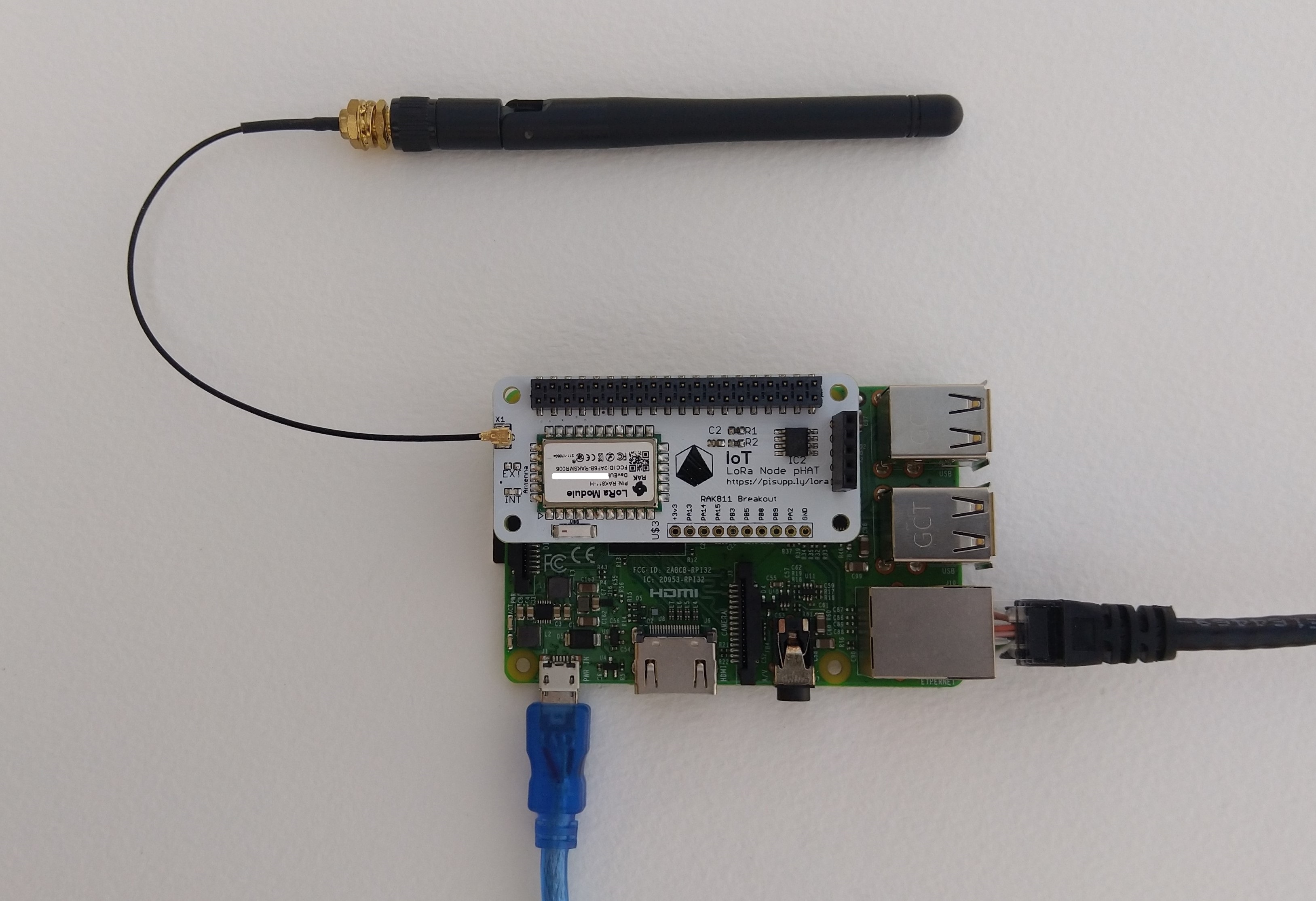
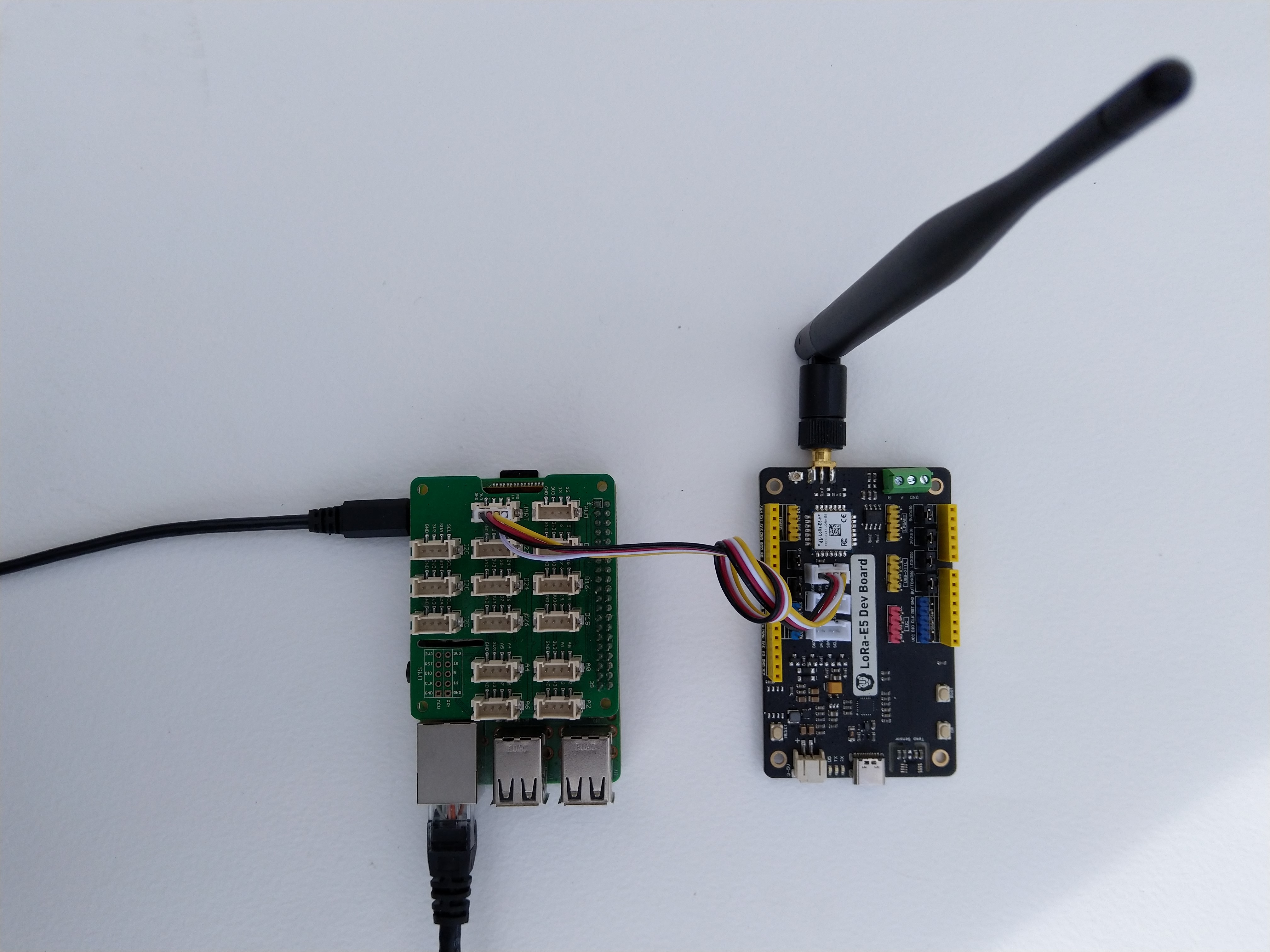
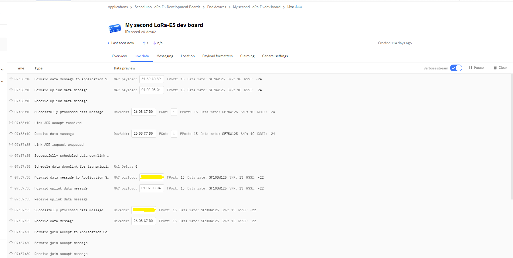
After getting basic connectivity for my Seeed LoRa-E5 test rig sorted I used RAK7246G LPWAN Developer Gateway on my bookcase to connect to The Things Network(TTN)
My Over the Air Activation (OTAA) implementation is very “nasty” I have assumed that there would be no timeouts or failures and I only send one BCD message “48656c6c6f204c6f526157414e” which is “hello LoRaWAN”.
The code just sequentially steps through the necessary configuration to join the TTN network with a suitable delay after each command is sent. There also appeared to be quite a variation in response times, especially for joining the network(most probably network related) and the progress of sending a message.
//---------------------------------------------------------------------------------
// Copyright (c) September 2021, devMobile Software
//
// Licensed under the Apache License, Version 2.0 (the "License");
// you may not use this file except in compliance with the License.
// You may obtain a copy of the License at
//
//     http://www.apache.org/licenses/LICENSE-2.0
//
// Unless required by applicable law or agreed to in writing, software
// distributed under the License is distributed on an "AS IS" BASIS,
// WITHOUT WARRANTIES OR CONDITIONS OF ANY KIND, either express or implied.
// See the License for the specific language governing permissions and
// limitations under the License.
//
//---------------------------------------------------------------------------------
namespace devMobile.IoT.NetCore.SeeedLoRaE5.NetworkJoinOTAA
{
	using System;
	using System.Diagnostics;
	using System.IO.Ports;
	using System.Threading;

	class Program
	{
		private const string SerialPortId = "/dev/ttyS0";

		private const string AppKey = "................................";
		private const string AppEui = "................";

		private const byte MessagePort = 15;

		//private const string Payload = "48656c6c6f204c6f526157414e"; // Hello LoRaWAN
		private const string Payload = "01020304"; // AQIDBA==
		//private const string Payload = "04030201"; // BAMCAQ==

		public static void Main()
		{
			string response;

			Debug.WriteLine("devMobile.IoT.SeeedLoRaE5.NetworkJoinOTAA starting");

			Debug.WriteLine(String.Join(",", SerialPort.GetPortNames()));

			try
			{
				using (SerialPort serialDevice = new SerialPort(SerialPortId))
				{
					// set parameters
					serialDevice.BaudRate = 9600;
					serialDevice.Parity = Parity.None;
					serialDevice.StopBits = StopBits.One;
					serialDevice.Handshake = Handshake.None;
					serialDevice.DataBits = 8;

					serialDevice.ReadTimeout = 10000;

					serialDevice.NewLine = "\r\n";

					serialDevice.Open();

					// clear out the RX buffer
					serialDevice.ReadExisting();
					response = serialDevice.ReadExisting();
					Debug.WriteLine($"Response :{response.Trim()} bytes:{response.Length}");
					Thread.Sleep(500);

					// Set the Region to AS923
					serialDevice.WriteLine("AT+DR=AS923\r\n");
					response = serialDevice.ReadLine();
					Debug.WriteLine($"Response :{response.Trim()} bytes:{response.Length}");

					// Set the Join mode
					serialDevice.WriteLine("AT +MODE=LWOTAA\r\n");
					response = serialDevice.ReadLine();
					Debug.WriteLine($"Response :{response.Trim()} bytes:{response.Length}");

					// Set the appEUI
					serialDevice.WriteLine($"AT+ID=AppEui,\"{AppEui}\"\r\n");
					response = serialDevice.ReadLine();
					Debug.WriteLine($"Response :{response.Trim()} bytes:{response.Length}");

					// Set the appKey
					serialDevice.WriteLine($"AT+KEY=APPKEY,{AppKey}\r\n");
					response = serialDevice.ReadLine();
					Debug.WriteLine($"Response :{response.Trim()} bytes:{response.Length}");

					// Set the port number
					serialDevice.WriteLine($"AT+PORT={MessagePort}\r\n");
					response = serialDevice.ReadLine();
					Debug.WriteLine($"Response :{response.Trim()} bytes:{response.Length}");

					// Join the network
					serialDevice.WriteLine("AT+JOIN\r\n");

					// Join start
					response = serialDevice.ReadLine();
					Debug.WriteLine($"Response :{response.Trim()} bytes:{response.Length}");

					// JOIN normal
					response = serialDevice.ReadLine();
					Debug.WriteLine($"Response :{response.Trim()} bytes:{response.Length}");

					Thread.Sleep(5000);

					// network joined
					response = serialDevice.ReadLine();
					Debug.WriteLine($"Response :{response.Trim()} bytes:{response.Length}");

					// Net ID
					response = serialDevice.ReadLine();
					Debug.WriteLine($"Response :{response.Trim()} bytes:{response.Length}");

					// Join done
					response = serialDevice.ReadLine();
					Debug.WriteLine($"Response :{response.Trim()} bytes:{response.Length}");

					while (true)
					{
						Debug.WriteLine("Sending");

						serialDevice.WriteLine($"AT+MSGHEX=\"{Payload}\"\r\n");

						// Start
						response = serialDevice.ReadLine();
						Debug.WriteLine($"Response :{response.Trim()} bytes:{response.Length}");

						// Fpending
						response = serialDevice.ReadLine();
						Debug.WriteLine($"Response :{response.Trim()} bytes:{response.Length}");

						//Read metrics
						response = serialDevice.ReadLine();
						Debug.WriteLine($"Response :{response.Trim()} bytes:{response.Length}");

						//Done
						response = serialDevice.ReadLine();
						Debug.WriteLine($"Response :{response.Trim()} bytes:{response.Length}");

						Thread.Sleep(30000);
					}
				}
			}
			catch (Exception ex)
			{
				Debug.WriteLine(ex.Message);
			}
		}
	}
}
The code is not suitable for production but it confirmed my software and hardware configuration worked.
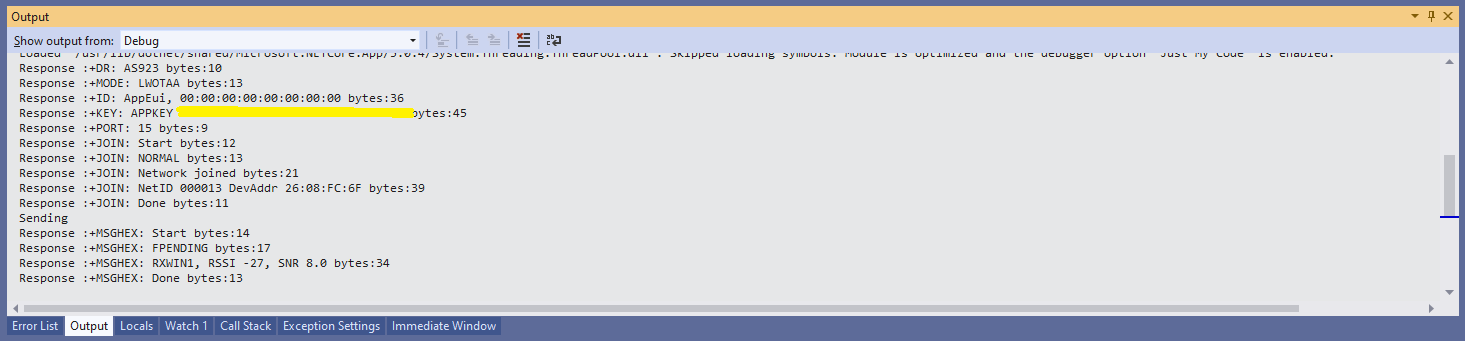
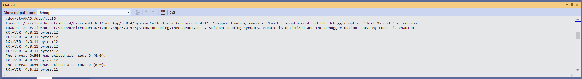
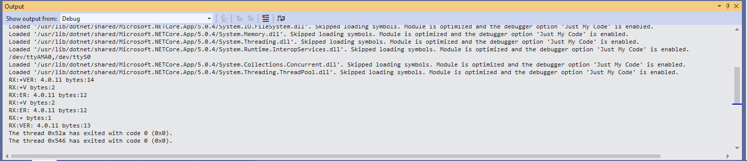
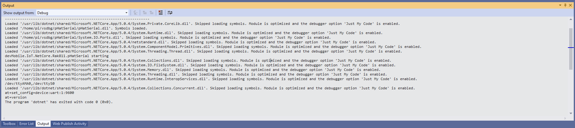
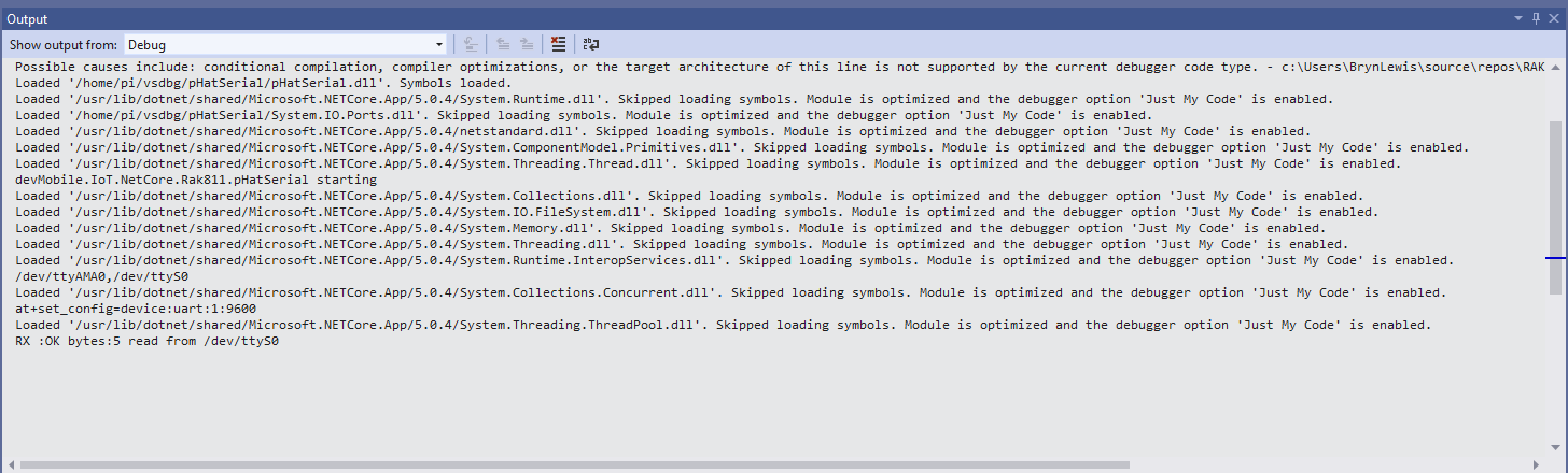
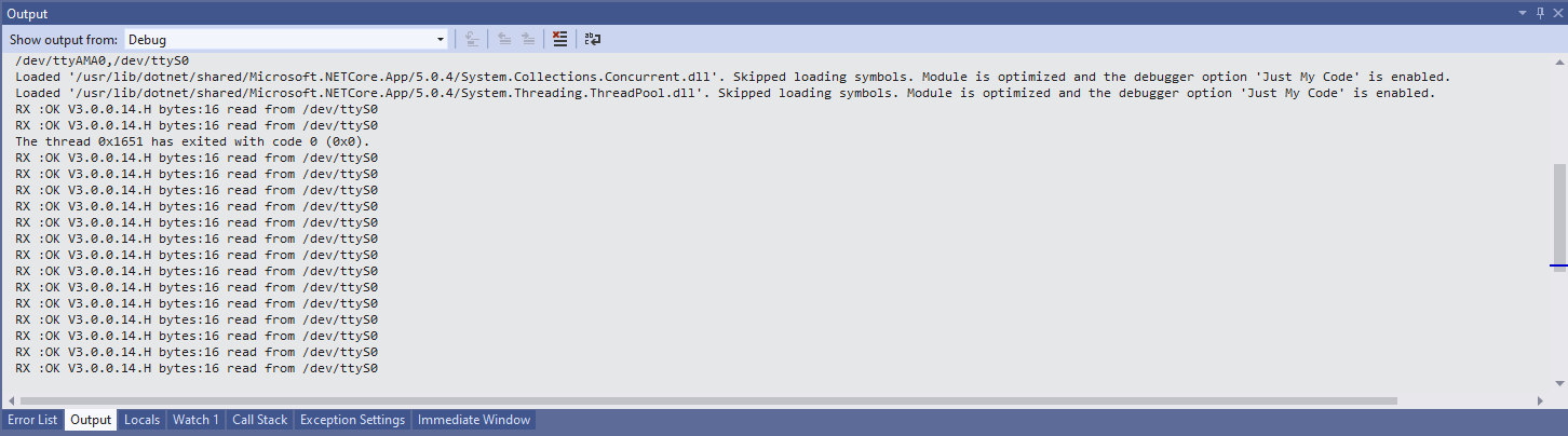
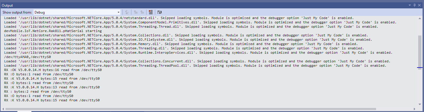
In the Visual Studio 2019 debug output I could see messages getting sent and then after a short delay they were visible in the TTN console.
Most of the LoRaWAN modems I have worked with reply “OK” when a command is successful. The SeeedLoRa-E5 often returns the payload of the request in the response which makes the code a little bit more complex.
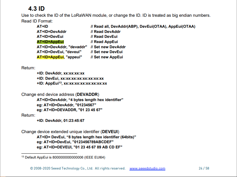
For example the AppEui can be passed in as “00:00:00:00:00:00:00:00” or “0000000000000000” but in the response the format is always “00:00:00:00:00:00:00:00”