Random wanderings through Microsoft Azure esp. PaaS plumbing, the IoT bits, AI on Micro controllers, AI on Edge Devices, .NET nanoFramework, .NET Core on *nix and ML.NET+ONNX
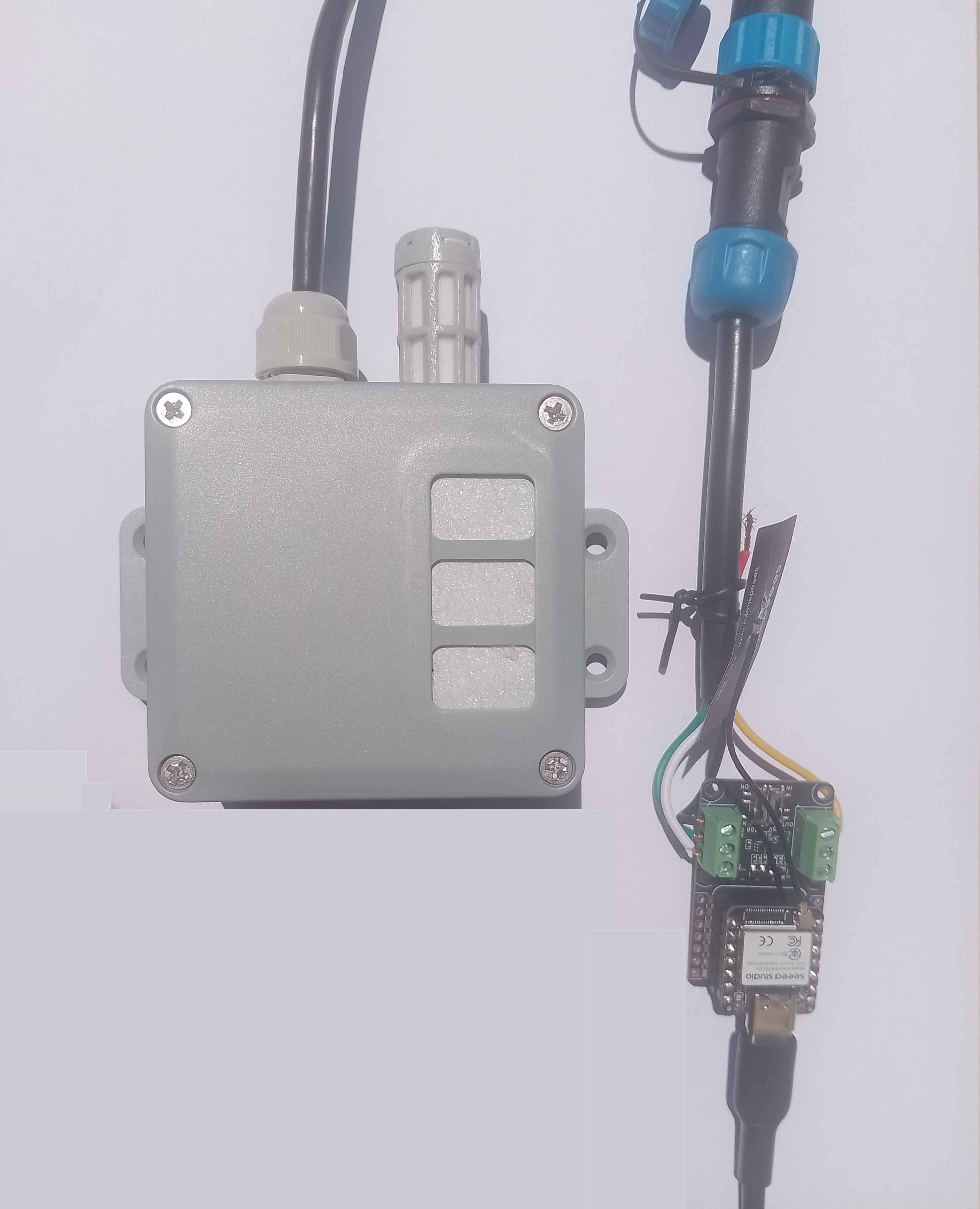
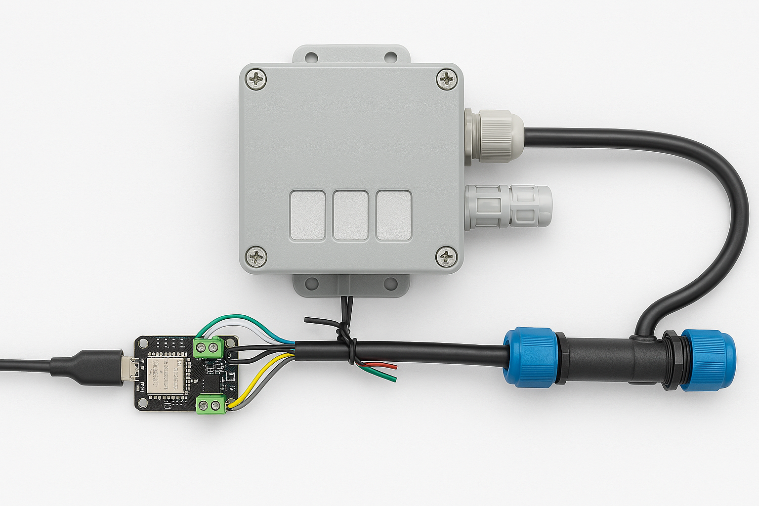
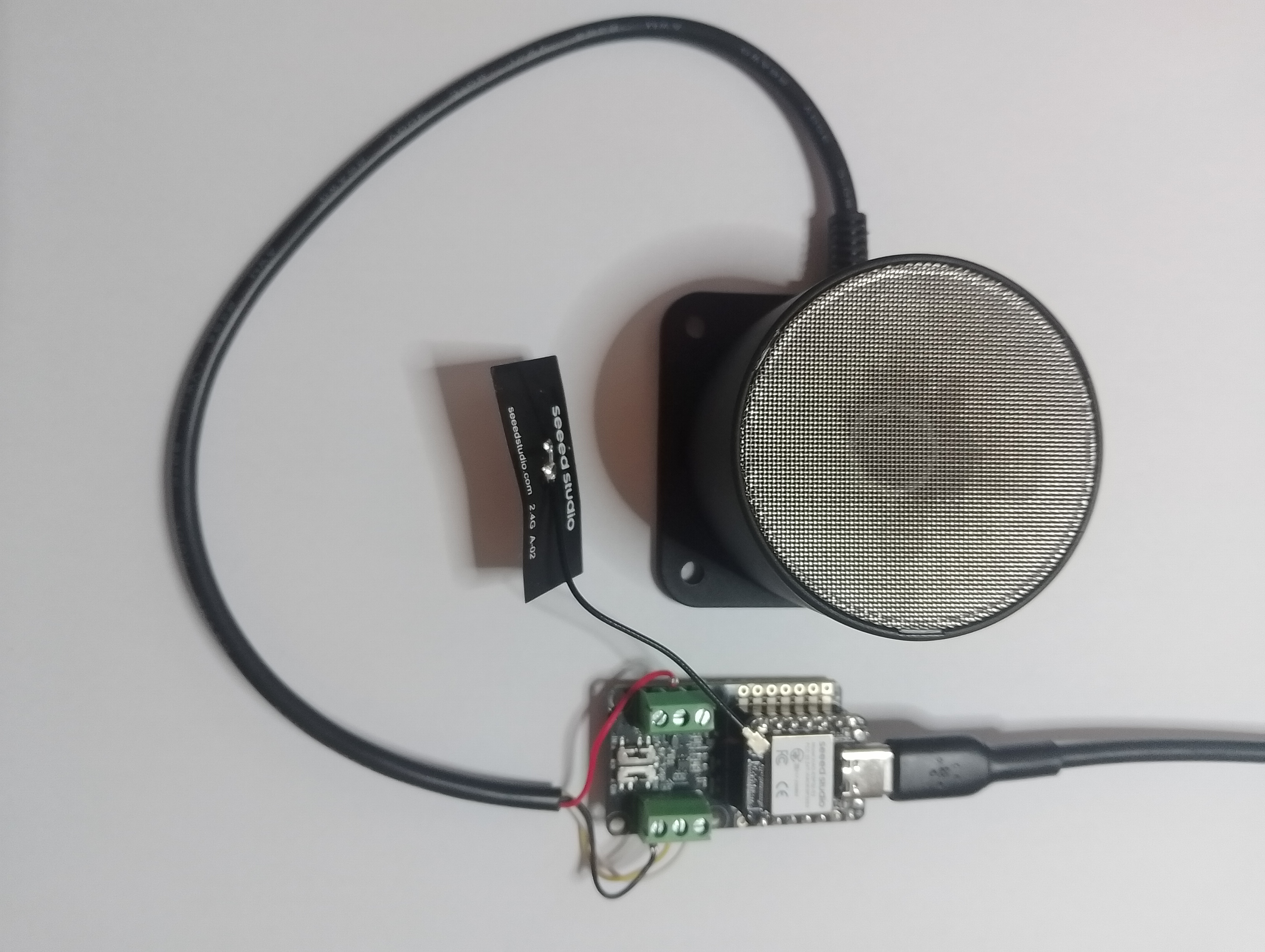
// XIAO ESP32S3 + RS485 breakout + Seeed 101991042 (RS-485 Modbus RTU)
// Reads: 0x0100 (calculated distance, mm), 0x0101 (real-time distance, mm),
// 0x0102 (temperature, 0.1°C). Can write 0x0200 (slave address).
// Serial: 9600 8N1 per datasheet. (Default slave addr = 0x01)
//Iot.Device.Modbus (namespace Iot.Device.Modbus.Client)
//using Iot.Device.Modbus;
using Iot.Device.Modbus.Client;
//using Microsoft.Extensions.Logging;
using nanoFramework.Hardware.Esp32;
//using nanoFramework.Logging.Debug;
using System;
using System.Diagnostics;
using System.IO.Ports;
using System.Threading;
namespace SeeedRS485500cmUltrasonicLevelSensor
{
public class Program
{
// === Sensor Modbus params (from Seeed datasheet) ===
private const byte SlaveAddress = 0x01; // default
private const ushort RegCalcDistance = 0x0100;// mm, ~500ms processing
//private const ushort RegRealDistance = 0x0101;// mm, ~100ms
private const ushort RegTemperature = 0x0102;// INT16, 0.1°C units
private const ushort RegSlaveAddress = 0x0200;// R/W address register
public static void Main()
{
ModbusClient _client;
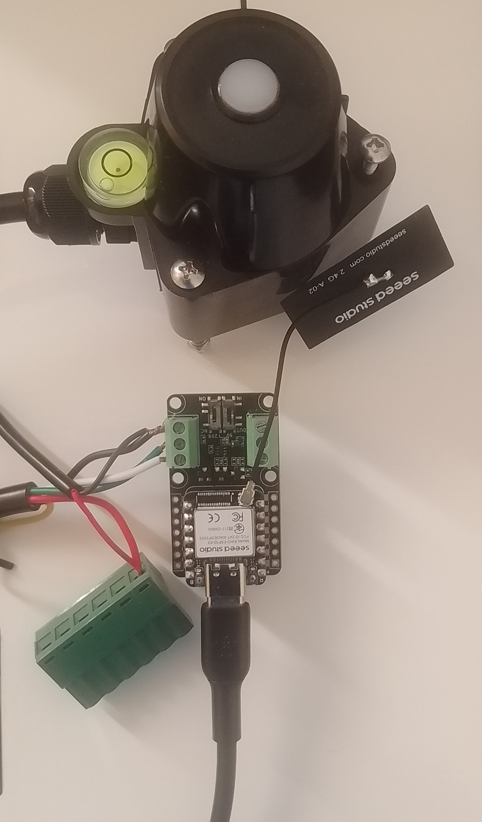
Console.WriteLine("Modbus: Seeed SKU101991042 Starting");
Configuration.SetPinFunction(Gpio.IO06, DeviceFunction.COM2_RX);
Configuration.SetPinFunction(Gpio.IO05, DeviceFunction.COM2_TX);
// This port number is a bit weird, need to double check in RS485 Sender/Receiver apps
Configuration.SetPinFunction(Gpio.IO03, DeviceFunction.COM2_RTS);
var ports = SerialPort.GetPortNames();
Debug.WriteLine("Available ports: ");
foreach (string port in ports)
{
Debug.WriteLine($" {port}");
}
using (_client = new ModbusClient("COM2"))
{
_client.ReadTimeout = _client.WriteTimeout = 2000;
//_client.Logger = new DebugLogger("ModbusClient")
//{
// MinLogLevel = LogLevel.Debug
//};
while (true)
{
try
{
// 0x0100 Calculated distance (mm). Takes ~500ms to compute per datasheet.
short[] calc = _client.ReadHoldingRegisters(SlaveAddress, RegCalcDistance, 1);
ushort calcMm = (ushort)calc[0];
float calcCm = calcMm / 10.0f;
Console.WriteLine($"Calculated distance: {calcMm} mm ({calcCm:F1} cm)");
/*
// 0x0101 Real-time distance (mm). Faster ~100ms response.
short[] real = _client.ReadHoldingRegisters(SlaveAddress, RegRealDistance, 1);
short realMm = real[0];
float realCm = realMm / 10.0f;
Console.WriteLine($"Real-time distance: {realMm} mm ({realCm:F1} cm)");
*/
// 0x0102 Temperature (INT16, 0.1°C)
short[] temp = _client.ReadHoldingRegisters(SlaveAddress, RegTemperature, 1);
short tempRaw = unchecked((short)temp[0]); // signed per datasheet
float tempC = tempRaw / 10.0f;
Console.WriteLine($"Temperature: {tempC:F1} °C");
}
catch (Exception ex)
{
Console.WriteLine($"Modbus read failed: {ex.Message}");
}
Thread.Sleep(10000);
}
}
}
}
}
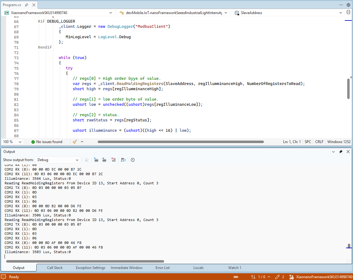
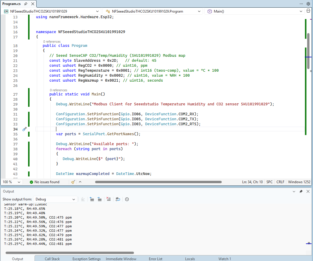
The nanoFramework logging support made debugging connectivity issues much faster. So much so I started with the nanoFramework application then progressed to the Arduino version.
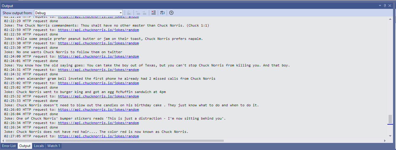
I had to add a short delay between each Modbus sensor value read to stop timeout errors.
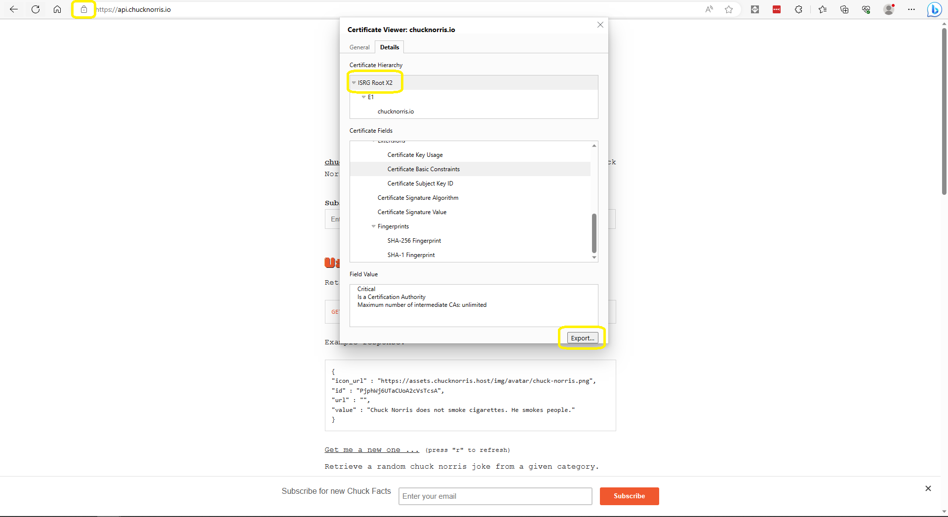
Some of the Chuck Norris facts are not suitable for school students so the request Uniform Resource Locator (URL) can be modified to ensure only “age appropriate” ones are returned.
The first step was to flash the WT32-SC01 with the latest version of the .NET nanoFramework for ESP32 devices. To get the device into “boot” mode I used a jumper wire to connect GPIO0 to ground before powering it up.
WT32-SC01 boot loader mode jumper
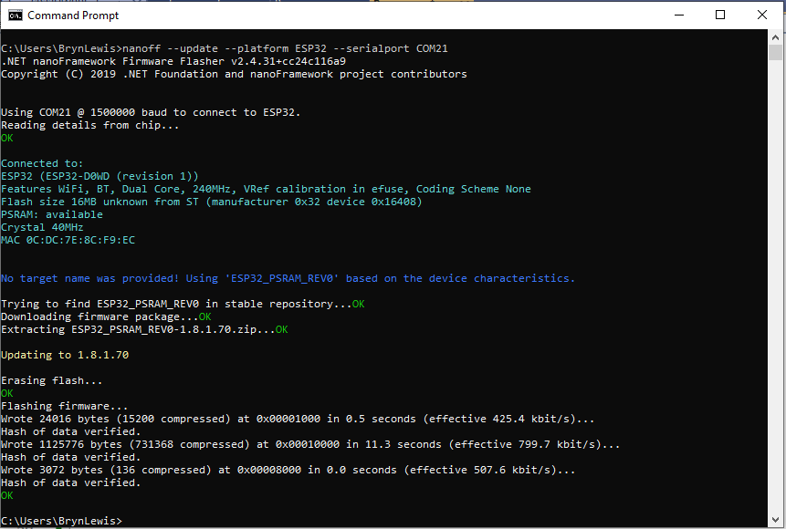
The .NET nanoFramework nanoff utility identified the device, downloaded the runtime package, and updated the device.
updating the WT32-SC01 with the nanoff utility
The next step was to run the blank NET nanoFramework sample application.
using System;
using System.Diagnostics;
using System.Threading;

namespace HelloWorld
{
    public class Program
    {
        public static void Main()
        {
            Debug.WriteLine("Hello from nanoFramework!");

            Thread.Sleep(Timeout.Infinite);

            // Browse our samples repository: https://github.com/nanoframework/samples
            // Check our documentation online: https://docs.nanoframework.net/
            // Join our lively Discord community: https://discord.gg/gCyBu8T
        }
    }
}
Microsoft Visual Studio 2022 displaying output of .NET nanoFramework Blank application
//
// Copyright (c) .NET Foundation and Contributors
// See LICENSE file in the project root for full license information.
//

using System.Device.Gpio;
using System;
using System.Threading;
using nanoFramework.Hardware.Esp32;

namespace Blinky
{
    public class Program
    {
        private static GpioController s_GpioController;
        public static void Main()
        {
            s_GpioController = new GpioController();

            // IO23 is LCD backlight
            GpioPin led = s_GpioController.OpenPin(Gpio.IO23,PinMode.Output );

            led.Write(PinValue.Low);

            while (true)
            {
                led.Toggle();
                Thread.Sleep(125);
                led.Toggle();
                Thread.Sleep(125);
                led.Toggle();
                Thread.Sleep(125);
                led.Toggle();
                Thread.Sleep(525);
            }
        }
    }
}
The
Flashing WT32-SC01 LCD backlight
Next steps getting the LCD+Touch panel and Wifi working
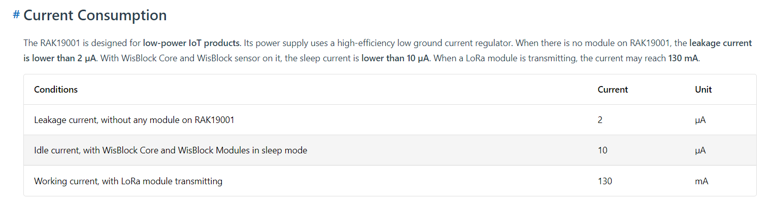
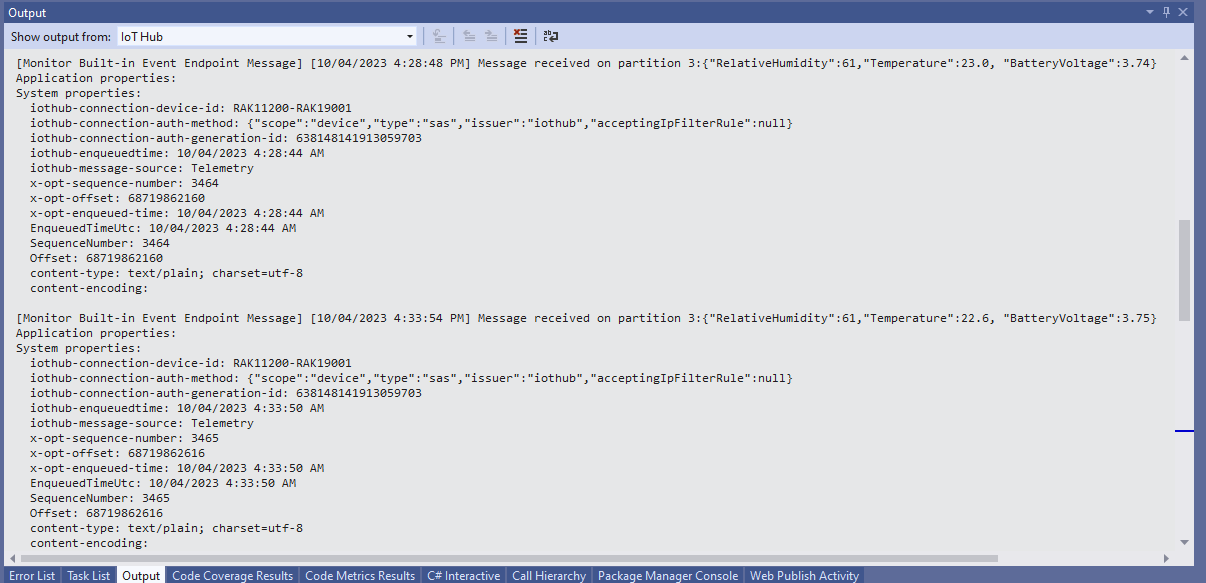
The voltage my test setup was calculating looked wrong, then I realised that the sample calculation in the RAK Wireless forums wasn’t applicable to my setup.
I updated the formula used to calculate the battery voltage and deployed the application
public static void Main()
{
Debug.WriteLine($"{DateTime.UtcNow:HH:mm:ss} devMobile.IoT.RAK.Wisblock.AzureIoTHub.RAK11200.PowerSleep starting");
Thread.Sleep(5000);
try
{
double batteryVoltage;
Configuration.SetPinFunction(Gpio.IO04, DeviceFunction.I2C1_DATA);
Configuration.SetPinFunction(Gpio.IO05, DeviceFunction.I2C1_CLOCK);
Debug.WriteLine($"{DateTime.UtcNow:HH:mm:ss} Battery voltage measurement");
// Configure Analog input (AIN0) port then read the "battery charge"
AdcController adcController = new AdcController();
using (AdcChannel batteryVoltageAdcChannel = adcController.OpenChannel(AdcControllerChannel))
{
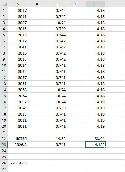
batteryVoltage = batteryVoltageAdcChannel.ReadValue() / 723.7685;
Debug.WriteLine($" BatteryVoltage {batteryVoltage:F2}");
if (batteryVoltage < Config.BatteryVoltageBrownOutThreshold)
{
Sleep.EnableWakeupByTimer(Config.FailureRetryInterval);
Sleep.StartDeepSleep();
}
}
catch (Exception ex)
{
...
}
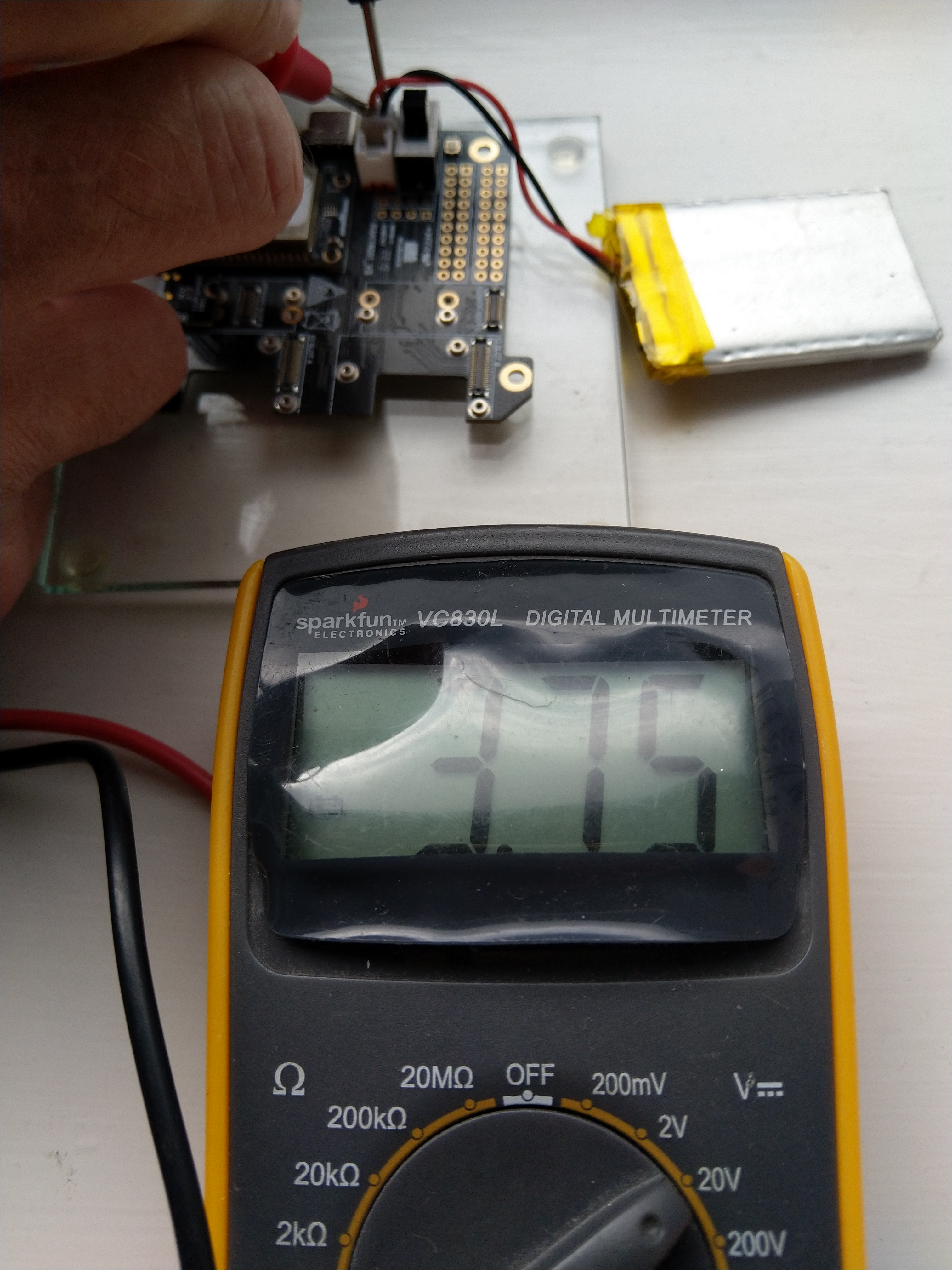
To test the accuracy of the voltage calculation I am going to run my setup on the office windowsill for a week regularly measuring the voltage. Then, turn the solar panel over (so the battery is not getting charged) and monitor the battery discharging until the RAK11200 WisBlock WiFi Module won’t connect to the network.
After some “tinkering” I found the voltage calculation was surprisingly accurate (usually within 0.01V) for my RAK19001 and RAK19007 base boards.
When the battery voltage was close to its minimum working voltage of the ESP32 device it would reboot when the WifiNetworkHelper.ConnectDhcp method was called. This would quickly drain the battery flat even when the solar panel was trying to charge the battery.
Now, before trying to connect to the wireless network the battery voltage is checked and if too low (more experimentation required) the device goes into a deep sleep for a configurable period (more experimentation required). This is so the solar panel can charge the battery to a level where wireless connectivity will work.
When developing libraries it’s good to have a selection of different platforms for testing as this can significantly improve the quality and robustness of the implementation. A few months ago I noticed that RAK Wireless have a UWB Module Decawave DW1000 Wisblock so I added one to an order.
I have added a couple of C# processor directives (MAKERFABS_ESP32UWB & RAK11200_RAK1907_RAK13801) so the platform that the Qorvo DW1000 module is running on can be configured.
public class Program
{
#if MAKERFABS_ESP32UWB
private const int SpiBusId = 1;
private const int chipSelectLine = Gpio.IO04;
#endif
#if RAK11200_RAK1907_RAK13801
private const int SpiBusId = 1;
private const int chipSelectLine = Gpio.IO32;
#endif
public static void Main()
{
Thread.Sleep(5000);
Debug.WriteLine("devMobile.IoT.Dw1000.ShieldSPI starting");
try
{
#if MAKERFABS_ESP32UWB
Configuration.SetPinFunction(Gpio.IO19, DeviceFunction.SPI1_MISO);
Configuration.SetPinFunction(Gpio.IO23, DeviceFunction.SPI1_MOSI);
Configuration.SetPinFunction(Gpio.IO18, DeviceFunction.SPI1_CLOCK);
#endif
#if RAK11200_RAK1907_RAK13801
Configuration.SetPinFunction(Gpio.IO35, DeviceFunction.SPI1_MISO);
Configuration.SetPinFunction(Gpio.IO25, DeviceFunction.SPI1_MOSI);
Configuration.SetPinFunction(Gpio.IO33, DeviceFunction.SPI1_CLOCK);
#endif
var settings = new SpiConnectionSettings(SpiBusId, chipSelectLine)
{
ClockFrequency = 2000000,
Mode = SpiMode.Mode0,
};
using (SpiDevice device = SpiDevice.Create(settings))
{
while (true)
{
byte[] writeBuffer = new byte[] { 0x0, 0x0, 0x0, 0x0, 0x0 }; // 0x0 = DEV_ID
byte[] readBuffer = new byte[writeBuffer.Length];
device.TransferFullDuplex(writeBuffer, readBuffer); // 15, 48, 1, 202, 222
uint ridTag = (uint)(readBuffer[4]<< 8 | readBuffer[3]);
byte model = readBuffer[2];
byte ver = (byte)(readBuffer[1] >> 4);
byte rev = (byte)(readBuffer[1] & 0x0f);
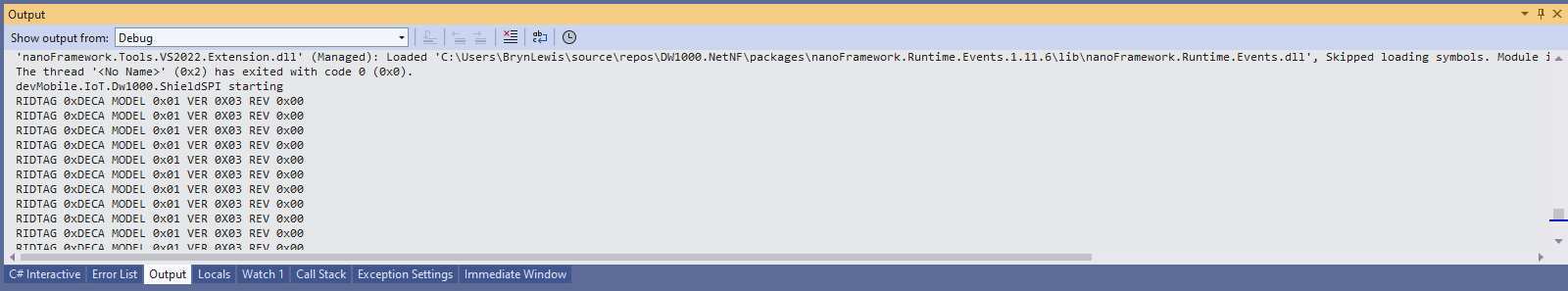
Debug.WriteLine(String.Format($"RIDTAG 0x{ridTag:X2} MODEL 0x{model:X2} VER 0X{ver:X2} REV 0x{rev:X2}"));
Thread.Sleep(10000);
}
}
}
catch (Exception ex)
{
Debug.WriteLine(ex.Message);
}
}
}
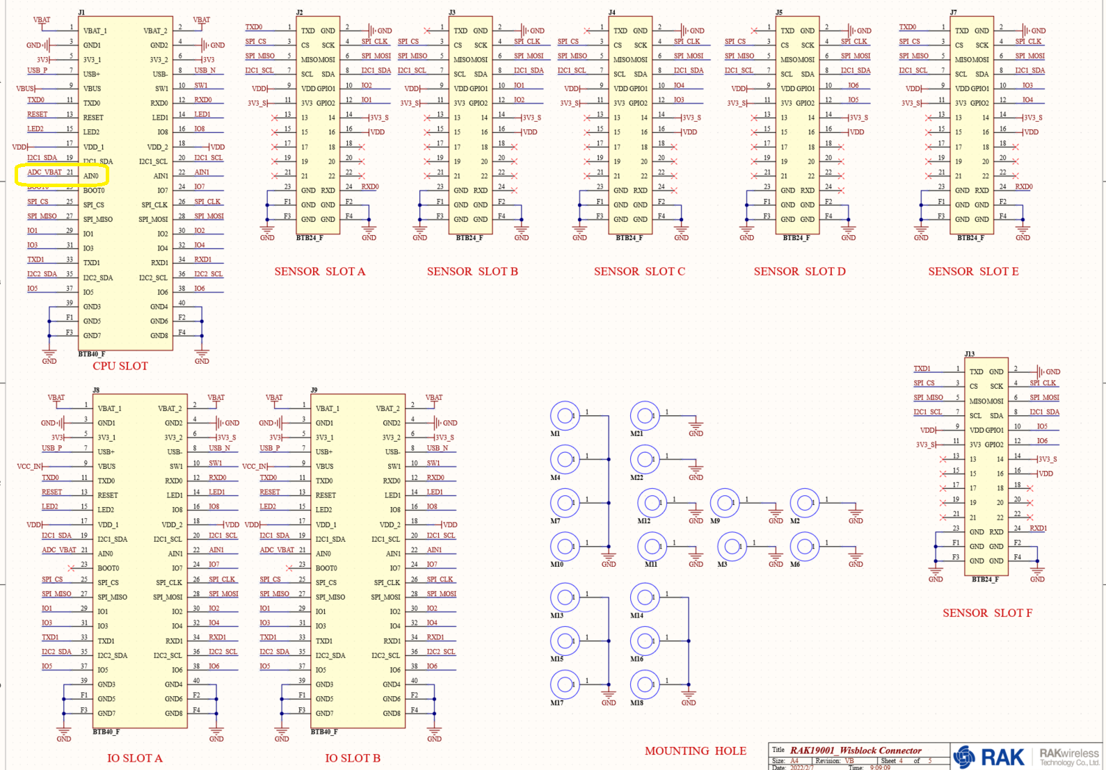
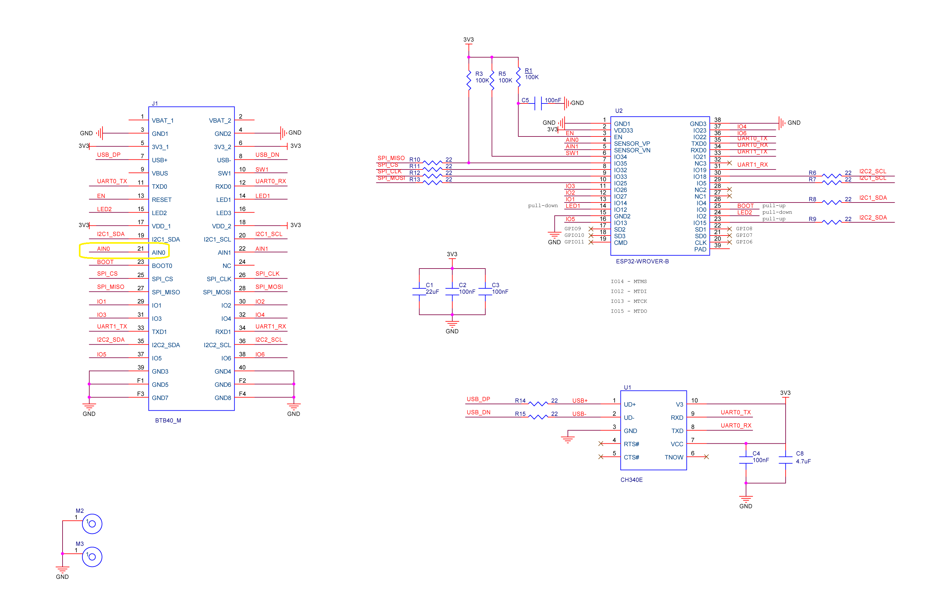
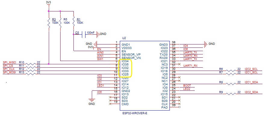
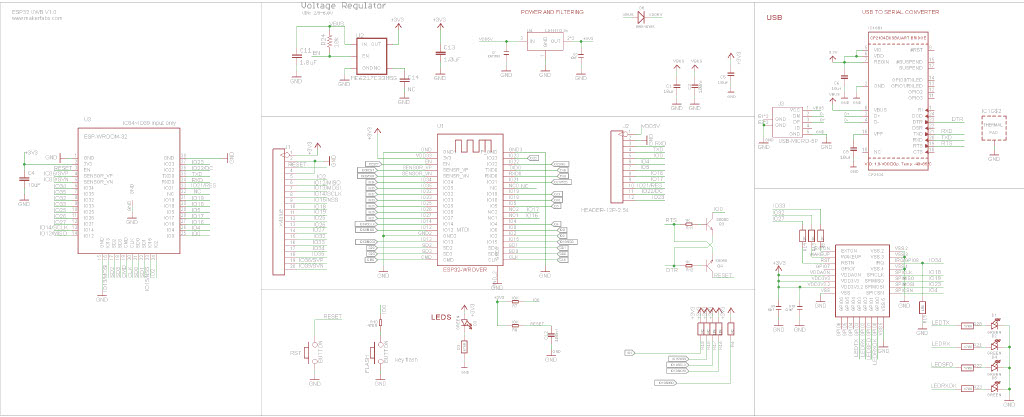
The alignment of the RAK11200 WisBiock Core Module pins and labels on the circuit diagram tripped me up. My initial configuration caused the device to reboot every time the application started.
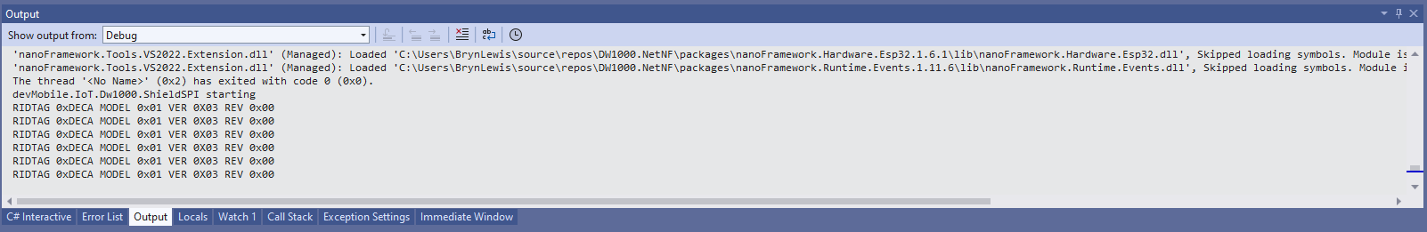
Visual Studio 2022 Debug window displaying the decoded value from Register 0x0
At the top of test applications, I usually have a brief delay i.e Thread.Sleep(5000) so I can attach the debugger or erase the flash before the application crashes.
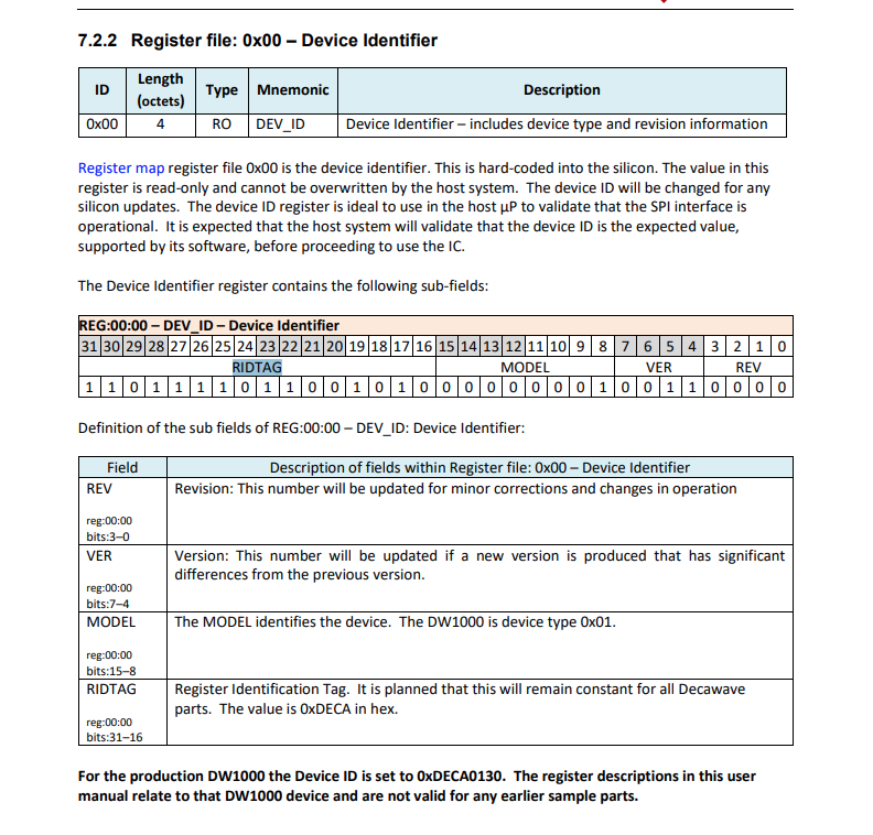
Even though SPI is an industry standard there are often subtle differences which need to be taken into account when reading from/writing to registers. The DW1000 has a static “Device Identifier” which I used to debug my “proof of concept” code.
DW1000 Datasheet Register Map documentation for Register 0x00
The DeviceSPI program reads register 0x00 and then displays the decoded payload.
public class Program
{
#if MAKERFABS_ESP32UWB
    private const int SpiBusId = 1;
    private const int chipSelectLine = Gpio.IO04;
#endif

    public static void Main()
    {
        Thread.Sleep(5000);

        Debug.WriteLine("devMobile.IoT.Dw1000.ShieldSPI starting");

        try
        {
#if MAKERFABS_ESP32UWB
            Configuration.SetPinFunction(Gpio.IO19, DeviceFunction.SPI1_MISO);
            Configuration.SetPinFunction(Gpio.IO23, DeviceFunction.SPI1_MOSI);
            Configuration.SetPinFunction(Gpio.IO18, DeviceFunction.SPI1_CLOCK);
#endif
            var settings = new SpiConnectionSettings(SpiBusId, chipSelectLine)
            {
                ClockFrequency = 2000000,
                Mode = SpiMode.Mode0,
            };

            using (SpiDevice device = SpiDevice.Create(settings))
            {
                Thread.Sleep(500);

                while (true)
                {
                    /*
                    byte[] writeBuffer = new byte[] { 0x0, 0x0, 0x0, 0x0, 0x0 }; // 0x0 = DEV_ID
                    byte[] readBuffer = new byte[writeBuffer.Length];

                    device.TransferFullDuplex(writeBuffer, readBuffer); // 15, 48, 1, 202, 222
                    */

                    byte[] writeBuffer = new byte[] { 0x0 }; // 0x0 = DEV_ID
                    byte[] readBuffer = new byte[5];

                    device.TransferFullDuplex(writeBuffer, readBuffer); // 15, 48, 1, 202, 222

                    uint ridTag = (uint)(readBuffer[4]<< 8 | readBuffer[3]);
                    byte model = readBuffer[2];
                    byte ver = (byte)(readBuffer[1] >> 4);
                    byte rev = (byte)(readBuffer[1] & 0x0f);

                    Debug.WriteLine(String.Format($"RIDTAG 0x{ridTag:X2} MODEL 0x{model:X2} VER 0X{ver:X2} REV 0x{rev:X2}"));

                    Thread.Sleep(10000);
                }
            }
        }
        catch (Exception ex)
        {
            Debug.WriteLine(ex.Message);
        }
    }
}
Visual Studio 2022 Debug window displaying the decoded value from Register 0x0
The DW1000 User Manual is > 240 pages, with roughly 140 pages of detailed documentation about the DW1000 register set so progress will be slow.