EVolocity 3 Axis G-Meter

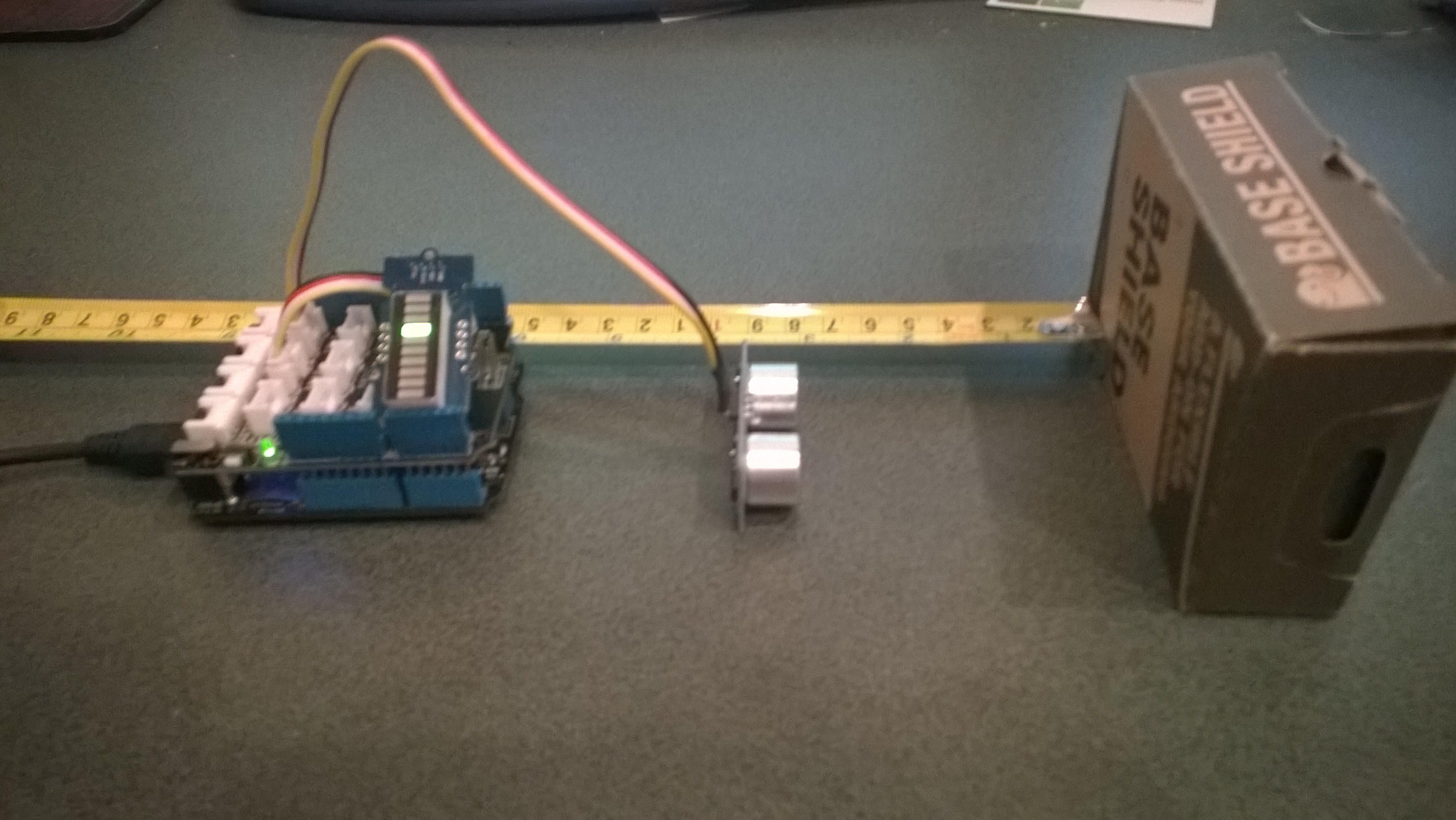
A telemetry system could be used to monitor the progress of your electric vehicle and provide feedback to the team & driver about how efficiently/fast it is being driven. As part of a telemetry system lateral, longitudinal, and vertical acceleration could be monitored using a cheap ADXL345 mems accelerometer

Netduino based 3D GMeter

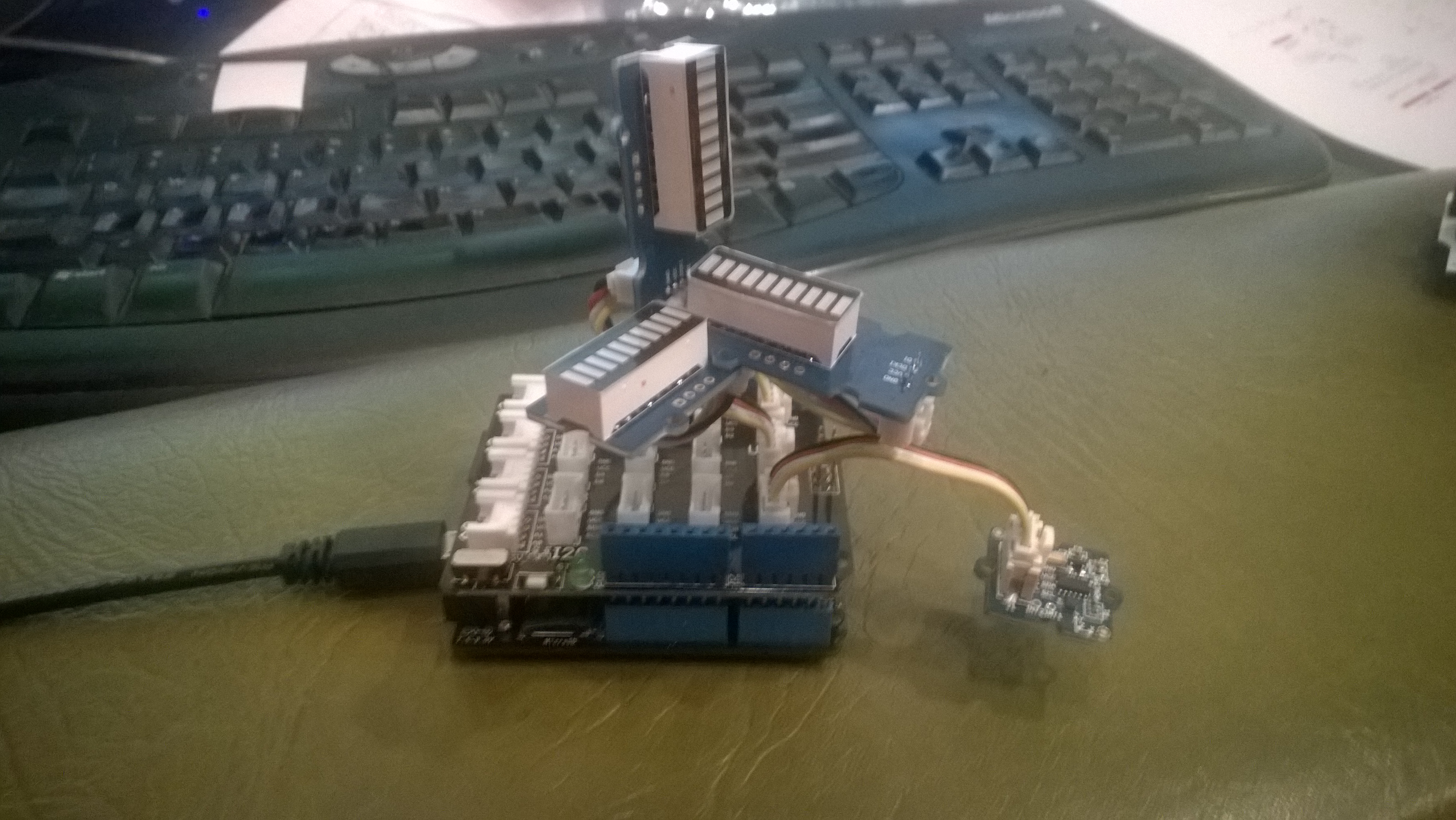
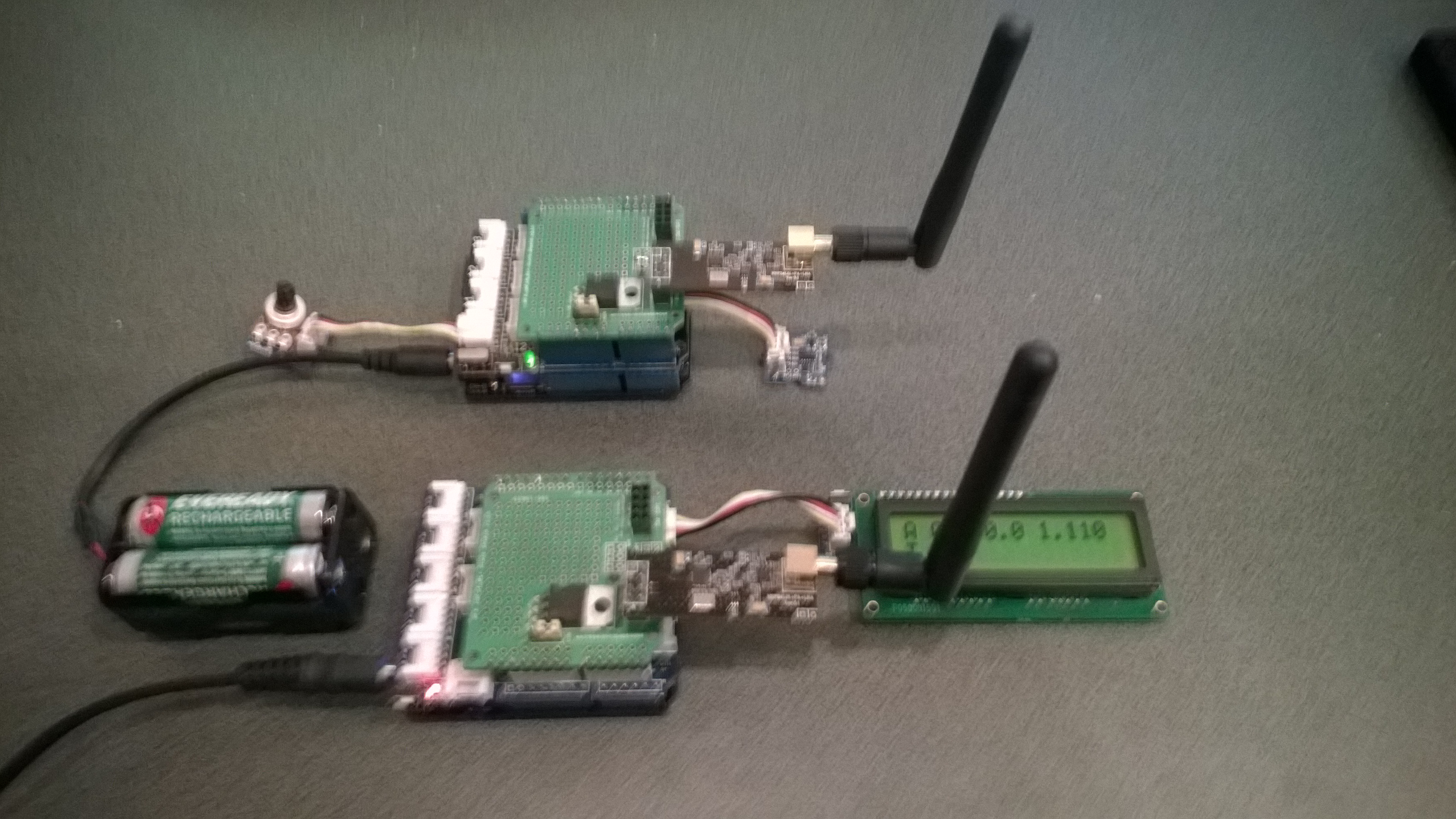
Netduino based 3D G-Meter

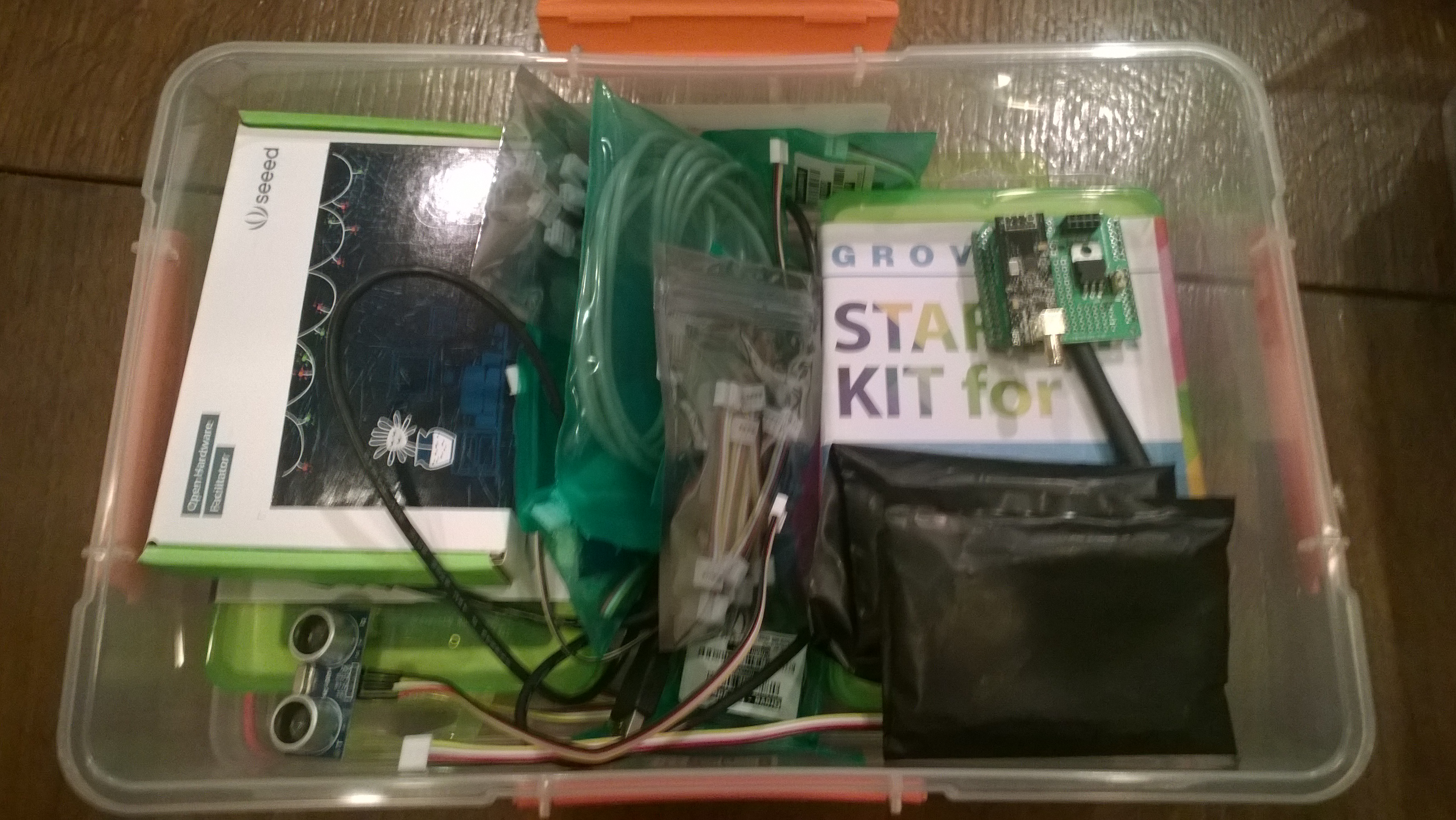
Bill of Materials for my engineering proof of concept (Prices as at May 2015)

The sample code reads the acceleration data from the ADXL345 using a driver originally created by Love Electronics. It then displays the magnitude of the scaled acceleration on 3 x LED Bars using code written by Famoury Toure

OutputPort Xcin = new OutputPort(Pins.GPIO_PIN_D0, false);
OutputPort Xdin = new OutputPort(Pins.GPIO_PIN_D1, false);
OutputPort Ycin = new OutputPort(Pins.GPIO_PIN_D3, false);
OutputPort Ydin = new OutputPort(Pins.GPIO_PIN_D4, false);
OutputPort Zcin = new OutputPort(Pins.GPIO_PIN_D5, false);
OutputPort Zdin = new OutputPort(Pins.GPIO_PIN_D6, false);

GroveLedBarGraph Xbar = new GroveLedBarGraph(Xcin, Xdin);
GroveLedBarGraph Ybar = new GroveLedBarGraph(Ycin, Ydin);
GroveLedBarGraph Zbar = new GroveLedBarGraph(Zcin, Zdin);

using (OutputPort i2cPort = new OutputPort(Pins.GPIO_PIN_SDA, true))
{
   i2cPort.Write(false);
}

ADXL345 accel = new ADXL345(0x53);
accel.EnsureConnected();
accel.Range = 2;
accel.FullResolution = true;
accel.EnableMeasurements();
accel.SetDataRate(0x0F);

while (true)
{
   accel.ReadAllAxis();

   uint xValue = (uint)(((accel.ScaledXAxisG / 1.0 ) + 1.0) * 5.0) ;
   uint xbar = 1;
   xbar = xbar << (int)xValue;
   Xbar.setLED(xbar);

   uint yValue = (uint)(((accel.ScaledYAxisG / 1.0) + 1.0) * 5.0);
   uint ybar = 1;
   ybar = ybar << (int)yValue;
   Ybar.setLED(ybar);

   uint zValue = (uint)((-(accel.ScaledZAxisG / 1.0) + 2.0) * 5.0);
   uint zbar = 1;
   zbar = zbar << (int)zValue;
   Zbar.setLED(zbar);

   Thread.Sleep(20);
   }
}

St Margaret’s CodeClub information

If you want to follow along at home all the software is free (Visual Studio Express 2013) or open source (Netduino software & Hardware + NetMF) and can be downloaded from the following locations. The packages need to be sequentially installed in the order below.

If you want to purchase your own hardware, we use Netduino 2 Plus devices (we use them mainly for their integrated networking and MicroSD card) and Seeedstudio Grove sensors. (Prices as at 05/2015)

We are looking into Apple friendly options for later this term.

CodeClub Internet of Things Boxes sponsored by Microsoft NZ

A few months ago Microsoft NZ donated NZ6K to CodeClub NZ for the purchase of kits for our basic electronics and programming classes.

Over the last couple of months I have been assembling these so we now have 15 kits ready to go. Each one has enough gear for 2-6 students, fits into a 7L Sistema plastic box and contains the following items

2 x Netduino 2 Plus devices
2 x Seeedstudio Grove Starter kits for Arduino which contain

  • 1xBase Shield
  • 1xGrove – LCD RGB Backlight
  • 1xGrove – Smart Relay
  • 1xGrove – Buzzer
  • 1xGrove – Sound Sensor
  • 1xGrove – Touch Sensor
  • 1xGrove – Rotary Angle Sensor
  • 1xGrove – Temperature Sensor
  • 1xGrove – Light Sensor
  • 1xGrove – Button
  • 1xGrove LED Blue-Blue
  • 1xGrove LED Green-Green
  • 1xGrove  LED Red-Red
  • 1xMini Servo
  • 10xGrove Cables
  • 1x9V to Barrel Jack Adapter
  • 1xGrove starter kit Manual
  • 1xGreen Plastic Box
  • 1 x ultrasonic ranger

In addition to the Netduino devices and the Grove starter kits, we also include

Thanks to Embedded coolness, Secret Labs, and Seeedstudio which discounted their products so our funding went further.

CodeClub Programming and electronics kits

CodeClub Programming and electronics kits

EVolocity Innovation Challenge Parking Aids

At evelocity boot camp on the 22nd of March we talked about aids for use in the parking challenge. For example, a Netduino and one or more ultrasonic rangers could be used to measure the distance to obstacles placed around the car park.

In the picture below the LED bar is displaying the distance to the base shield box with each LED segment representing 2cm.
Netduino based Park Distance Control

Bill of Materials for this project (Prices as at March 2015)

This code is just to illustrate how this could done and should not be used in production

public class Program
{
   private static OutputPort triggerOutput;
   private static InterruptPort echoInterrupt;
   private static long pulseStartTicks;
   private static GroveLedBarGraph distanceBar;
   private const int MillimetersPerBar = 20;

   public static void Main()
   {
      OutputPort distanceCin = new OutputPort(Pins.GPIO_PIN_D8, false);
      OutputPort distanceDin = new OutputPort(Pins.GPIO_PIN_D9, false);

      distanceBar = new GroveLedBarGraph(distanceCin, distanceDin);

      triggerOutput = new OutputPort(Pins.GPIO_PIN_D5, false);
      echoInterrupt = new InterruptPort(Pins.GPIO_PIN_D4,
         true,
         Port.ResistorMode.Disabled,
         Port.InterruptMode.InterruptEdgeBoth);

      echoInterrupt.OnInterrupt += new NativeEventHandler(echoInterruptPort_OnInterrupt);

      Timer distanceUpdate = new Timer(distanceUpdateCallbackProc, null, 0, 500);

      Thread.Sleep(Timeout.Infinite);
   }

   public static void distanceUpdateCallbackProc(object state)
   {
      triggerOutput.Write(false);
      Thread.Sleep(2);
      triggerOutput.Write(true);
      Thread.Sleep(10);
      triggerOutput.Write(false);
      Thread.Sleep(2);
   }

   static void echoInterruptPort_OnInterrupt(uint data1, uint data2, DateTime time)
   {
      long pulseWidthTicks;

      if (data2 == 1) // leading edge, start of pulse
      {
         pulseStartTicks = time.Ticks;
      }
      else
      {
         pulseWidthTicks = time.Ticks - pulseStartTicks;

         long distance = pulseWidthTicks / 58;

         Debug.Print("distance = " + distance.ToString() + "mm");

         uint ledBar = 1;
         ledBar = ledBar <<(int)(distance / MillimetersPerBar );
         distanceBar.setLED(ledBar);
      }
   }
}

CodeClub Mashup 2014 @ Epic Innovation

On the 8th of November  I was an industry mentor at CodeClub Mashup 2014 which was held at Epic Innovation in Christchurch.

The event was sponsored by Environment Canterbury (ECAN), Land Information New Zealand (LINZ) and Code Club Aotearoa.

Mashup 2014 was a “concept to cash” in one day competition for local high schools. We had roughly 40 students turn up and we started the day with introductions to hardware/software based product development and basic business skills.

Mashup2014 Judging begins

Mashup2014 Judging begins

A team from a Selwyn House an Independent School for Girls from year 1 – 8 explained in a blog post what is mashup.

Some students from Burnside High School produced the official video about the day

Thinking about “Internet of Things” and/or “Farm of Things” mashups in Q1 2015


Netduino Galvanic Skin Response(GSR)

One of CodeClub’s sponsors is Orion Health so I have been evaluating sensors suitable for health focused projects. We already use the SeeedStudio Grove Heart rate sensor and Grove EMG Detector, so I purchased a Grove GSR sensor for testing. Galvanic Skin Response(GSR) is a method of measuring the electrical conductivity of the skin, which depends on the amount of sweat on the skin.

Netduino with Grove GSR sensor

Netduino with Grove GSR sensor

The GSR detector outputs a single analog signal which I connected to A0. For the evaluation I averaged the first 3000 samples to determine the initial offset, then sampled roughly every 100mSec.

I’m a bit worried about the robustness of the wires connecting the two probes to the black cable so it will be interesting to see how long they last at Code Club.

I also updated the Minimum and Maximum values with each sample as this appeared to make the display more reliable.

I found the display responded well to me holding my breath for as long as I could.

Pulse rate + EMG + GSR = Polygraph or DIY lie detector maybe a project for next term.

for (int sampleCounter = 0; sampleCounter < calibrationSampleCount; sampleCounter++)
{
   double value = gsr.Read();
   sampleSum += value;
}
offset = sampleSum / calibrationSampleCount ;

I then displayed the magnitude of the adjusted signal on a Seeedstudio LED bar using code written by Famoury Toure

while(true)
{
   double value = emg.Read() - offset;

   if (value < valueMinimum)
   {
      valueMinimum = value;
   }

   if (value > valueMaximum)
   {
      valueMaximum = value;
   }
   range = valueMaximum - valueMinimum;
   if (value < 0)
   {
      value = value / valueMaximum * 10.0;
   }
   else
   {
      value = value / valueMinimum * 10.0;
   }
   Debug.Print("Val " + value.ToString("F3") + " Max " + valueMaximum.ToString("F3") + " Min " +valueMinimum.ToString("F3"));

   int bar = 1;
   value = 10.0 - value;
   bar = bar << (int)value ;
   ledBar.setLED((uint)bar);
   Thread.Sleep(100);
}

Bill of Materials (Prices as at October 2014)

EV Telemetry Demo

At EV Camp in June 2014 I talked about real-time telemetry for the electric carts. This is a demo of how this could be done using a couple of Netduinos, nRF24L01 modules and some other hardware

Telemetry Demo

Accelerometer and Throttle Position Telemetry

Bill of materials (Prices as at July 2014)

  • 2 x Netduino Plus 2 USD60,NZD108 or Netduino 2 USD33,NZD60
  • 2 x Embedded Coolness nRF24L01shields V1.1b + high power modules AUD17.85
  • 2 x Grove Base Shields V2 USD8.90
  • 1 x Grove ADX345 Accelerometer USD9.90
  • 1 x Grove Rotary Angle Sensor USD2.90
  • 1 x Grove 16×2 LCD USD13.90 (Using earlier serial display in pictures)

The mobile device configures the Gralin nRF24L01 library, initialises the Love Electronics ADXL345 Accelerometer library, and creates two timers, one for the throttle position the other for the accelerometer.

_module.OnTransmitFailed += OnSendFailure;
_module.OnTransmitSuccess += OnSendSuccess;
_module.Initialize(SPI.SPI_module.SPI1, Pins.GPIO_PIN_D7, Pins.GPIO_PIN_D3, Pins.GPIO_PIN_D2);
_module.Configure(myAddress, channel);
_module.Enable();

accel.EnsureConnected();
accel.Range = 2;
accel.FullResolution = true;
accel.EnableMeasurements();
accel.SetDataRate(0x0F);

Timer throttlePositionUpdates = new Timer(throttleTimerProc, null, 500, 500);
Timer accelerometerUpdates = new Timer(AccelerometerTimerProc, null, 500, 500);

Thread.Sleep( Timeout.Infinite ) ;

The Accelerometer timer reads the x, y & z accelerations then sends the data as an ASCII string (rather than Unicode) to save space (maximum message length is 32 bytes)

private void AccelerometerTimerProc(object state)
{
accel.ReadAllAxis();
Debug.Print("A- X = " + accel.ScaledXAxisG.ToString("F2") + " Y = " + accel.ScaledYAxisG.ToString("F2") + " Z = " + accel.ScaledZAxisG.ToString("F2"));

_module.SendTo(baseStationAddress, Encoding.UTF8.GetBytes("A " + accel.ScaledXAxisG.ToString("F1") + " " + accel.ScaledYAxisG.ToString("F1") + " " + accel.ScaledZAxisG.ToString("F1")));
}

The base station works in a similar way, configuring the nRF24L01 library then displaying the received messages on the LCD Display.

Remote control 4WD robot build part2

I finally had some time to finish off the 4WD robot I first blogged about in February this year.

robot and remote control

Netduino 4wd robot and remote control unit

When I fired up the robot the nrf24L01 module on the embedded coolness shield was having some problems with electrical noise from the motors. This noise was causing the wireless module to report errors then stop working. So, based on this article by Pololu I added some noise suppression capacitors. There are two 0.1uF capacitors per motor and they connect the power supply pins to the metal casing of the motor. I have also twisted the motor supply wires and added some capacitors to the motor shield.

Motors with noise suppression capacitors

Netduino 4WD Robot motors with noise suppression capacitors

The Elecfreaks Joystick has to be modified to work with a Netduino. The remote control uses the initial position of the joystick for a calibration offset then sends 4 byte commands to the robot every 250mSec. The first two bytes are the motor directions and the last two are the motor speeds.

_module.OnDataReceived += OnReceive;
_module.OnTransmitFailed += OnSendFailure;
_module.OnTransmitSuccess += OnSendSuccess;

_module.Initialize(SPI.SPI_module.SPI1, Pins.GPIO_PIN_D10, Pins.GPIO_PIN_D9, Pins.GPIO_PIN_D1);
_module.Configure(_ControllerAddress, channel);
_module.Enable();

xOffset = xAxis.Read();
yOffset = yAxis.Read();

_timer = new Timer(SendMessage, null, 250, 250);
Thread.Sleep(Timeout.Infinite);

Then

byte[] command = { motor1Direction, motor2Direction, motor1Speed, motor2Speed };
_module.SendTo(_RobotAddress, command);

After trialling the robot round the house I added a timer to shut the motors down if connectivity was lost. Before adding the noise suppression capacitors I managed to plough the robot into the wall when the radio link failed and the motors were running at close to full speed.

Timer CommunicationsMonitorTimer = newTimer(CommunicationsMonitorTimerProc, null, 500, 500);
void CommunicationsMonitorTimerProc(object status)
{
   if (( DateTime.UtcNow - _MessageLastReceivedAt ) > MessageMaximumInterval)
   {
      Debug.Print(&quot;Communications timeout&quot;);
      M1Speed.DutyCycle = 0.0;
      M2Speed.DutyCycle = 0.0;
   }
}

Electric Vehicle Camp 2014-06

The Hardware

The software

Flash an LED

OutputPort led = new OutputPort(Pins.ONBOARD_LED, false);
while ( true)
{
   Led.Write(!Led.Read())
   Thread.Sleep(500)
}

Digital Input – Polled

InputPort button = new InputPort(Pins.ONBOARD_SW1, false, Port.ResistorMode.Disabled);
OutputPort led = new OutputPort(Pins.ONBOARD_LED, false);
while (true)
{
   led.Write(button.Read());
   Thread.Sleep(1000);
}

Digital Input – Interrupt

static OutputPort interuptled = new OutputPort(Pins.ONBOARD_LED, false);
InterruptPort button = new InterruptPort(Pins.ONBOARD_SW1, false, Port.ResistorMode.Disabled, Port.InterruptMode.InterruptEdgeHigh);
button.OnInterrupt += new NativeEventHandler(button_OnInterrupt);&amp;amp;lt;/span&amp;amp;gt;&amp;amp;lt;/code&amp;amp;gt;

Thread.Sleep(Timeout.Infinite);
static void button_OnInterrupt(uint data1, uint data2, DateTime time)
{
   interuptled.Write(!interuptled.Read());
}

Analog Input

AnalogInput Sensor = new AnalogInput(Cpu.AnalogChannel.ANALOG_0);
while ( true)
{
   Debug.Print( &quot;Value &quot; + Sensor.Read(&quot;F2&quot;));
   Thread.Sleep(500)
}

Pulse Width Modulation Output

AnalogInput brightness = new AnalogInput(AnalogChannels.ANALOG_PIN_A0);
PWM led = new PWM(PWMChannels.PWM_PIN_D5, 1000, 0.0, false);

led.Start();

while (true)
{
   Debug.Print(&amp;amp;quot;Brightness &amp;amp;quot; + led.DutyCycle.ToString("F2"));
   led.DutyCycle = brightness.Read();
   Thread.Sleep(500);
}
led.Stop();

Telemetry – Mobile station

Configure the NRF24L01 library for the  elecfreaks Joystick ShieldV2.4, for more detail see this post 

_module.OnDataReceived += OnReceive;
_module.OnTransmitFailed += OnSendFailure;
_module.OnTransmitSuccess += OnSendSuccess;
_module.Initialize(SPI.SPI_module.SPI1, Pins.GPIO_PIN_D10, Pins.GPIO_PIN_D9, Pins.GPIO_PIN_D1);
_module.Configure(myAddress, channel);
_module.Enable();

Timer joystickPositionUpdates = new Timer(JoyStickTimerProc, null, 500, 500);
Thread.Sleep( Timeout.Infinite ) ;

Send the data to the base station (converting it from Unicode to ASCII)

private void JoyStickTimerProc(object state)
{
   double xVal = x.Read();
   double yVal = y.Read();
   Debug.Print("X " + xVal.ToString("F1") + " Y &" + yVal.ToString("F1"));

   _module.SendTo(baseStationAddress, Encoding.UTF8.GetBytes( xVal.ToString("F1") + " " + yVal.ToString("F1")));
}

Telemetry – Base Station

Configure the NRF24L01 library for the Embedded Coolness board, for more detail see this post

private readonly NRF24L01Plus _module;

_module.OnDataReceived += OnReceive;
_module.OnTransmitFailed += OnSendFailure;
_module.OnTransmitSuccess += OnSendSuccess;

_module.Initialize(SPI.SPI_module.SPI1, Pins.GPIO_PIN_D7, Pins.GPIO_PIN_D3, Pins.GPIO_PIN_D2);
_module.Configure(_myAddress, channel);
_module.Enable();

Display the inbound message (converting it from ASCII to Unicode)

private void OnReceive(byte[] data)
{
string message = new String(Encoding.UTF8.GetChars(data));
Debug.Print("Receive " + message); ;
}

Code Camp Christchurch 2014

The Hardware

Flash an LED

OutputPort led = new OutputPort(Pins.ONBOARD_LED, false);
while ( true)
{
   Led.Write(!Led.Read())
   Thread.Sleep(500)
}

Digital Input – Polled

InputPort button = new InputPort(Pins.ONBOARD_SW1, false, Port.ResistorMode.Disabled);
OutputPort led = new OutputPort(Pins.ONBOARD_LED, false);
while (true)
{
   led.Write(button.Read());
   Thread.Sleep(1000);
}

Digital Input – Interrupt

static OutputPort interuptled = new OutputPort(Pins.ONBOARD_LED, false);
InterruptPort button = new InterruptPort(Pins.ONBOARD_SW1, false, Port.ResistorMode.Disabled, Port.InterruptMode.InterruptEdgeHigh);
button.OnInterrupt += new NativeEventHandler(button_OnInterrupt);

Thread.Sleep(Timeout.Infinite);

static void button_OnInterrupt(uint data1, uint data2, DateTime time)
{
   interuptled.Write(!interuptled.Read());
}

Analog Input

AnalogInput Sensor = new AnalogInput(Cpu.AnalogChannel.ANALOG_0);
while ( true)
{
   Debug.Print( "Value " + Sensor.Read().ToString("F2"));
   Thread.Sleep(500);
}

Pulse Width Modulation Output

AnalogInput brightness = new AnalogInput(AnalogChannels.ANALOG_PIN_A0);
PWM led = new PWM(PWMChannels.PWM_PIN_D5, 1000, 0.0, false);

led.Start();
while (true)
{
   Debug.Print("Brightness " + led.DutyCycle.ToString("F2"));
   led.DutyCycle = brightness.Read();
   Thread.Sleep(500);
}
led.Stop();

Power Consumption Monitor

Developing the software for the Energy Monitor Shield

Robot

Developing the software

  • Determine the distance to objects
  • Control the speed & direction of the motors using a Motor Shield Driver
  • Basic obstacle avoidance
  • Avoid obstacles using a state machine
  • Fine tune the motor speeds using a rotary encoder
  • Connect the GPS
  • Upload the position information to Xively

Heart Rate Monitor

Developing the software

  • Read the buttons using an AnalogInput
  • Count the number of button presses using an InterruptPort and a Timer
  • Determine the pulse rate in BPM by counting
  • Determine the average pulse rate in BPM
  • Display and manage the pulse rate info on the DFRobot 16×2 Lcd Shield
  • Upload the pulse rate information to xively