Remote control 4WD robot build part2

I finally had some time to finish off the 4WD robot I first blogged about in February this year.

robot and remote control

Netduino 4wd robot and remote control unit

When I fired up the robot the nrf24L01 module on the embedded coolness shield was having some problems with electrical noise from the motors. This noise was causing the wireless module to report errors then stop working. So, based on this article by Pololu I added some noise suppression capacitors. There are two 0.1uF capacitors per motor and they connect the power supply pins to the metal casing of the motor. I have also twisted the motor supply wires and added some capacitors to the motor shield.

Motors with noise suppression capacitors

Netduino 4WD Robot motors with noise suppression capacitors

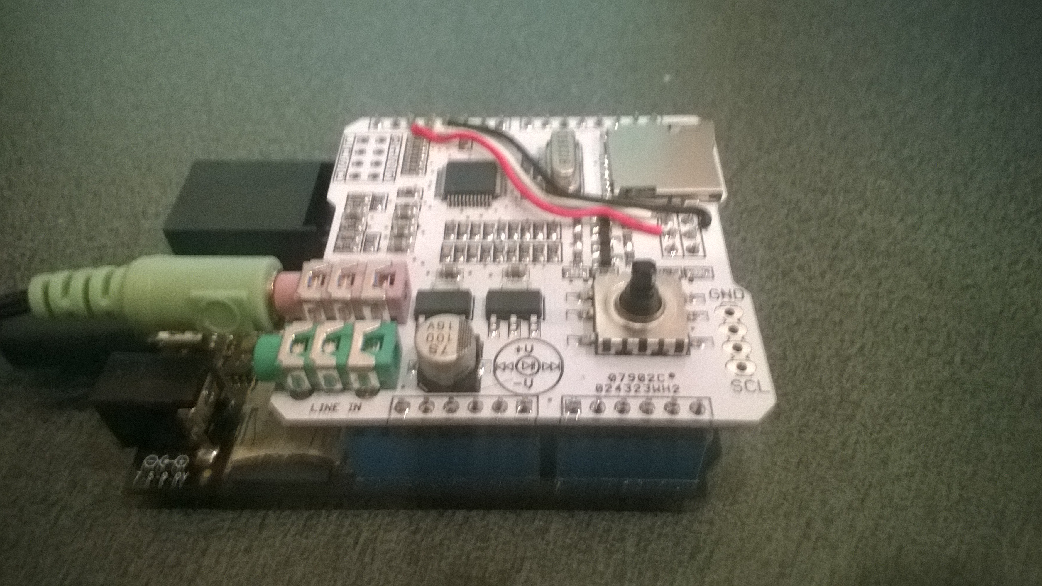
The Elecfreaks Joystick has to be modified to work with a Netduino. The remote control uses the initial position of the joystick for a calibration offset then sends 4 byte commands to the robot every 250mSec. The first two bytes are the motor directions and the last two are the motor speeds.

_module.OnDataReceived += OnReceive;
_module.OnTransmitFailed += OnSendFailure;
_module.OnTransmitSuccess += OnSendSuccess;

_module.Initialize(SPI.SPI_module.SPI1, Pins.GPIO_PIN_D10, Pins.GPIO_PIN_D9, Pins.GPIO_PIN_D1);
_module.Configure(_ControllerAddress, channel);
_module.Enable();

xOffset = xAxis.Read();
yOffset = yAxis.Read();

_timer = new Timer(SendMessage, null, 250, 250);
Thread.Sleep(Timeout.Infinite);

Then

byte[] command = { motor1Direction, motor2Direction, motor1Speed, motor2Speed };
_module.SendTo(_RobotAddress, command);

After trialling the robot round the house I added a timer to shut the motors down if connectivity was lost. Before adding the noise suppression capacitors I managed to plough the robot into the wall when the radio link failed and the motors were running at close to full speed.

Timer CommunicationsMonitorTimer = newTimer(CommunicationsMonitorTimerProc, null, 500, 500);
void CommunicationsMonitorTimerProc(object status)
{
   if (( DateTime.UtcNow - _MessageLastReceivedAt ) > MessageMaximumInterval)
   {
      Debug.Print("Communications timeout");
      M1Speed.DutyCycle = 0.0;
      M2Speed.DutyCycle = 0.0;
   }
}

Energy Monitor Shield Nokia 5100 Display

The Energy Monitor Shield is supplied with a Nokia 5110 LCD for displaying instantaneous power consumption etc. There is an excellent Netduino driver for the Nokia 5100 display by omar, and with a few modifications this works with the Energy Monitor Shield. I removed the backlight support and made a few other simple modifications.

Nokia_5110 Lcd = new Nokia_5110(Pins.GPIO_PIN_D3, Pins.GPIO_PIN_D6, Pins.GPIO_PIN_D5);

while (true)
{
   Lcd.Clear();
   Lcd.DrawString(0, 0, DateTime.Now.ToString("HH:mm:ss"), true);
   Lcd.DrawString(0, 1, DateTime.Now.ToString("HH:mm:ss"), true);
   Lcd.DrawString(0, 2, DateTime.Now.ToString("HH:mm:ss"), true);
   Lcd.Refresh();
   Thread.Sleep(500)
}

Netduino Nokia 5110 driver

Energy Monitor Shield Noise Reduction

In a couple of previous posts the noise on the Netduino AnalogInput and the impact of this on the RMS current measurement was discussed. I trialled two versions of the code to see if my approach worked. Both versions used the initial calibration phase to measure the maximum and minimum values of the noise.

int valueSum = 0;
int valueNoiseMinimum = int.MaxValue;
int valueNoiseMaximum = int.MinValue;
int valueSumSqr = 0;
int offset;
AnalogInput x1 = new AnalogInput(Cpu.AnalogChannel.ANALOG_0);

// Calculate the sum for offset for first run
for (int i = 0; i < SampleCount; i++)
{
  int value = x1.ReadRaw();
  valueSum = valueSum + value;

   if (value < valueNoiseMinimum)
   {
      valueNoiseMinimum = value;
   }
   if (value > valueNoiseMaximum)
   {
      valueNoiseMaximum = value;
   }
}

offset = valueSum / SampleCount;
valueNoiseMinimum -= offset;
valueNoiseMaximum -= offset;

The first version used only the initial offset

Stopwatch stopwatch = Stopwatch.StartNew();
stopwatch.Start();

for (int i = 0; i < SampleCount; i++)
{
   int value = x1.ReadRaw();
   value -= offset;

   if ((value &gt; valueNoiseMaximum) || (value &lt; valueNoiseMinimum))
   {
   valueSumSqr += (value * value);
   }
}
stopwatch.Stop();

RMS 42.2729 RMS Current 3.4A RMS Power 775W Duration = 3301 mSec 30293/sec
RMS 42.2137 RMS Current 3.4A RMS Power 774W Duration = 3302 mSec 30284/sec
RMS 42.2374 RMS Current 3.4A RMS Power 775W Duration = 3302 mSec 30284/sec
RMS 42.1307 RMS Current 3.4A RMS Power 773W Duration = 3302 mSec 30284/sec
RMS 42.1189 RMS Current 3.4A RMS Power 773W Duration = 3302 mSec 30284/sec
RMS 42.1307 RMS Current 3.4A RMS Power 773W Duration = 3302 mSec 30284/sec
RMS 42.1070 RMS Current 3.4A RMS Power 772W Duration = 3302 mSec 30284/sec
RMS 42.1189 RMS Current 3.4A RMS Power 773W Duration = 3302 mSec 30284/sec
RMS 42.1426 RMS Current 3.4A RMS Power 773W Duration = 3303 mSec 30275/sec

The second version updated the offset every iteration

Stopwatch stopwatch = Stopwatch.StartNew();
stopwatch.Start();

for (int i = 0; i &lt; SampleCount; i++)
{
   int value = x1.ReadRaw();
   valueSum += value;
   value -= offset;

   if ((value &gt; valueNoiseMaximum) || (value &lt; valueNoiseMinimum))
   {
      valueSumSqr += (value * value);
   }
}
stopwatch.Stop();
offset = valueSum / SampleCount;

This was slightly slower due to the extra addition operation in the sampling loop

RMS 41.5933 RMS Current 3.3A RMS Power 763W Duration = 3537 mSec 28272/sec
RMS 41.6653 RMS Current 3.3A RMS Power 764W Duration = 3541 mSec 28240/sec
RMS 41.6053 RMS Current 3.3A RMS Power 763W Duration = 3538 mSec 28264/sec
RMS 41.5572 RMS Current 3.3A RMS Power 762W Duration = 3537 mSec 28272/sec
RMS 41.5331 RMS Current 3.3A RMS Power 762W Duration = 3537 mSec 28272/sec
RMS 41.4970 RMS Current 3.3A RMS Power 761W Duration = 3540 mSec 28248/sec
RMS 41.4849 RMS Current 3.3A RMS Power 761W Duration = 3538 mSec 28264/sec
RMS 41.4849 RMS Current 3.3A RMS Power 761W Duration = 3516 mSec 28441/sec

At 28K4 samples per second the self adjusting RMS calculation is sampling the 50Hz waveform much more frequently than required.

Energy Monitor Shield RMS Calculation

The voltage output by the current sensor and measured by the Netduino needs to be corrected using the offset value then the RMS value calculated. This RMS value then needs to be adjusted taking into account the voltage range of the Netduino analog input (0V-3V3), the resolution of the analog input (12 bits) and the voltage output by the non-invasive current sensor (0~1V for 0~30A).

My approach appears to produce reasonable values but I will need to compare them with a calibrated reference device to check its accuracy. The 18W measurement with no current flowing is due to the noise on the analog input discussed in an earlier post.

The first version of the software used the initial offset value, the second version updates the offset value at the end of each set of samples.

int valueSum = 0;
int valueSumSqr = 0;
int offset;
AnalogInput x1 = new AnalogInput(Cpu.AnalogChannel.ANALOG_0);

// Calculate the sum for initial offset
for (int i = 0; i < SampleCount; i++)
{
valueSum += x1.ReadRaw();
}
offset = valueSum / SampleCount;

Stopwatch stopwatch = Stopwatch.StartNew();
stopwatch.Start();

for (int i = 0; i < SampleCount; i++)
{
int value = x1.ReadRaw();

value -= offset;

valueSumSqr += (value * value);
}
stopwatch.Stop();

double rms = System.Math.Sqrt((double)(valueSumSqr / SampleCount));
double rmsCurrent = rms * (3.3 / 4096.0) * 3.3 * 30.0;
double rmsWatts = rmsCurrent * 230;

Duration = 2587 mSec 38654/sec RMS 1.0 RMS Current 0.1A RMS Power 18W
Duration = 2588 mSec 38639/sec RMS 1.0 RMS Current 0.1A RMS Power 18W
Duration = 2587 mSec 38654/sec RMS 1.0 RMS Current 0.1A RMS Power 18W

int valueSum = 0;
int valueSumSqr = 0;
int offset;
AnalogInput x1 = new AnalogInput(Cpu.AnalogChannel.ANALOG_0);
// Calculate the sum for initial offset
for (int i = 0; i < SampleCount; i++)
{
valueSum += x1.ReadRaw();
}
offset = valueSum / SampleCount;

Stopwatch stopwatch = Stopwatch.StartNew();
stopwatch.Start();

for (int i = 0; i < SampleCount; i++)
{
int value = x1.ReadRaw();

valueSum += value;

value -= offset;

valueSumSqr += (value * value);
}
stopwatch.Stop();

offset = valueSum / SampleCount;

double rms = System.Math.Sqrt((double)(valueSumSqr / SampleCount));
double rmsCurrent = rms * (3.3 / 4096.0) * 3.3 * 30.0 ;
double rmsWatts = rmsCurrent * 230;

Duration = 2816 mSec 35511/sec RMS 1.0 RMS Current 0.1A RMS Power 18W

Both versions appear to sample the output of the non-invasive current sensor at a more than sufficient rate.

Energy Monitor Shield Analog Input Noise

While writing the calibration code I noticed that the voltage reading was a bit noisy so I modified the code to record the minimum & maximum values then put the current sensor clamp on a wire not carrying any current.

int value;
int valueSum = 0;
int valueMinimum = int.MaxValue;
int valueMaximum = int.MinValue;
AnalogInput x1 = new AnalogInput(Cpu.AnalogChannel.ANALOG_0);

stopwatch.Start();
for (int i = 0; i < SampleCount; i++)
{
value = x1.ReadRaw();

if (value < valueMinimum)
{
valueMinimum = value;
}
if (value > valueMaximum)
{
valueMaximum = value;
}
valueSum += value;
}
stopwatch.Stop();

Duration = 3509 mSec 28498/sec Min=2031 Max=2052 Avg=2041
Duration = 3501 mSec 28563/sec Min=2031 Max=2052 Avg=2041
Duration = 3500 mSec 28571/sec Min=2031 Max=2053 Avg=2041
Duration = 3501 mSec 28563/sec Min=2031 Max=2053 Avg=2041
Duration = 3500 mSec 28571/sec Min=2031 Max=2051 Avg=2041
Duration = 3500 mSec 28571/sec Min=2031 Max=2052 Avg=2041
Duration = 3500 mSec 28571/sec Min=2031 Max=2053 Avg=2041
Duration = 3501 mSec 28563/sec Min=2032 Max=2053 Avg=2041
Duration = 3500 mSec 28571/sec Min=2031 Max=2053 Avg=2041
Duration = 3500 mSec 28571/sec Min=2030 Max=2052 Avg=2041

Looks like there is a little bit of noise on the input when there is no current flowing.

I also tried using the baked in Min & Max functions but these were a bit slower which was not what I was expecting

int value;
int valueSum = 0;
int valueMinimum = int.MaxValue;
int valueMaximum = int.MinValue;
AnalogInput x1 = new AnalogInput(Cpu.AnalogChannel.ANALOG_0);

stopwatch.Start();
for (int i = 0; i < SampleCount; i++)
{
value = x1.ReadRaw();

valueMinimum = System.Math.Min(value, valueMinimum);
valueMaximum = System.Math.Max(value, valueMaximum);

valueSum += value;
}
stopwatch.Stop();

Duration = 4672 mSec 21390/sec Min=2036 Max=2048 Avg=2041
Duration = 4665 mSec 21436/sec Min=2036 Max=2049 Avg=2041
Duration = 4665 mSec 21436/sec Min=2035 Max=2049 Avg=2041
Duration = 4664 mSec 21440/sec Min=2036 Max=2048 Avg=2041
Duration = 4664 mSec 21440/sec Min=2036 Max=2049 Avg=2041
Duration = 4664 mSec 21440/sec Min=2035 Max=2048 Avg=2041
Duration = 4664 mSec 21440/sec Min=2035 Max=2049 Avg=2041
Duration = 4664 mSec 21440/sec Min=2035 Max=2048 Avg=2041

Energy Monitor Shield Sensor Calibration

The Netduino 2 Plus AnalogInput has a range of 0V to 3V3. The Non Invasive Current Sensor we are using returns 0-1V AC for 0-30 Amps AC. To measure the sensor’s output waveform the Energy Monitor Shield uses a voltage divider to offset the reference voltage to 3v3/2. To calibrate the sensor we averaged the input voltage and over 100,000 readings.

The initial code looked like this

int value;
int valueSum = 0;
AnalogInput x1 = new AnalogInput(Cpu.AnalogChannel.ANALOG_0);

stopwatch.Start();
for (int i = 0; i < SampleCount; i++)
{
value = x1.ReadRaw();

valueSum = valueSum + value;
}
stopwatch.Stop();

Duration = 2272 mSec 44014/sec
Duration = 2273 mSec 43994/sec
Duration = 2272 mSec 44014/sec

I then modified the code to not use a temporary variable

int valueSum = 0;
AnalogInput x1 = new AnalogInput(Cpu.AnalogChannel.ANALOG_0);

stopwatch.Start();
for (int i = 0; i < SampleCount; i++)
{
valueSum = valueSum + x1.ReadRaw();
}
stopwatch.Stop();

Duration = 2181 mSec 45829/sec
Duration = 2182 mSec 45829/sec
Duration = 2181 mSec 45829/sec

The code without the temporary variable was slightly faster.


Netduino AnalogInput read rates

At CodeClub some of the students are building a netduino based power consumption monitor using an Energy Monitor Shield (with my modifications). The approach for the software was “inspired” by the Arduino code developed by the Open Energy Monitor project. First step was to confirm that the Netduino 2 Plus we were using could sample the Alternating Current(AC) waveform often enough.

The first version of the code called the Microsoft.Spot.Hardware.AnalogInput.Read method (which returns a floating point number) 100,000 times. The duration was measured using a Stopwatch class written by ChrisW of Secretlabs.

double value;
AnalogInput x1 = new AnalogInput(Cpu.AnalogChannel.ANALOG_0);

Stopwatch stopwatch = Stopwatch.StartNew();
stopwatch.Start();
for (int i = 0; i < SampleCount; i++)
{
value = x1.Read();
}
stopwatch.Stop();

Duration = 5496 mSec 18195/sec
Duration = 5497 mSec 18191/sec
Duration = 5496 mSec 18195/sec
Duration = 5497 mSec 18191/sec
Duration = 5496 mSec 18195/sec
Duration = 5497 mSec 18191/sec

The AnalogPort also has a overloaded Read method which returns an integer

int value;
AnalogInput x1 = new AnalogInput(Cpu.AnalogChannel.ANALOG_0);
stopwatch.Start();
for (int i = 0; i < SampleCount; i++)
{
value = x1.ReadRaw();
}
stopwatch.Stop();

Duration = 2081 mSec 48053/sec
Duration = 2082 mSec 48030/sec
Duration = 2081 mSec 48053/sec
Duration = 2082 mSec 48030/sec
Duration = 2081 mSec 48053/sec

There is also a Secret labs AnalogInput which has a Read method which returns an integer

int value;
SecretLabs.NETMF.Hardware.AnalogInput x1 = new SecretLabs.NETMF.Hardware.AnalogInput(Pins.GPIO_PIN_A0);
stopwatch.Start();
for (int i = 0; i < SampleCount; i++)
{
value = x1.Read();
}
stopwatch.Stop();

Duration = 8563 mSec 11678/sec
Duration = 8564 mSec 11676/sec
Duration = 8563 mSec 11678/sec

The int Microsoft.Spot.Hardware.AnalogInput.ReadRaw() appears to be  quite a bit faster than the other two approaches.

Energy Monitor Shield Sensor Box by Tardis

My initial way of connecting the current sensor for the Energy Monitor Shield was not really suitable for CodeClub. Carefully cutting the insulation with a craft knife and gently pulling out the phase wire could end really badly.

Image

I approached a local company Tardis Communications and they made Code Club these neat enclosures which ensure the students can’t come into contact with any live connections.

Image

Freaduino MP3 Music Shield

For code club one of the projects I had been considering was an MP3 player with a simple user interface (UI) based on a joystick providing track next/previous , volume up/down, and pause/play. I looked for suitable Arduino shields which had Netduino driver support. I narrowed the list down to (Prices as at April 2014) these VS1053 based shields

For Code Club I purchased 5 of the Elecfreaks Freaduino shields as the price and on-board joystick made it ideal for our application. The Freaduino MP3 Shield wiki page indicated that the following pins were used by the SPI bus

D10 – Used for SPI Chip Select.
D11 – Used for SPI MOSI.
D12 – Used for SPI MISO.
D13 – Used for SPI SCK.

I initially tried the NetduinoVS1053 library from SoftElectoTech but found that no sound was produced. I tried different pin configurations, format and bitrate music files but nothing worked. I then had a look at the shield schematic and noticed that D11/D12/D13 were not connected to the VS1053, only D10 which is used for chip selected on the MicroSD card socket was connected.

I soldered some jumpers to the board and connected the SPI pins on the ICSP socket to the D11,D12 & D13 on the edge connector and the shield now works. It would be good if elecfreaks could make the pins the SPI bus uses configurable using jumpers or similar.

Modified Freaduino Music Shield

Modified Freaduino Music Shield

The library needs to be initialised with the following pins

Player = newVs1053B(Pins.GPIO_PIN_A1, Pins.GPIO_PIN_A3, Pins.GPIO_PIN_A2, Pins.GPIO_PIN_A0);

The joystick operations can be handled with Interrupts with the following configuration

InterruptPort volumeDownButton = newInterruptPort(Pins.GPIO_PIN_D7, false, Port.ResistorMode.PullUp, Port.InterruptMode.InterruptEdgeLow);

InterruptPort volumeUpButton = newInterruptPort(Pins.GPIO_PIN_D3, false, Port.ResistorMode.PullUp, Port.InterruptMode.InterruptEdgeLow);

InterruptPort nextSongButton = newInterruptPort(Pins.GPIO_PIN_D4, false, Port.ResistorMode.PullUp, Port.InterruptMode.InterruptEdgeLow);

InterruptPort previousSongButton = newInterruptPort(Pins.GPIO_PIN_D6, false, Port.ResistorMode.PullUp, Port.InterruptMode.InterruptEdgeLow);

InterruptPort playStopButton = newInterruptPort(Pins.GPIO_PIN_D5, false, Port.ResistorMode.PullUp, Port.InterruptMode.InterruptEdgeLow);

volumeUpButton.OnInterrupt += new NativeEventHandler(volumeUpButton_OnInterrupt);

volumeDownButton.OnInterrupt += new NativeEventHandler(volumeDownButton_OnInterrupt);

nextSongButton.OnInterrupt += new NativeEventHandler(nextSongButton_OnInterrupt);

previousSongButton.OnInterrupt += new NativeEventHandler(previousSongButton_OnInterrupt);

playStopButton.OnInterrupt += new NativeEventHandler(playStopButton_OnInterrupt);

I could now play MP3 files off the SD card on my Netduino Plus 2 but couldn’t adjust the volume or change the track being played. Using an interrupt based approached for the UI also highlighted some problems with the driver code which I will discuss in a future post.

Ultrasonic Ranger Distance Measurement

I had been thinking about an Ultrasonic Tape measure as one of the projects for code club. One of the “challenges” we start each evening with was measuring how long the Netduino on board button was pressed using an InterruptPort triggering on both the leading and trailing edges. This challenge implements the core of the code required to use an Ultrasonic Ranger.

Ultrasonic Ranger connected to Netduino Plus 2

Ultrasonic Ranger Test Rig bill of Materials (April 2014)

A plug and play option would be

To make a measurement the trigger pin is strobed high, then the duration of the pulse on the echo pin represents the distance from the object. The NetMF DataTime structure represents tick as one hundred nanoseconds or one ten-millionth of a second. (There are 10,000 ticks in a millisecond) so the duration in ticks/58 is the distance in millimetres.

public UltraSonicRanger(Cpu.Pin triggerPin, Cpu.Pin echoPin)
{
   #region Diagnostic Assertions
   Debug.Assert(echoPin != Cpu.Pin.GPIO_NONE);
   Debug.Assert(triggerPin != Cpu.Pin.GPIO_NONE);
   Debug.Assert(echoPin != triggerPin);
   #endregion

   triggerOutput = new OutputPort(triggerPin, false);

   echoInterrupt = new InterruptPort(echoPin, true, Port.ResistorMode.Disabled, Port.InterruptMode.InterruptEdgeBoth);
   echoInterrupt.OnInterrupt += new NativeEventHandler(echoInterruptPort_OnInterrupt);
   echoInterrupt.DisableInterrupt();
}

void echoInterruptPort_OnInterrupt(uint data1, uint data2, DateTime time)
{
   if (data2 == 0) // falling edge, end of pulse
   {
      pulseWidthTicks = time.Ticks - pulseStartTicks;
      measurementComplete.Set();
   }
   else
   {
      pulseStartTicks = time.Ticks;
   }
}

Ultrasonic Ranger module source

I was pleasantly surprised by the sub 0.5 cm accuracy of the sensor