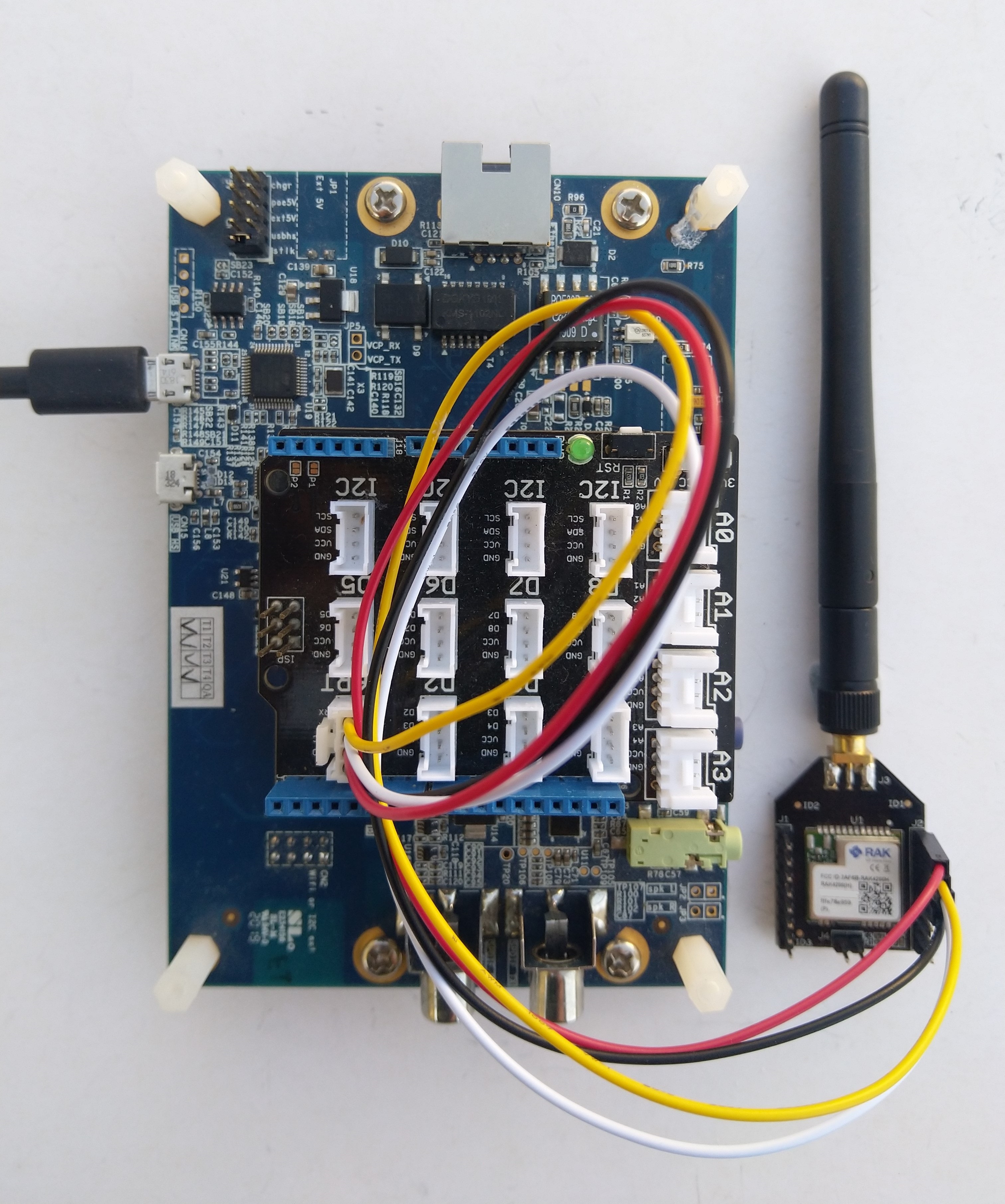
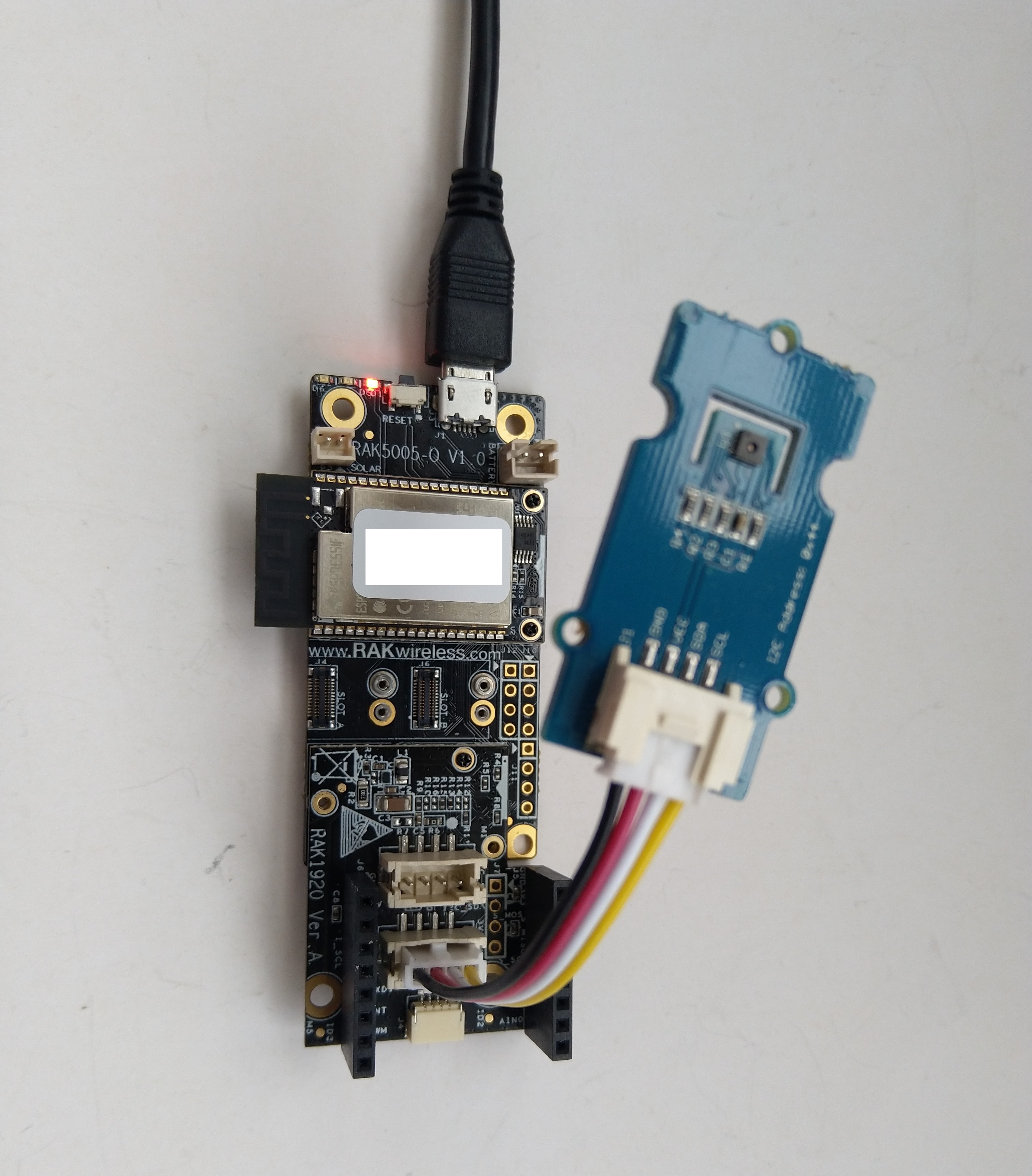
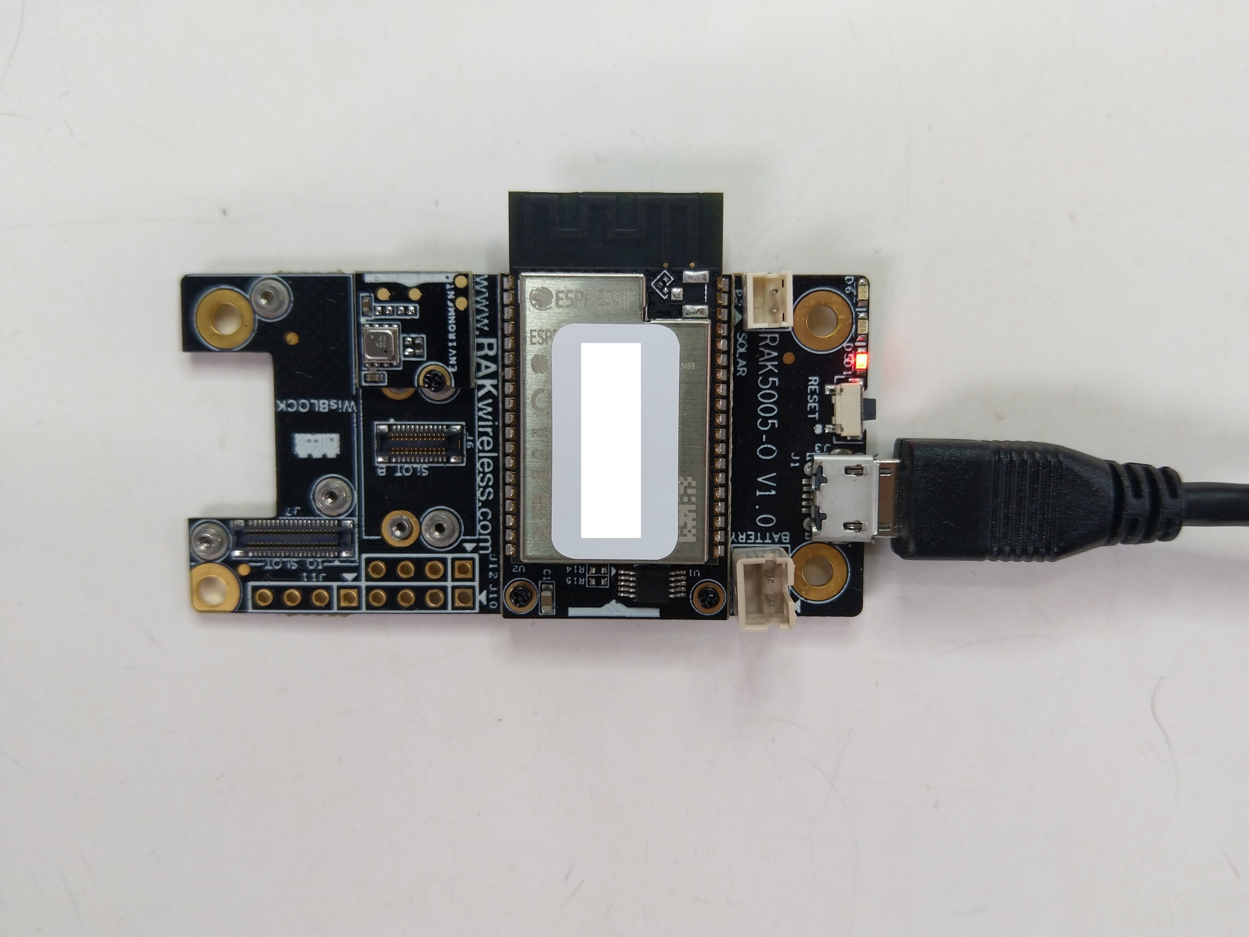
After some experimentation could get a RAK2305 WisBlock Wifi Interface Module running the .NET nanoFramework plugged into the IO Slot of RAK4200 Evaluation Board to send AT Commands to the RAK4200 Module.

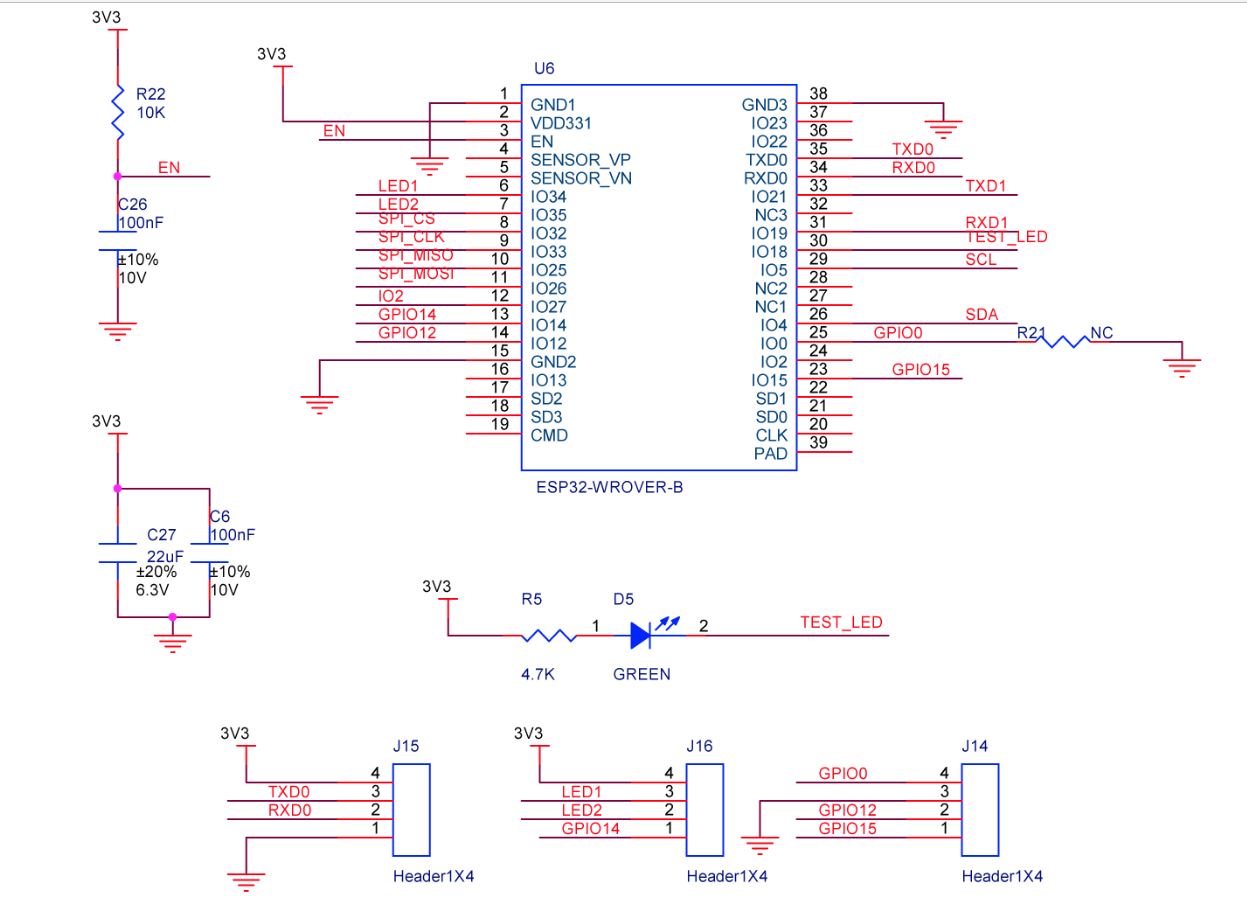
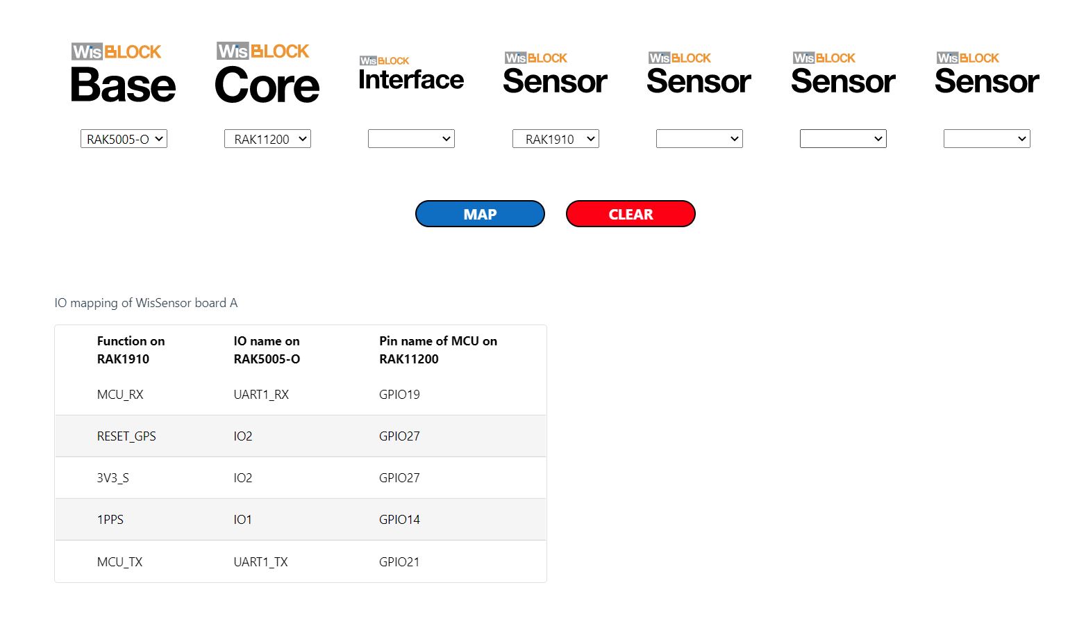
After reviewing the RAK4200 Evaluation Board and RAK2305 WisBlock Wifi Interface Module schematics I realised that the Universal Asynchronous Receiver-Transmistted(UART) transmit and receive pins had to be reversed the with the nanoFramwork ESP32 specific Configuration.SetPinFunction.
namespace devMobile.IoT.LoRaWAN.nanoFramework.RAK4200
{
using System;
using System.Diagnostics;
using System.IO.Ports;
using System.Threading;
using global::nanoFramework.Hardware.Esp32; //need NuGet nanoFramework.Hardware.Esp32
public class Program
{
private static SerialPort _SerialPort;
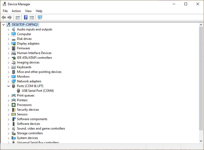
private const string SerialPortId = "COM2";
public static void Main()
{
Thread.Sleep(5000);
#if SERIAL_THREADED_READ
Thread readThread = new Thread(SerialPortProcessor);
#endif
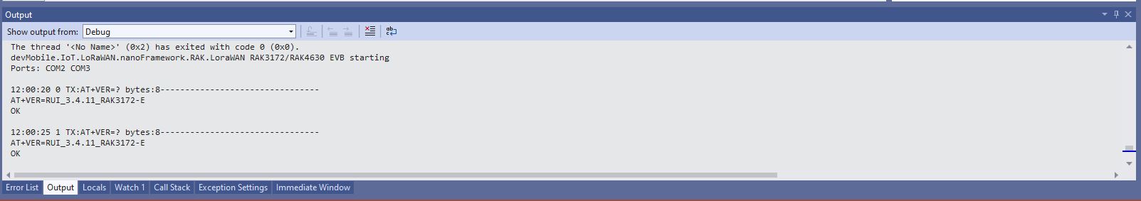
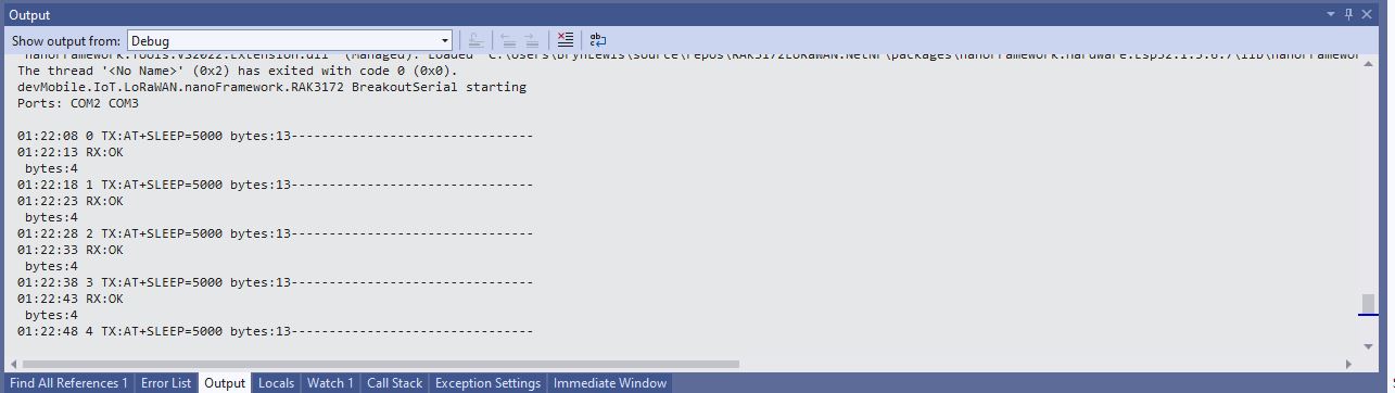
Debug.WriteLine("devMobile.IoT.LoRaWAN.nanoFramework.RAK4200 BreakoutSerial starting");
try
{
// set GPIO functions for COM2 (this is UART1 on ESP32)
Configuration.SetPinFunction(Gpio.IO21, DeviceFunction.COM2_TX);
Configuration.SetPinFunction(Gpio.IO19, DeviceFunction.COM2_RX);
Debug.Write("Ports:");
foreach (string port in SerialPort.GetPortNames())
{
Debug.Write($" {port}");
}
Debug.WriteLine("");
using (_SerialPort = new SerialPort(SerialPortId))
{
// set parameters
//_SerialPort.BaudRate = 9600;
_SerialPort.BaudRate = 115200;
_SerialPort.Parity = Parity.None;
_SerialPort.DataBits = 8;
_SerialPort.StopBits = StopBits.One;
_SerialPort.Handshake = Handshake.None;
_SerialPort.NewLine = "\r\n";
//_SerialPort.ReadBufferSize = 128;
//_SerialPort.ReadBufferSize = 256;
_SerialPort.ReadBufferSize = 512;
//_SerialPort.ReadBufferSize = 1024;
_SerialPort.ReadTimeout = 1000;
//_SerialPort.WatchChar = '\n'; // May 2022 WatchChar event didn't fire github issue https://github.com/nanoframework/Home/issues/1035
_SerialPort.DataReceived += SerialDevice_DataReceived;
_SerialPort.Open();
_SerialPort.WatchChar = '\n';
for (int i = 0; i < 5; i++)
{
string atCommand;
atCommand = "at+version";
//atCommand = "at+set_config=device:uart:1:9600";
//atCommand = "at+get_config=lora:status";
//atCommand = "at+get_config=device:status";
//atCommand = "at+get_config=lora:channel";
//atCommand = "at+help";
//atCommand = "at+set_config=device:restart";
//atCommand = "at+set_config=lora:default_parameters";
//atCommand = "at+set_config=lora:work_mode:0";
Debug.WriteLine("");
Debug.WriteLine($"{i} TX:{atCommand} bytes:{atCommand.Length}--------------------------------");
_SerialPort.WriteLine(atCommand);
Thread.Sleep(5000);
}
}
Debug.WriteLine("Done");
}
catch (Exception ex)
{
Debug.WriteLine(ex.Message);
}
}
private static void SerialDevice_DataReceived(object sender, SerialDataReceivedEventArgs e)
{
SerialPort serialPort = (SerialPort)sender;
switch (e.EventType)
{
case SerialData.Chars:
break;
case SerialData.WatchChar:
string response = serialPort.ReadExisting();
Debug.Write(response);
break;
default:
Debug.Assert(false, $"e.EventType {e.EventType} unknown");
break;
}
}
}
}
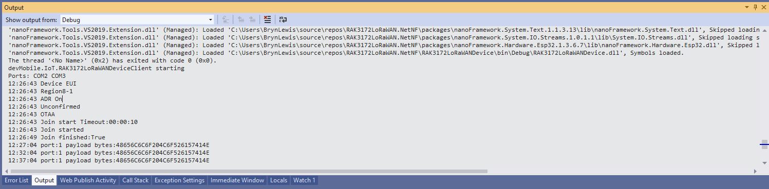
When I requested the version information with “at+version” the RAK4200 Module responded with version information.