Netduino Water flow Sensor

A few months ago I purchased 1/2” and 3/4″ inch water flow sensors from SeeedStudio. My plan was to monitor our water and power consumption data to see what environmental impact my house has.

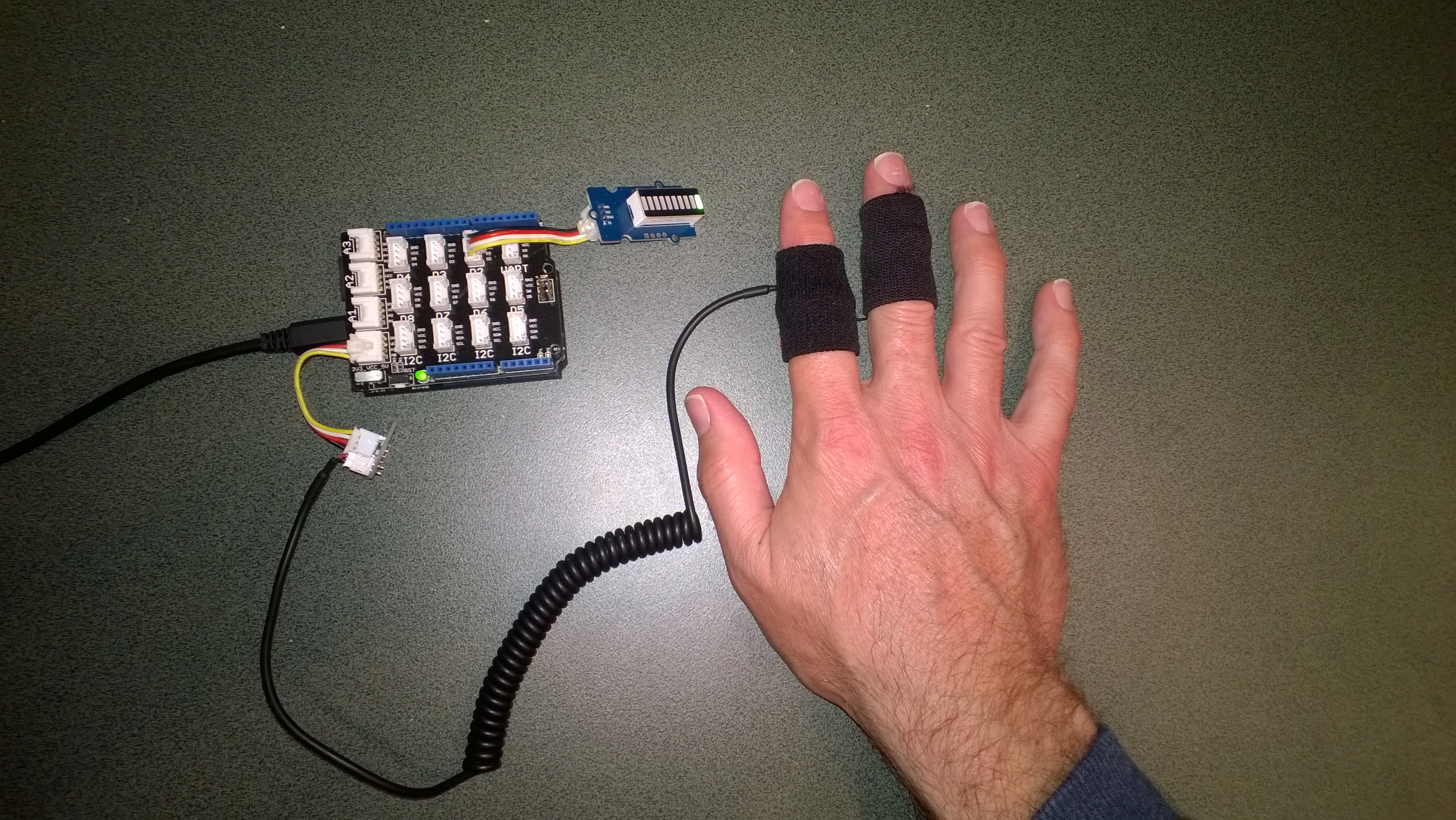
To see how the sensor works I built a simple proof of concept Netduino application which counted the pulses produced by the sensor and calculated the instantaneous water flow.

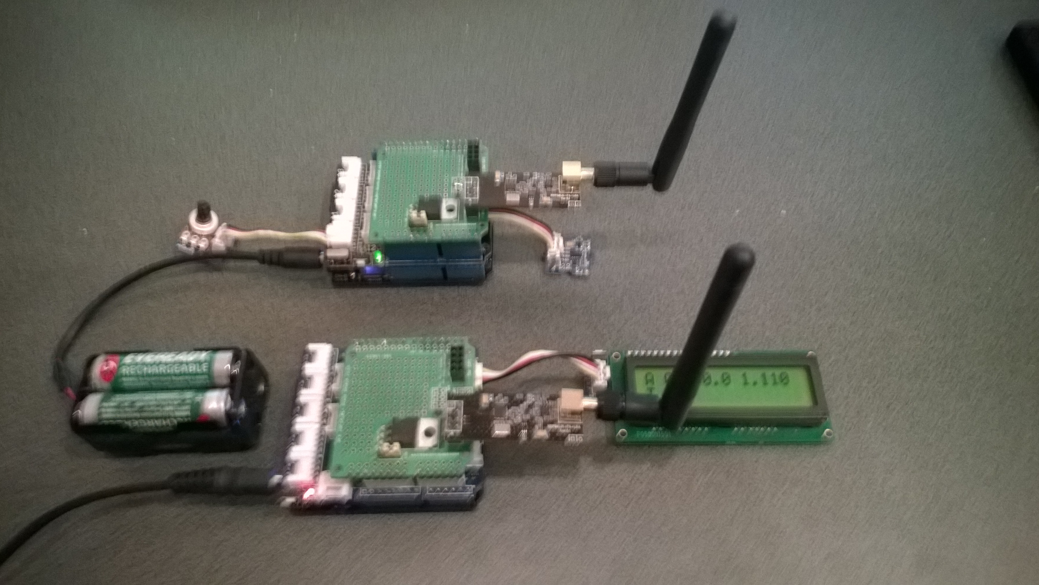
The next steps are to upload the water flow data to the cloud over a cabled then wireless connections.

public class Program
{
   private static int waterFlowCounter = 0;

   public static void Main()
   {
      InterruptPort flowCounterSensor = new InterruptPort(Pins.GPIO_PIN_D5, false, Port.ResistorMode.Disabled, Port.InterruptMode.InterruptEdgeHigh);
      flowCounterSensor.OnInterrupt += new NativeEventHandler(flowCounter_OnInterrupt);

      Timer waterFlowUpdate = new Timer(waterFlowUpdateProc, null, 0, 1000);
      Thread.Sleep(Timeout.Infinite);
   }

   static void flowCounter_OnInterrupt(uint data1, uint data2, DateTime time)
   {
      Interlocked.Increment(ref waterFlowCounter);
   }

   static void waterFlowUpdateProc(object status)
   {
      int flowCount = Interlocked.Exchange(ref waterFlowCounter, 0);
      double flowLitresMinute = flowCount / 5.5 ; // The q value from documentation
      Debug.Print(flowLitresMinute.ToString("F1") + "L/m";);
    }
}
Netduino based water flow sensor

water flow sensor

Bill of Materials (Prices as at 12-2014)

Netduino Plus 2 USD60 NZD108

Grove Base Shield V2 USD8.90

G3/4″ Water Flow Sensor USD14.90

G1/2″ Water Flow Sensor USD9.50 NZD8.30

Netduino Galvanic Skin Response(GSR)

One of CodeClub’s sponsors is Orion Health so I have been evaluating sensors suitable for health focused projects. We already use the SeeedStudio Grove Heart rate sensor and Grove EMG Detector, so I purchased a Grove GSR sensor for testing. Galvanic Skin Response(GSR) is a method of measuring the electrical conductivity of the skin, which depends on the amount of sweat on the skin.

Netduino with Grove GSR sensor

Netduino with Grove GSR sensor

The GSR detector outputs a single analog signal which I connected to A0. For the evaluation I averaged the first 3000 samples to determine the initial offset, then sampled roughly every 100mSec.

I’m a bit worried about the robustness of the wires connecting the two probes to the black cable so it will be interesting to see how long they last at Code Club.

I also updated the Minimum and Maximum values with each sample as this appeared to make the display more reliable.

I found the display responded well to me holding my breath for as long as I could.

Pulse rate + EMG + GSR = Polygraph or DIY lie detector maybe a project for next term.

for (int sampleCounter = 0; sampleCounter < calibrationSampleCount; sampleCounter++)
{
   double value = gsr.Read();
   sampleSum += value;
}
offset = sampleSum / calibrationSampleCount ;

I then displayed the magnitude of the adjusted signal on a Seeedstudio LED bar using code written by Famoury Toure

while(true)
{
   double value = emg.Read() - offset;

   if (value < valueMinimum)
   {
      valueMinimum = value;
   }

   if (value > valueMaximum)
   {
      valueMaximum = value;
   }
   range = valueMaximum - valueMinimum;
   if (value < 0)
   {
      value = value / valueMaximum * 10.0;
   }
   else
   {
      value = value / valueMinimum * 10.0;
   }
   Debug.Print("Val " + value.ToString("F3") + " Max " + valueMaximum.ToString("F3") + " Min " +valueMinimum.ToString("F3"));

   int bar = 1;
   value = 10.0 - value;
   bar = bar << (int)value ;
   ledBar.setLED((uint)bar);
   Thread.Sleep(100);
}

Bill of Materials (Prices as at October 2014)

EV Telemetry Demo

At EV Camp in June 2014 I talked about real-time telemetry for the electric carts. This is a demo of how this could be done using a couple of Netduinos, nRF24L01 modules and some other hardware

Telemetry Demo

Accelerometer and Throttle Position Telemetry

Bill of materials (Prices as at July 2014)

  • 2 x Netduino Plus 2 USD60,NZD108 or Netduino 2 USD33,NZD60
  • 2 x Embedded Coolness nRF24L01shields V1.1b + high power modules AUD17.85
  • 2 x Grove Base Shields V2 USD8.90
  • 1 x Grove ADX345 Accelerometer USD9.90
  • 1 x Grove Rotary Angle Sensor USD2.90
  • 1 x Grove 16×2 LCD USD13.90 (Using earlier serial display in pictures)

The mobile device configures the Gralin nRF24L01 library, initialises the Love Electronics ADXL345 Accelerometer library, and creates two timers, one for the throttle position the other for the accelerometer.

_module.OnTransmitFailed += OnSendFailure;
_module.OnTransmitSuccess += OnSendSuccess;
_module.Initialize(SPI.SPI_module.SPI1, Pins.GPIO_PIN_D7, Pins.GPIO_PIN_D3, Pins.GPIO_PIN_D2);
_module.Configure(myAddress, channel);
_module.Enable();

accel.EnsureConnected();
accel.Range = 2;
accel.FullResolution = true;
accel.EnableMeasurements();
accel.SetDataRate(0x0F);

Timer throttlePositionUpdates = new Timer(throttleTimerProc, null, 500, 500);
Timer accelerometerUpdates = new Timer(AccelerometerTimerProc, null, 500, 500);

Thread.Sleep( Timeout.Infinite ) ;

The Accelerometer timer reads the x, y & z accelerations then sends the data as an ASCII string (rather than Unicode) to save space (maximum message length is 32 bytes)

private void AccelerometerTimerProc(object state)
{
accel.ReadAllAxis();
Debug.Print("A- X = " + accel.ScaledXAxisG.ToString("F2") + " Y = " + accel.ScaledYAxisG.ToString("F2") + " Z = " + accel.ScaledZAxisG.ToString("F2"));

_module.SendTo(baseStationAddress, Encoding.UTF8.GetBytes("A " + accel.ScaledXAxisG.ToString("F1") + " " + accel.ScaledYAxisG.ToString("F1") + " " + accel.ScaledZAxisG.ToString("F1")));
}

The base station works in a similar way, configuring the nRF24L01 library then displaying the received messages on the LCD Display.

Remote control 4WD robot build part2

I finally had some time to finish off the 4WD robot I first blogged about in February this year.

robot and remote control

Netduino 4wd robot and remote control unit

When I fired up the robot the nrf24L01 module on the embedded coolness shield was having some problems with electrical noise from the motors. This noise was causing the wireless module to report errors then stop working. So, based on this article by Pololu I added some noise suppression capacitors. There are two 0.1uF capacitors per motor and they connect the power supply pins to the metal casing of the motor. I have also twisted the motor supply wires and added some capacitors to the motor shield.

Motors with noise suppression capacitors

Netduino 4WD Robot motors with noise suppression capacitors

The Elecfreaks Joystick has to be modified to work with a Netduino. The remote control uses the initial position of the joystick for a calibration offset then sends 4 byte commands to the robot every 250mSec. The first two bytes are the motor directions and the last two are the motor speeds.

_module.OnDataReceived += OnReceive;
_module.OnTransmitFailed += OnSendFailure;
_module.OnTransmitSuccess += OnSendSuccess;

_module.Initialize(SPI.SPI_module.SPI1, Pins.GPIO_PIN_D10, Pins.GPIO_PIN_D9, Pins.GPIO_PIN_D1);
_module.Configure(_ControllerAddress, channel);
_module.Enable();

xOffset = xAxis.Read();
yOffset = yAxis.Read();

_timer = new Timer(SendMessage, null, 250, 250);
Thread.Sleep(Timeout.Infinite);

Then

byte[] command = { motor1Direction, motor2Direction, motor1Speed, motor2Speed };
_module.SendTo(_RobotAddress, command);

After trialling the robot round the house I added a timer to shut the motors down if connectivity was lost. Before adding the noise suppression capacitors I managed to plough the robot into the wall when the radio link failed and the motors were running at close to full speed.

Timer CommunicationsMonitorTimer = newTimer(CommunicationsMonitorTimerProc, null, 500, 500);
void CommunicationsMonitorTimerProc(object status)
{
   if (( DateTime.UtcNow - _MessageLastReceivedAt ) > MessageMaximumInterval)
   {
      Debug.Print(&quot;Communications timeout&quot;);
      M1Speed.DutyCycle = 0.0;
      M2Speed.DutyCycle = 0.0;
   }
}

Electric Vehicle Camp 2014-06

The Hardware

The software

Flash an LED

OutputPort led = new OutputPort(Pins.ONBOARD_LED, false);
while ( true)
{
   Led.Write(!Led.Read())
   Thread.Sleep(500)
}

Digital Input – Polled

InputPort button = new InputPort(Pins.ONBOARD_SW1, false, Port.ResistorMode.Disabled);
OutputPort led = new OutputPort(Pins.ONBOARD_LED, false);
while (true)
{
   led.Write(button.Read());
   Thread.Sleep(1000);
}

Digital Input – Interrupt

static OutputPort interuptled = new OutputPort(Pins.ONBOARD_LED, false);
InterruptPort button = new InterruptPort(Pins.ONBOARD_SW1, false, Port.ResistorMode.Disabled, Port.InterruptMode.InterruptEdgeHigh);
button.OnInterrupt += new NativeEventHandler(button_OnInterrupt);&amp;amp;lt;/span&amp;amp;gt;&amp;amp;lt;/code&amp;amp;gt;

Thread.Sleep(Timeout.Infinite);
static void button_OnInterrupt(uint data1, uint data2, DateTime time)
{
   interuptled.Write(!interuptled.Read());
}

Analog Input

AnalogInput Sensor = new AnalogInput(Cpu.AnalogChannel.ANALOG_0);
while ( true)
{
   Debug.Print( &quot;Value &quot; + Sensor.Read(&quot;F2&quot;));
   Thread.Sleep(500)
}

Pulse Width Modulation Output

AnalogInput brightness = new AnalogInput(AnalogChannels.ANALOG_PIN_A0);
PWM led = new PWM(PWMChannels.PWM_PIN_D5, 1000, 0.0, false);

led.Start();

while (true)
{
   Debug.Print(&amp;amp;quot;Brightness &amp;amp;quot; + led.DutyCycle.ToString("F2"));
   led.DutyCycle = brightness.Read();
   Thread.Sleep(500);
}
led.Stop();

Telemetry – Mobile station

Configure the NRF24L01 library for the  elecfreaks Joystick ShieldV2.4, for more detail see this post 

_module.OnDataReceived += OnReceive;
_module.OnTransmitFailed += OnSendFailure;
_module.OnTransmitSuccess += OnSendSuccess;
_module.Initialize(SPI.SPI_module.SPI1, Pins.GPIO_PIN_D10, Pins.GPIO_PIN_D9, Pins.GPIO_PIN_D1);
_module.Configure(myAddress, channel);
_module.Enable();

Timer joystickPositionUpdates = new Timer(JoyStickTimerProc, null, 500, 500);
Thread.Sleep( Timeout.Infinite ) ;

Send the data to the base station (converting it from Unicode to ASCII)

private void JoyStickTimerProc(object state)
{
   double xVal = x.Read();
   double yVal = y.Read();
   Debug.Print("X " + xVal.ToString("F1") + " Y &" + yVal.ToString("F1"));

   _module.SendTo(baseStationAddress, Encoding.UTF8.GetBytes( xVal.ToString("F1") + " " + yVal.ToString("F1")));
}

Telemetry – Base Station

Configure the NRF24L01 library for the Embedded Coolness board, for more detail see this post

private readonly NRF24L01Plus _module;

_module.OnDataReceived += OnReceive;
_module.OnTransmitFailed += OnSendFailure;
_module.OnTransmitSuccess += OnSendSuccess;

_module.Initialize(SPI.SPI_module.SPI1, Pins.GPIO_PIN_D7, Pins.GPIO_PIN_D3, Pins.GPIO_PIN_D2);
_module.Configure(_myAddress, channel);
_module.Enable();

Display the inbound message (converting it from ASCII to Unicode)

private void OnReceive(byte[] data)
{
string message = new String(Encoding.UTF8.GetChars(data));
Debug.Print("Receive " + message); ;
}

Code Camp Christchurch 2014

The Hardware

Flash an LED

OutputPort led = new OutputPort(Pins.ONBOARD_LED, false);
while ( true)
{
   Led.Write(!Led.Read())
   Thread.Sleep(500)
}

Digital Input – Polled

InputPort button = new InputPort(Pins.ONBOARD_SW1, false, Port.ResistorMode.Disabled);
OutputPort led = new OutputPort(Pins.ONBOARD_LED, false);
while (true)
{
   led.Write(button.Read());
   Thread.Sleep(1000);
}

Digital Input – Interrupt

static OutputPort interuptled = new OutputPort(Pins.ONBOARD_LED, false);
InterruptPort button = new InterruptPort(Pins.ONBOARD_SW1, false, Port.ResistorMode.Disabled, Port.InterruptMode.InterruptEdgeHigh);
button.OnInterrupt += new NativeEventHandler(button_OnInterrupt);

Thread.Sleep(Timeout.Infinite);

static void button_OnInterrupt(uint data1, uint data2, DateTime time)
{
   interuptled.Write(!interuptled.Read());
}

Analog Input

AnalogInput Sensor = new AnalogInput(Cpu.AnalogChannel.ANALOG_0);
while ( true)
{
   Debug.Print( "Value " + Sensor.Read().ToString("F2"));
   Thread.Sleep(500);
}

Pulse Width Modulation Output

AnalogInput brightness = new AnalogInput(AnalogChannels.ANALOG_PIN_A0);
PWM led = new PWM(PWMChannels.PWM_PIN_D5, 1000, 0.0, false);

led.Start();
while (true)
{
   Debug.Print("Brightness " + led.DutyCycle.ToString("F2"));
   led.DutyCycle = brightness.Read();
   Thread.Sleep(500);
}
led.Stop();

Power Consumption Monitor

Developing the software for the Energy Monitor Shield

Robot

Developing the software

  • Determine the distance to objects
  • Control the speed & direction of the motors using a Motor Shield Driver
  • Basic obstacle avoidance
  • Avoid obstacles using a state machine
  • Fine tune the motor speeds using a rotary encoder
  • Connect the GPS
  • Upload the position information to Xively

Heart Rate Monitor

Developing the software

  • Read the buttons using an AnalogInput
  • Count the number of button presses using an InterruptPort and a Timer
  • Determine the pulse rate in BPM by counting
  • Determine the average pulse rate in BPM
  • Display and manage the pulse rate info on the DFRobot 16×2 Lcd Shield
  • Upload the pulse rate information to xively


Energy Monitor Shield Nokia 5100 Display

The Energy Monitor Shield is supplied with a Nokia 5110 LCD for displaying instantaneous power consumption etc. There is an excellent Netduino driver for the Nokia 5100 display by omar, and with a few modifications this works with the Energy Monitor Shield. I removed the backlight support and made a few other simple modifications.

Nokia_5110 Lcd = new Nokia_5110(Pins.GPIO_PIN_D3, Pins.GPIO_PIN_D6, Pins.GPIO_PIN_D5);

while (true)
{
   Lcd.Clear();
   Lcd.DrawString(0, 0, DateTime.Now.ToString("HH:mm:ss"), true);
   Lcd.DrawString(0, 1, DateTime.Now.ToString("HH:mm:ss"), true);
   Lcd.DrawString(0, 2, DateTime.Now.ToString("HH:mm:ss"), true);
   Lcd.Refresh();
   Thread.Sleep(500)
}

Netduino Nokia 5110 driver

Energy Monitor Shield Noise Reduction

In a couple of previous posts the noise on the Netduino AnalogInput and the impact of this on the RMS current measurement was discussed. I trialled two versions of the code to see if my approach worked. Both versions used the initial calibration phase to measure the maximum and minimum values of the noise.

int valueSum = 0;
int valueNoiseMinimum = int.MaxValue;
int valueNoiseMaximum = int.MinValue;
int valueSumSqr = 0;
int offset;
AnalogInput x1 = new AnalogInput(Cpu.AnalogChannel.ANALOG_0);

// Calculate the sum for offset for first run
for (int i = 0; i &lt; SampleCount; i++)
{
  int value = x1.ReadRaw();
  valueSum = valueSum + value;

   if (value &lt; valueNoiseMinimum)
   {
      valueNoiseMinimum = value;
   }
   if (value &gt; valueNoiseMaximum)
   {
      valueNoiseMaximum = value;
   }
}

offset = valueSum / SampleCount;
valueNoiseMinimum -= offset;
valueNoiseMaximum -= offset;

The first version used only the initial offset

Stopwatch stopwatch = Stopwatch.StartNew();
stopwatch.Start();

for (int i = 0; i < SampleCount; i++)
{
   int value = x1.ReadRaw();
   value -= offset;

   if ((value &gt; valueNoiseMaximum) || (value &lt; valueNoiseMinimum))
   {
   valueSumSqr += (value * value);
   }
}
stopwatch.Stop();

RMS 42.2729 RMS Current 3.4A RMS Power 775W Duration = 3301 mSec 30293/sec
RMS 42.2137 RMS Current 3.4A RMS Power 774W Duration = 3302 mSec 30284/sec
RMS 42.2374 RMS Current 3.4A RMS Power 775W Duration = 3302 mSec 30284/sec
RMS 42.1307 RMS Current 3.4A RMS Power 773W Duration = 3302 mSec 30284/sec
RMS 42.1189 RMS Current 3.4A RMS Power 773W Duration = 3302 mSec 30284/sec
RMS 42.1307 RMS Current 3.4A RMS Power 773W Duration = 3302 mSec 30284/sec
RMS 42.1070 RMS Current 3.4A RMS Power 772W Duration = 3302 mSec 30284/sec
RMS 42.1189 RMS Current 3.4A RMS Power 773W Duration = 3302 mSec 30284/sec
RMS 42.1426 RMS Current 3.4A RMS Power 773W Duration = 3303 mSec 30275/sec

The second version updated the offset every iteration

Stopwatch stopwatch = Stopwatch.StartNew();
stopwatch.Start();

for (int i = 0; i &lt; SampleCount; i++)
{
   int value = x1.ReadRaw();
   valueSum += value;
   value -= offset;

   if ((value &gt; valueNoiseMaximum) || (value &lt; valueNoiseMinimum))
   {
      valueSumSqr += (value * value);
   }
}
stopwatch.Stop();
offset = valueSum / SampleCount;

This was slightly slower due to the extra addition operation in the sampling loop

RMS 41.5933 RMS Current 3.3A RMS Power 763W Duration = 3537 mSec 28272/sec
RMS 41.6653 RMS Current 3.3A RMS Power 764W Duration = 3541 mSec 28240/sec
RMS 41.6053 RMS Current 3.3A RMS Power 763W Duration = 3538 mSec 28264/sec
RMS 41.5572 RMS Current 3.3A RMS Power 762W Duration = 3537 mSec 28272/sec
RMS 41.5331 RMS Current 3.3A RMS Power 762W Duration = 3537 mSec 28272/sec
RMS 41.4970 RMS Current 3.3A RMS Power 761W Duration = 3540 mSec 28248/sec
RMS 41.4849 RMS Current 3.3A RMS Power 761W Duration = 3538 mSec 28264/sec
RMS 41.4849 RMS Current 3.3A RMS Power 761W Duration = 3516 mSec 28441/sec

At 28K4 samples per second the self adjusting RMS calculation is sampling the 50Hz waveform much more frequently than required.

Energy Monitor Shield RMS Calculation

The voltage output by the current sensor and measured by the Netduino needs to be corrected using the offset value then the RMS value calculated. This RMS value then needs to be adjusted taking into account the voltage range of the Netduino analog input (0V-3V3), the resolution of the analog input (12 bits) and the voltage output by the non-invasive current sensor (0~1V for 0~30A).

My approach appears to produce reasonable values but I will need to compare them with a calibrated reference device to check its accuracy. The 18W measurement with no current flowing is due to the noise on the analog input discussed in an earlier post.

The first version of the software used the initial offset value, the second version updates the offset value at the end of each set of samples.

int valueSum = 0;
int valueSumSqr = 0;
int offset;
AnalogInput x1 = new AnalogInput(Cpu.AnalogChannel.ANALOG_0);

// Calculate the sum for initial offset
for (int i = 0; i < SampleCount; i++)
{
valueSum += x1.ReadRaw();
}
offset = valueSum / SampleCount;

Stopwatch stopwatch = Stopwatch.StartNew();
stopwatch.Start();

for (int i = 0; i < SampleCount; i++)
{
int value = x1.ReadRaw();

value -= offset;

valueSumSqr += (value * value);
}
stopwatch.Stop();

double rms = System.Math.Sqrt((double)(valueSumSqr / SampleCount));
double rmsCurrent = rms * (3.3 / 4096.0) * 3.3 * 30.0;
double rmsWatts = rmsCurrent * 230;

Duration = 2587 mSec 38654/sec RMS 1.0 RMS Current 0.1A RMS Power 18W
Duration = 2588 mSec 38639/sec RMS 1.0 RMS Current 0.1A RMS Power 18W
Duration = 2587 mSec 38654/sec RMS 1.0 RMS Current 0.1A RMS Power 18W

int valueSum = 0;
int valueSumSqr = 0;
int offset;
AnalogInput x1 = new AnalogInput(Cpu.AnalogChannel.ANALOG_0);
// Calculate the sum for initial offset
for (int i = 0; i < SampleCount; i++)
{
valueSum += x1.ReadRaw();
}
offset = valueSum / SampleCount;

Stopwatch stopwatch = Stopwatch.StartNew();
stopwatch.Start();

for (int i = 0; i < SampleCount; i++)
{
int value = x1.ReadRaw();

valueSum += value;

value -= offset;

valueSumSqr += (value * value);
}
stopwatch.Stop();

offset = valueSum / SampleCount;

double rms = System.Math.Sqrt((double)(valueSumSqr / SampleCount));
double rmsCurrent = rms * (3.3 / 4096.0) * 3.3 * 30.0 ;
double rmsWatts = rmsCurrent * 230;

Duration = 2816 mSec 35511/sec RMS 1.0 RMS Current 0.1A RMS Power 18W

Both versions appear to sample the output of the non-invasive current sensor at a more than sufficient rate.

Energy Monitor Shield Analog Input Noise

While writing the calibration code I noticed that the voltage reading was a bit noisy so I modified the code to record the minimum & maximum values then put the current sensor clamp on a wire not carrying any current.

int value;
int valueSum = 0;
int valueMinimum = int.MaxValue;
int valueMaximum = int.MinValue;
AnalogInput x1 = new AnalogInput(Cpu.AnalogChannel.ANALOG_0);

stopwatch.Start();
for (int i = 0; i < SampleCount; i++)
{
value = x1.ReadRaw();

if (value < valueMinimum)
{
valueMinimum = value;
}
if (value > valueMaximum)
{
valueMaximum = value;
}
valueSum += value;
}
stopwatch.Stop();

Duration = 3509 mSec 28498/sec Min=2031 Max=2052 Avg=2041
Duration = 3501 mSec 28563/sec Min=2031 Max=2052 Avg=2041
Duration = 3500 mSec 28571/sec Min=2031 Max=2053 Avg=2041
Duration = 3501 mSec 28563/sec Min=2031 Max=2053 Avg=2041
Duration = 3500 mSec 28571/sec Min=2031 Max=2051 Avg=2041
Duration = 3500 mSec 28571/sec Min=2031 Max=2052 Avg=2041
Duration = 3500 mSec 28571/sec Min=2031 Max=2053 Avg=2041
Duration = 3501 mSec 28563/sec Min=2032 Max=2053 Avg=2041
Duration = 3500 mSec 28571/sec Min=2031 Max=2053 Avg=2041
Duration = 3500 mSec 28571/sec Min=2030 Max=2052 Avg=2041

Looks like there is a little bit of noise on the input when there is no current flowing.

I also tried using the baked in Min & Max functions but these were a bit slower which was not what I was expecting

int value;
int valueSum = 0;
int valueMinimum = int.MaxValue;
int valueMaximum = int.MinValue;
AnalogInput x1 = new AnalogInput(Cpu.AnalogChannel.ANALOG_0);

stopwatch.Start();
for (int i = 0; i < SampleCount; i++)
{
value = x1.ReadRaw();

valueMinimum = System.Math.Min(value, valueMinimum);
valueMaximum = System.Math.Max(value, valueMaximum);

valueSum += value;
}
stopwatch.Stop();

Duration = 4672 mSec 21390/sec Min=2036 Max=2048 Avg=2041
Duration = 4665 mSec 21436/sec Min=2036 Max=2049 Avg=2041
Duration = 4665 mSec 21436/sec Min=2035 Max=2049 Avg=2041
Duration = 4664 mSec 21440/sec Min=2036 Max=2048 Avg=2041
Duration = 4664 mSec 21440/sec Min=2036 Max=2049 Avg=2041
Duration = 4664 mSec 21440/sec Min=2035 Max=2048 Avg=2041
Duration = 4664 mSec 21440/sec Min=2035 Max=2049 Avg=2041
Duration = 4664 mSec 21440/sec Min=2035 Max=2048 Avg=2041