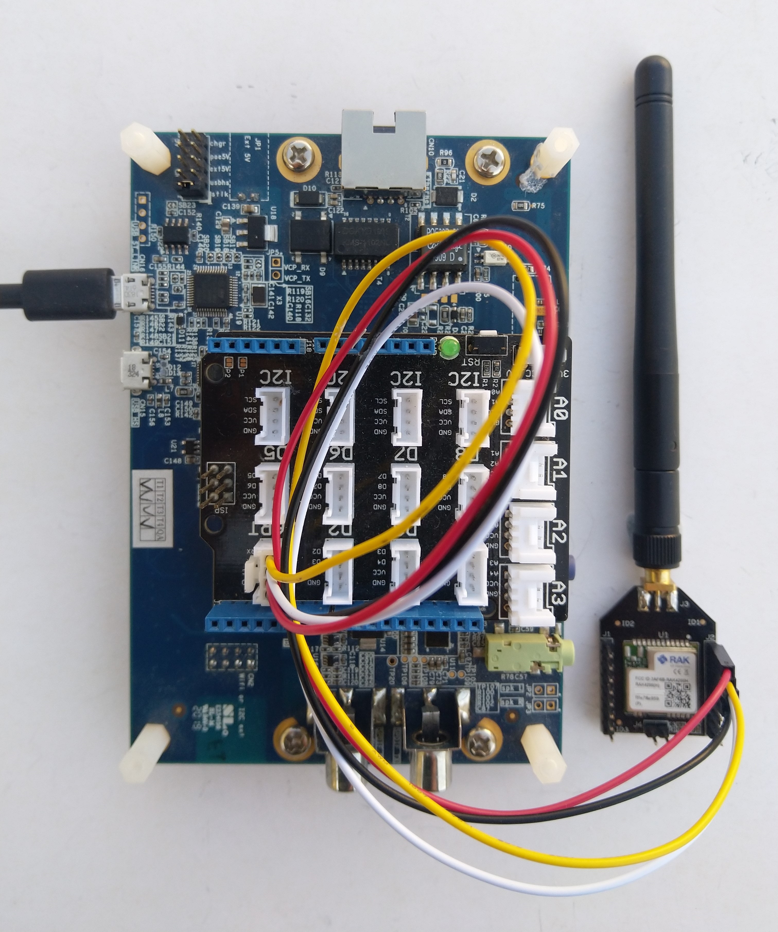
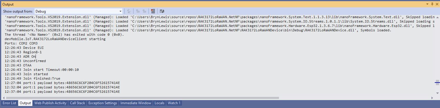
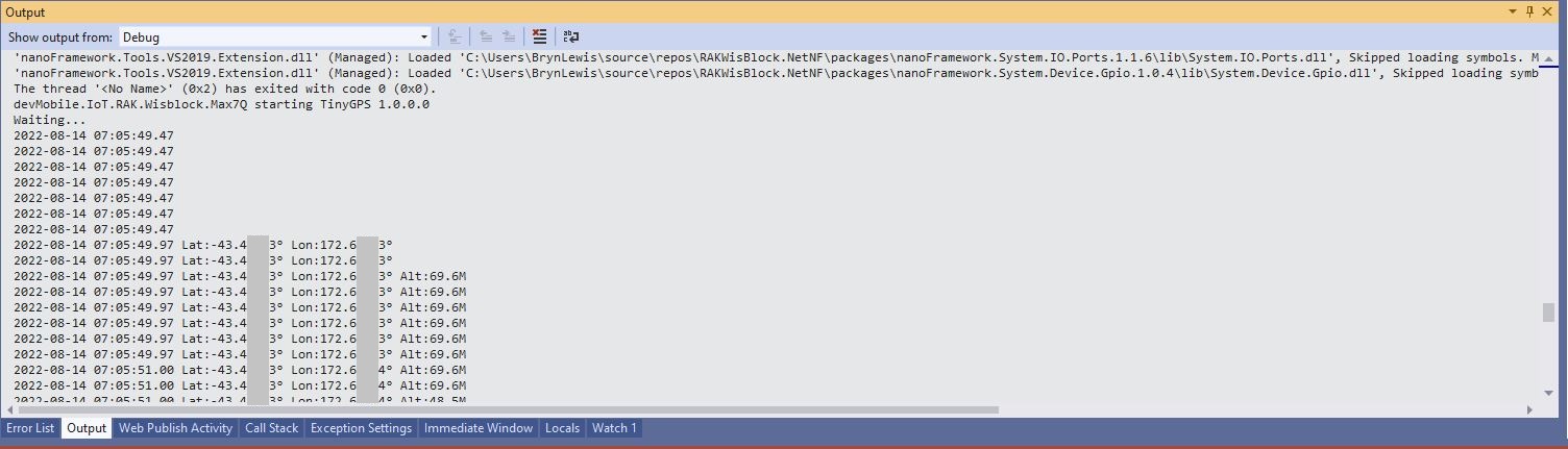
The RAKwireless RAK2305 WisBlock WiFi Interface Module module is based on an Expressif ESP32 processor which is supported by the .NET nanoFramework and I wanted try out it out with a RAK1910 GNSS GPS Location Module.

The RAK1910 application is based on the TinyGPSPlusNF library by MBoude which parses the NMEA 0183 sentences produced by the RAK1910.
//---------------------------------------------------------------------------------
// Copyright (c) August 2022, devMobile Software
//
// Licensed under the Apache License, Version 2.0 (the "License");
// you may not use this file except in compliance with the License.
// You may obtain a copy of the License at
//
// http://www.apache.org/licenses/LICENSE-2.0
//
// Unless required by applicable law or agreed to in writing, software
// distributed under the License is distributed on an "AS IS" BASIS,
// WITHOUT WARRANTIES OR CONDITIONS OF ANY KIND, either express or implied.
// See the License for the specific language governing permissions and
// limitations under the License.
//
// RAK Core WisBlock
// https://docs.rakwireless.com/Product-Categories/WisBlock/RAK11200
//
// RAK WisBlock Wireless
// https://docs.rakwireless.com/Product-Categories/WisBlock/RAK2305/Overview/
//
// RAK WisBlock Bases
// https://docs.rakwireless.com/Product-Categories/WisBlock/RAK5005-O
// https://docs.rakwireless.com/Product-Categories/WisBlock/RAK19001
//
// RAK WisBlock Sensor
// https://docs.rakwireless.com/Product-Categories/WisBlock/RAK1910
//
// Uses the library
// https://github.com/mboud/TinyGPSPlusNF
//
// Inspired by
// https://github.com/RAKWireless/WisBlock/tree/master/examples/common/sensors/RAK1910_GPS_UBLOX7
//
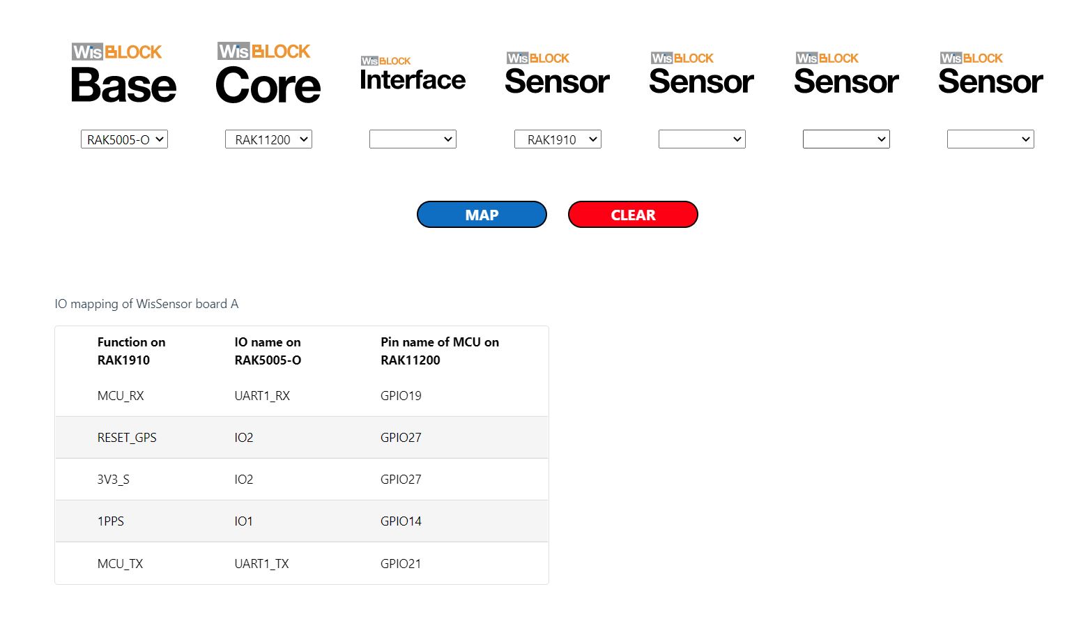
// Pins mapped with
// https://docs.rakwireless.com/Knowledge-Hub/Pin-Mapper/
//
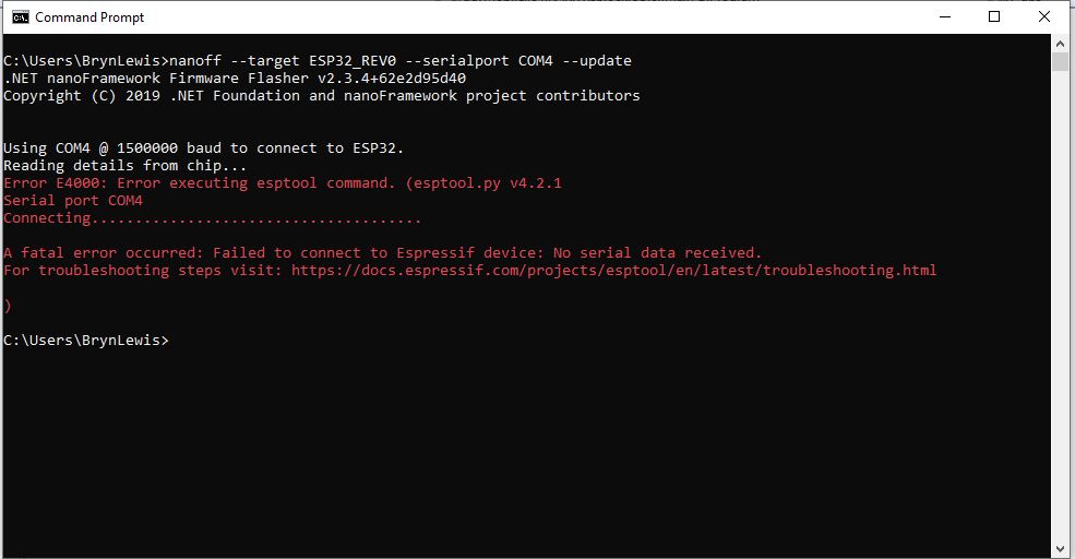
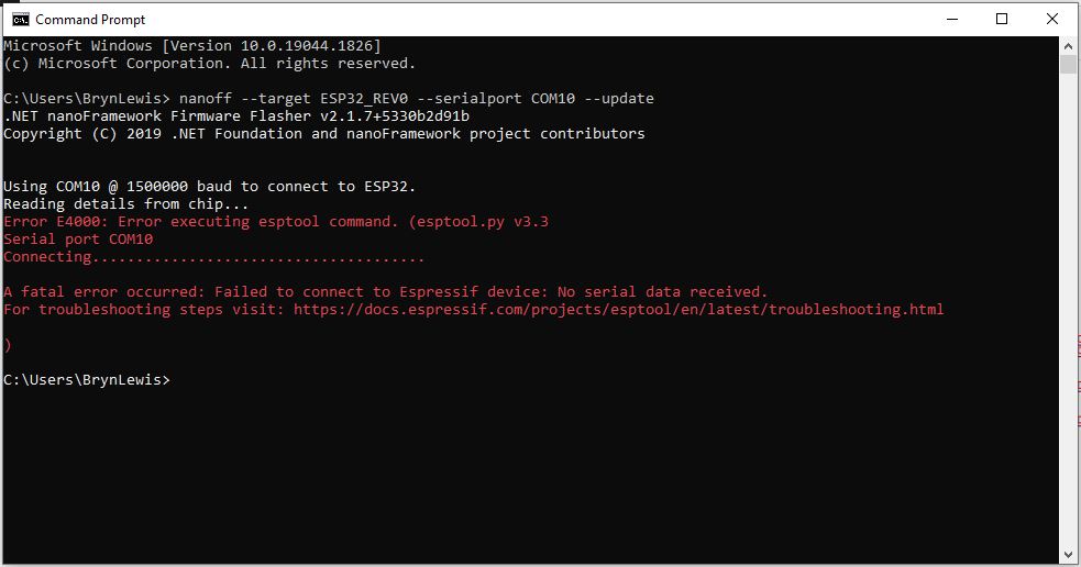
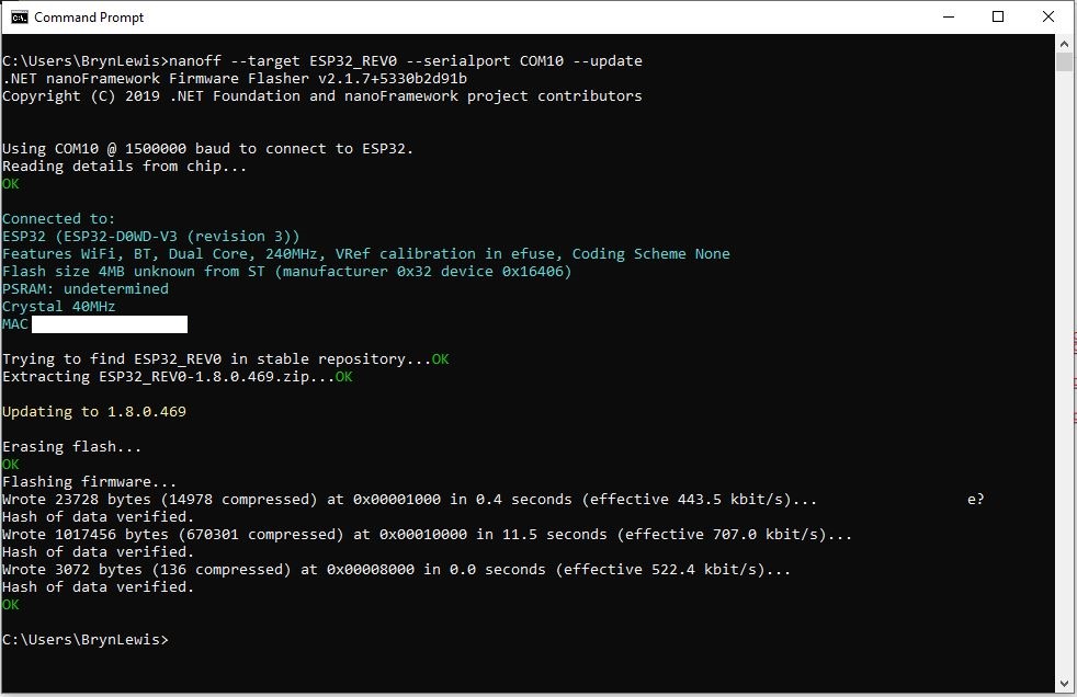
// Flash device with
// nanoff --target ESP32_REV0 --serialport COM16 --update
//
//---------------------------------------------------------------------------------
namespace devMobile.IoT.RAK.Wisblock.RAK1910
{
using System;
using System.Device.Gpio;
using System.Diagnostics;
using System.IO.Ports;
using System.Threading;
using nanoFramework.Hardware.Esp32;
using TinyGPSPlusNF;
public class Program
{
private static TinyGPSPlus _gps;
public static void Main()
{
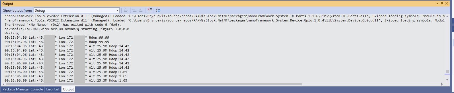
Debug.WriteLine($"devMobile.IoT.RAK.Wisblock.RAK1910 starting TinyGPS {TinyGPSPlus.LibraryVersion}");
try
{
#if RAK11200
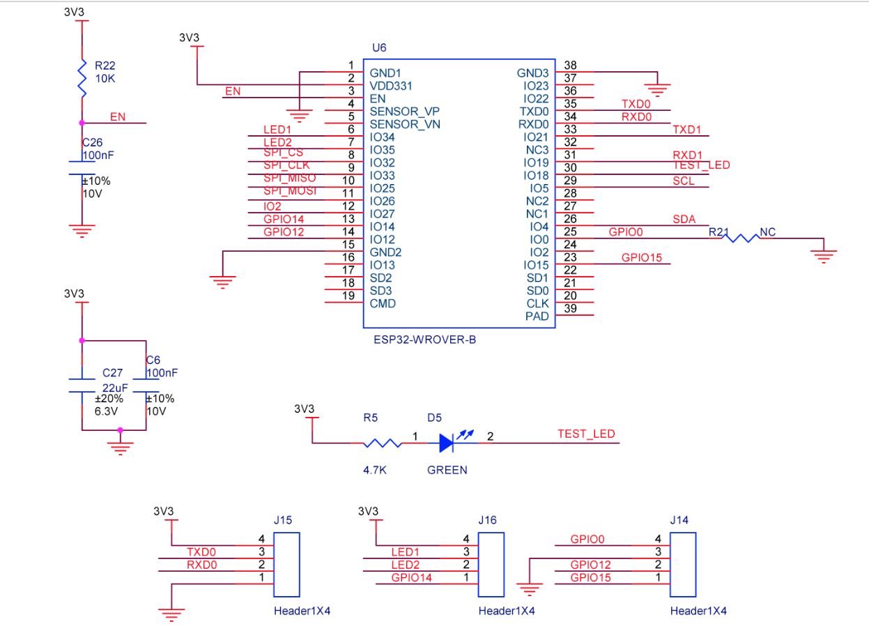
Configuration.SetPinFunction(Gpio.IO21, DeviceFunction.COM2_TX);
Configuration.SetPinFunction(Gpio.IO19, DeviceFunction.COM2_RX);
#endif
#if RAK2350
Configuration.SetPinFunction(Gpio.IO21, DeviceFunction.COM2_RX);
Configuration.SetPinFunction(Gpio.IO19, DeviceFunction.COM2_TX);
#endif
_gps = new TinyGPSPlus();
// UART1 with default Max7Q baudrate
SerialPort serialPort = new SerialPort("COM2", 9600);
serialPort.DataReceived += SerialDevice_DataReceived;
serialPort.Open();
serialPort.WatchChar = '\n';
// Enable the GPS module GPS 3V3_S/RESET_GPS - IO2 - GPIO27
GpioController gpioController = new GpioController();
GpioPin Gps3V3 = gpioController.OpenPin(Gpio.IO27, PinMode.Output);
Gps3V3.Write(PinValue.High);
Debug.WriteLine("Waiting...");
Thread.Sleep(Timeout.Infinite);
}
catch (Exception ex)
{
Debug.WriteLine($"UBlox MAX7Q initialisation failed {ex.Message}");
Thread.Sleep(Timeout.Infinite);
}
}
private static void SerialDevice_DataReceived(object sender, SerialDataReceivedEventArgs e)
{
// we only care if got EoL character
if (e.EventType != SerialData.WatchChar)
{
return;
}
SerialPort serialDevice = (SerialPort)sender;
string sentence = serialDevice.ReadExisting();
if (_gps.Encode(sentence))
{
if (_gps.Date.IsValid)
{
Debug.Write($"{_gps.Date.Year}-{_gps.Date.Month:D2}-{_gps.Date.Day:D2} ");
}
if (_gps.Time.IsValid)
{
Debug.Write($"{_gps.Time.Hour:D2}:{_gps.Time.Minute:D2}:{_gps.Time.Second:D2}.{_gps.Time.Centisecond:D2} ");
}
if (_gps.Location.IsValid)
{
Debug.Write($"Lat:{_gps.Location.Latitude.Degrees:F5}° Lon:{_gps.Location.Longitude.Degrees:F5}° ");
}
if (_gps.Altitude.IsValid)
{
Debug.Write($"Alt:{_gps.Altitude.Meters:F1}M ");
}
if (_gps.Location.IsValid)
{
Debug.Write($"Hdop:{_gps.Hdop.Value:F2}");
}
if (_gps.Date.IsValid || _gps.Time.IsValid || _gps.Location.IsValid || _gps.Altitude.IsValid)
{
Debug.WriteLine("");
}
}
}
}
}
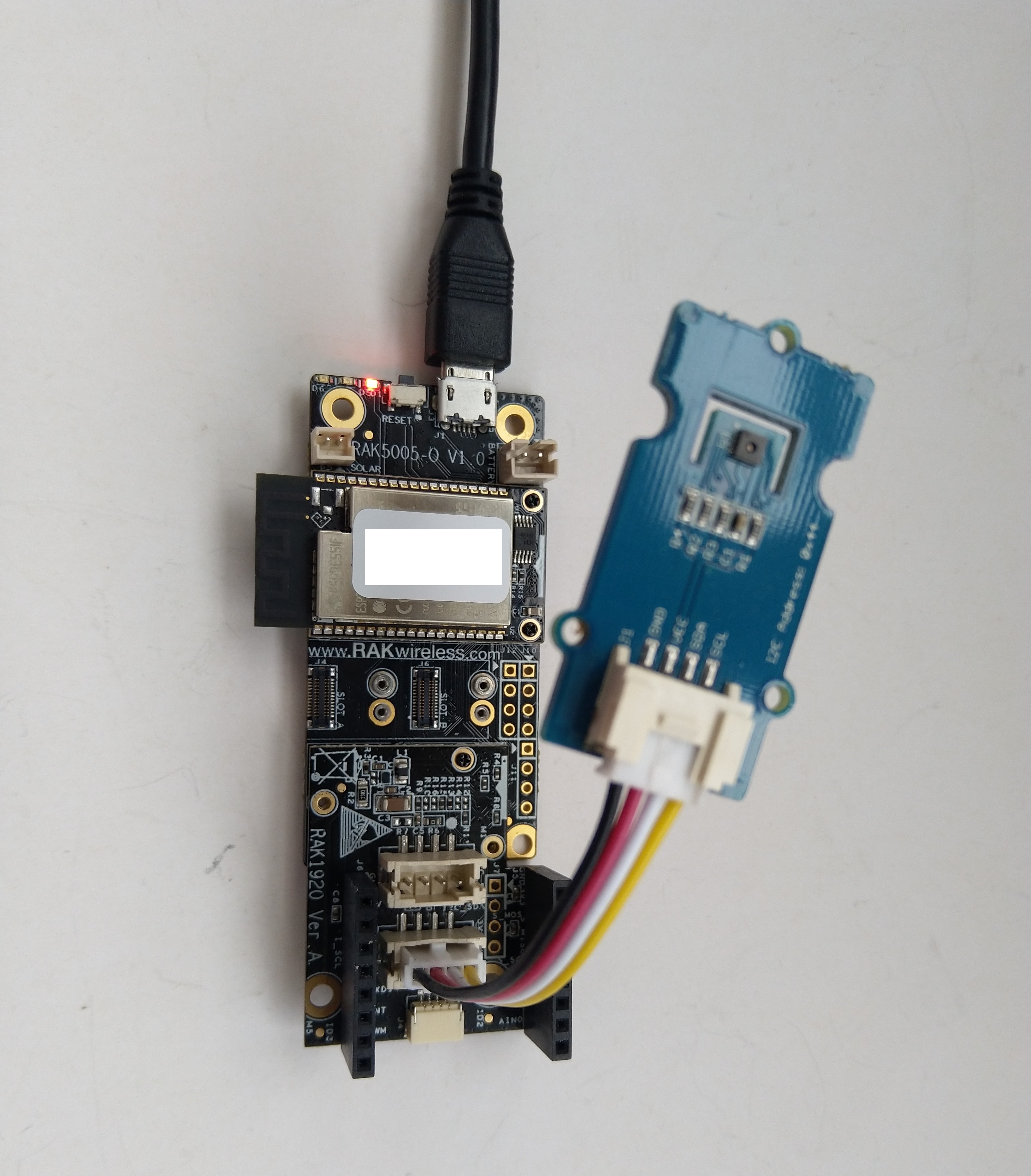
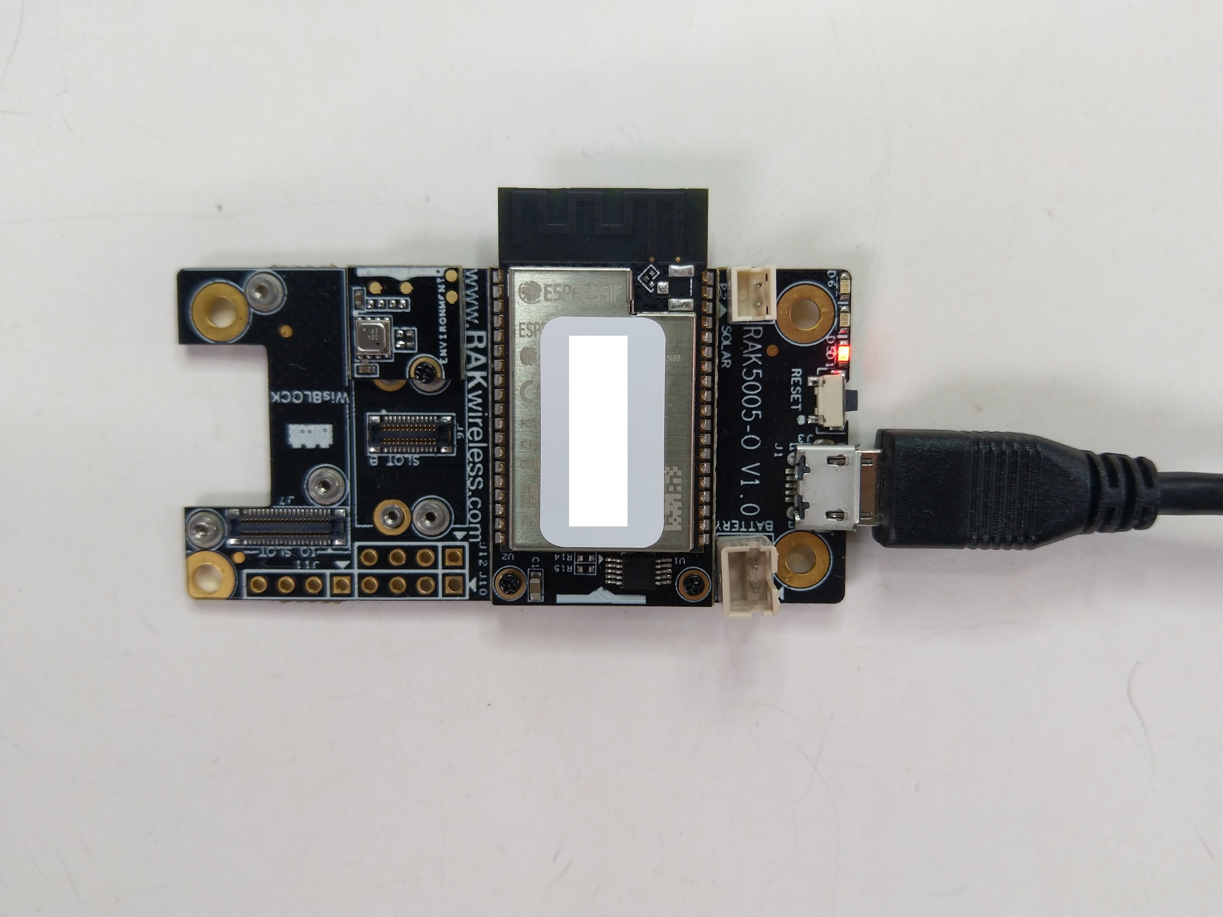
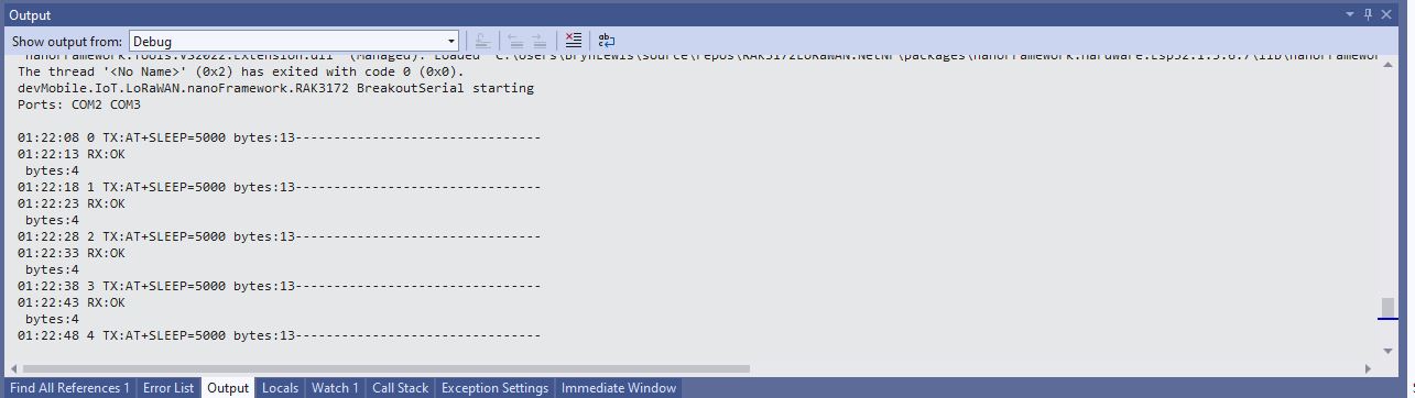
My RAK2305 WisBlock WiFi Interface Module, RAK1910, and RAK5005-O WisBlock Base Board configuration wasn’t supported by the RAK WinBlock Pin Mapper(AUG 2022) tool.
After some experimentation I found that serial port TX/RX lines had to be reversed because both devices would normally be connected to a WisBlock core module.