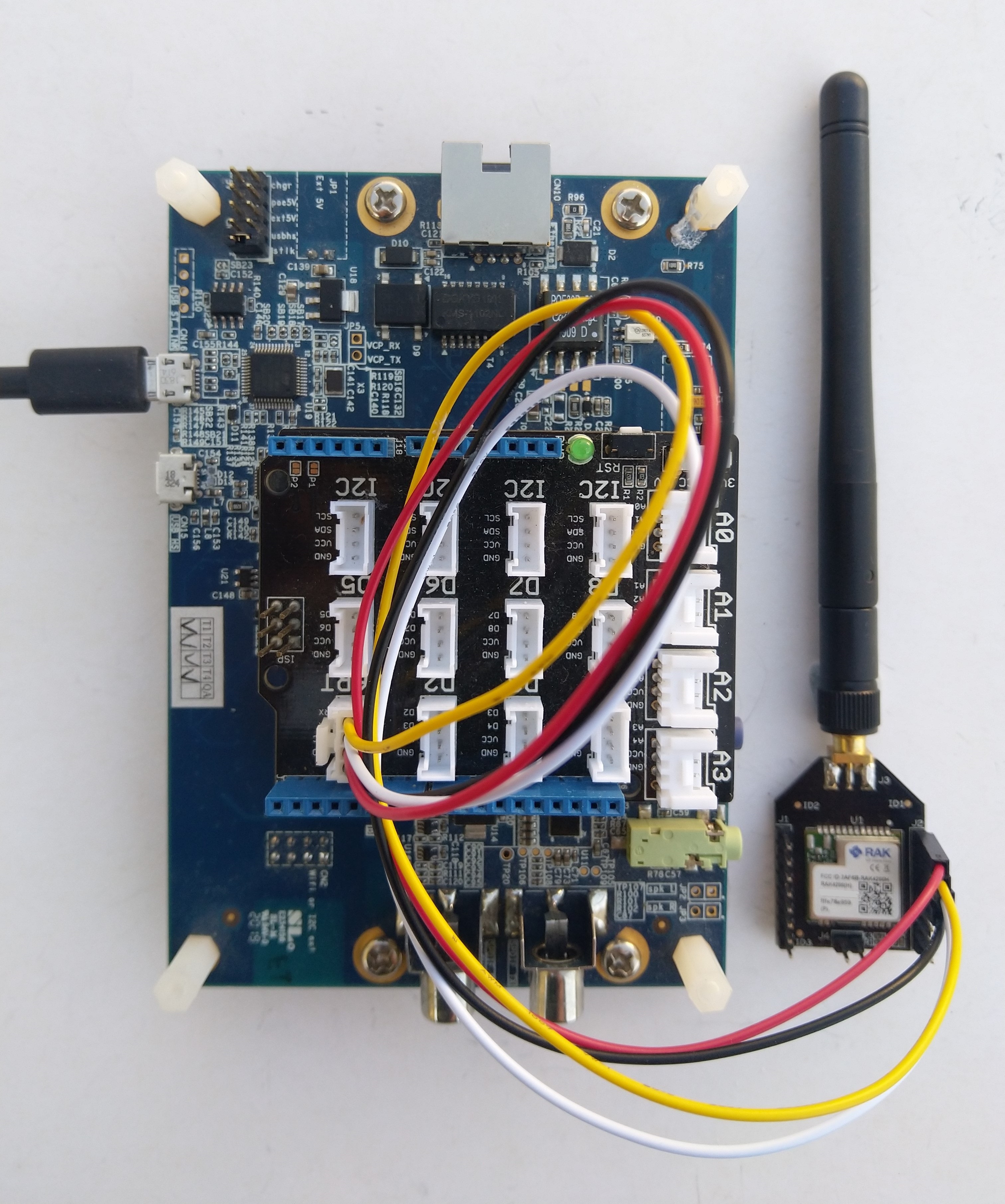
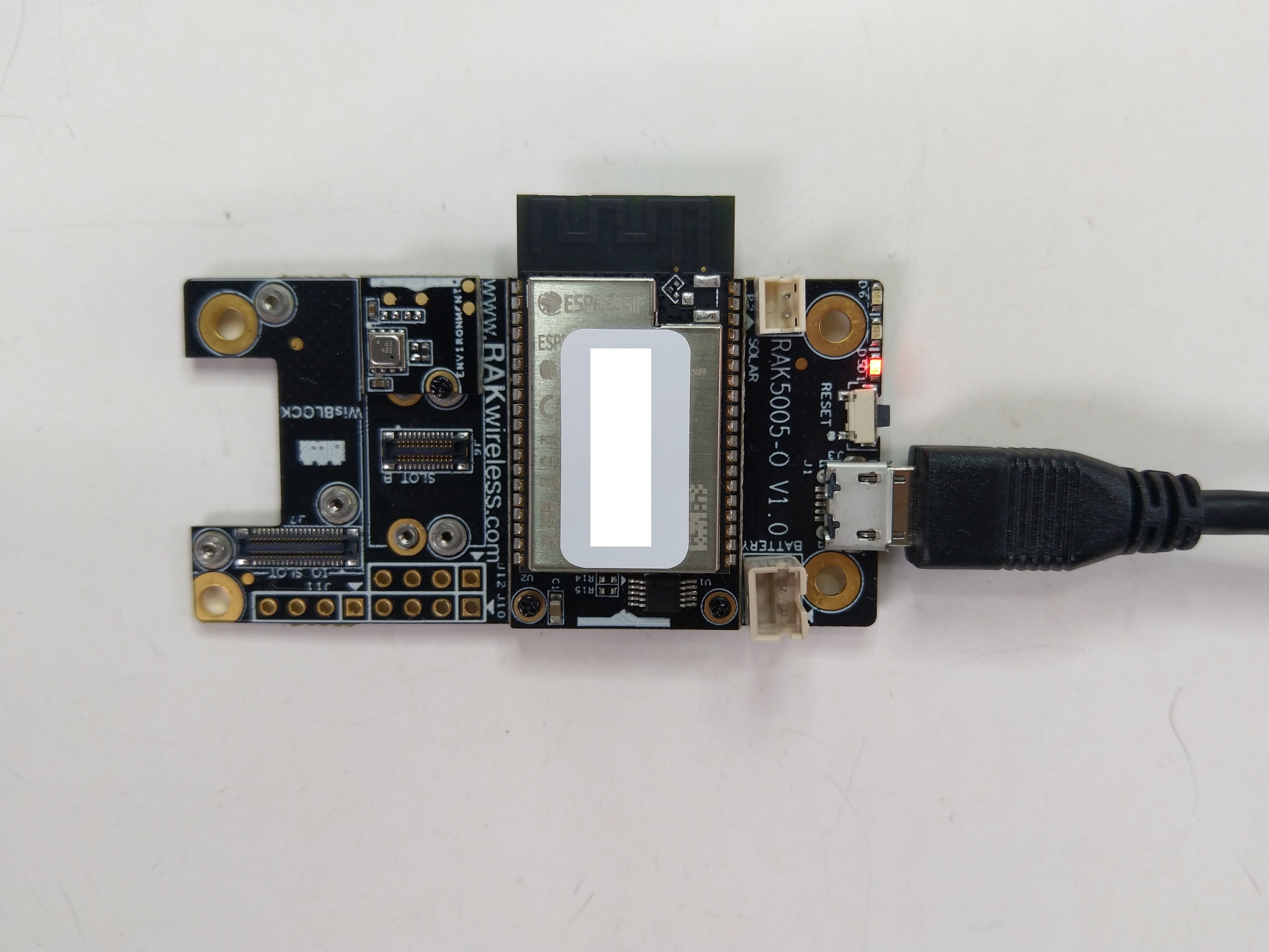
The RAKwireless RAK11200 WisBlock WiFi Module module is based on an Expressif ESP32 processor which is supported by the .NET nanoFramework. The first step was to mount the RAK11200 on a RAK5005 WisBlock Base Board to get Universal Serial Bus(USB) connectivity.
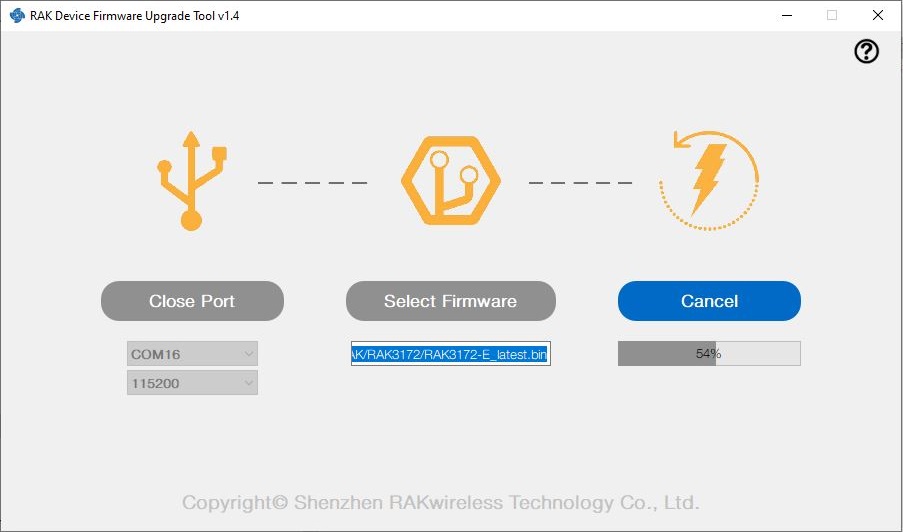
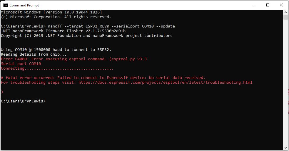
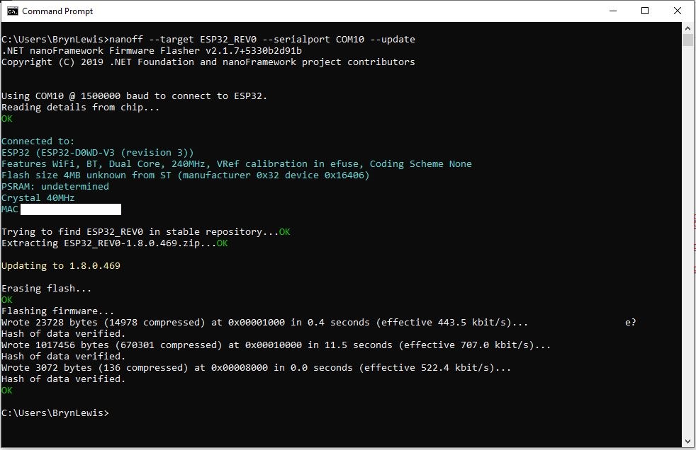
My first attempt “flash” the RAK11200 with the nano Firmware Flasher(nanoff) failed badly
The RAK11200 documentation described how to upload software developed with the Arduino tools by putting the ESP32 into “bootloader mode” by connecting the BOOT0 and GND pins, then pressing the reset button.

After some “trial and error” the download process worked pretty reliably…
The first step with any embedded development project is to flash a Light Emitting Diode(LED)….

The RAK11200 has two LEDs, a blue attached to IO02 and a green one attached to IO12.
//
// Copyright (c) .NET Foundation and Contributors
// See LICENSE file in the project root for full license information.
//
//
using System;
using System.Device.Gpio;
using System.Threading;
using nanoFramework.Hardware.Esp32;

namespace Blinky
{
   public class Program
   {
      private static GpioController s_GpioController;
      public static void Main()
      {
         s_GpioController = new GpioController();

         // pick a board, uncomment one line for GpioPin; default is STM32F769I_DISCO

         // DISCOVERY4: PD15 is LED6
         //GpioPin led = s_GpioController.OpenPin(PinNumber('D', 15), PinMode.Output);

         // ESP32 DevKit: 4 is a valid GPIO pin in, some boards like Xiuxin ESP32 may require GPIO Pin 2 instead.
         //GpioPin led = s_GpioController.OpenPin(4, PinMode.Output);

         // FEATHER S2:
         //GpioPin led = s_GpioController.OpenPin(13, PinMode.Output);

         // F429I_DISCO: PG14 is LEDLD4
         //GpioPin led = s_GpioController.OpenPin(PinNumber('G', 14), PinMode.Output);

         // NETDUINO 3 Wifi: A10 is LED onboard blue
         //GpioPin led = s_GpioController.OpenPin(PinNumber('A', 10), PinMode.Output);

         // QUAIL: PE15 is LED1
         //GpioPin led = s_GpioController.OpenPin(PinNumber('E', 15), PinMode.Output);

         // STM32F091RC: PA5 is LED_GREEN
         //GpioPin led = s_GpioController.OpenPin(PinNumber('A', 5), PinMode.Output);

         // STM32F746_NUCLEO: PB75 is LED2
         //GpioPin led = s_GpioController.OpenPin(PinNumber('B', 7), PinMode.Output);

         //STM32F769I_DISCO: PJ5 is LD2
         //GpioPin led = s_GpioController.OpenPin(PinNumber('J', 5), PinMode.Output);

         // ST_B_L475E_IOT01A: PB14 is LD2
         //GpioPin led = s_GpioController.OpenPin(PinNumber('B', 14), PinMode.Output);

         // STM32L072Z_LRWAN1: PA5 is LD2
         //GpioPin led = s_GpioController.OpenPin(PinNumber('A', 5), PinMode.Output);

         // TI CC13x2 Launchpad: DIO_07 it's the green LED
         //GpioPin led = s_GpioController.OpenPin(7, PinMode.Output);

         // TI CC13x2 Launchpad: DIO_06 it's the red LED
         //GpioPin led = s_GpioController.OpenPin(6, PinMode.Output);

         // ULX3S FPGA board: for the red D22 LED from the ESP32-WROOM32, GPIO5
         //GpioPin led = s_GpioController.OpenPin(5, PinMode.Output);

         // Silabs SLSTK3701A: LED1 PH14 is LLED1
         //GpioPin led = s_GpioController.OpenPin(PinNumber('H', 14), PinMode.Output);

         // RAK11200 on RAK5005
         //GpioPin led = s_GpioController.OpenPin(Gpio.IO12, PinMode.Output); // LED1 Green
         //GpioPin led = s_GpioController.OpenPin(Gpio.IO02, PinMode.Output); // LED2 Blue

         // RAK11200 on RAK19001 needs battery connected or power switch in rechargeable position.
         //GpioPin led = s_GpioController.OpenPin(Gpio.IO12, PinMode.Output); // LED1 Green
         //GpioPin led = s_GpioController.OpenPin(Gpio.IO02, PinMode.Output); // LED2 Blue

         // RAK2305
         //GpioPin led = s_GpioController.OpenPin(Gpio.IO18, PinMode.Output); // LED Green (Test LED) on device

         // RAK2305 On 5005 throws exceptions
         //GpioPin led = s_GpioController.OpenPin(Gpio.IO34, PinMode.Output); // LED1 Green
         //GpioPin led = s_GpioController.OpenPin(Gpio.IO35, PinMode.Output); // LED2 Blue

         // RAK2305 On 17001 throws exceptions
         //GpioPin led = s_GpioController.OpenPin(Gpio.IO34, PinMode.Output); // LED1 Green
         //GpioPin led = s_GpioController.OpenPin(Gpio.IO35, PinMode.Output); // LED2 Blue

         led.Write(PinValue.Low);

         while (true)
         {
            led.Toggle();
            Thread.Sleep(125);
            led.Toggle();
            Thread.Sleep(125);
            led.Toggle();
            Thread.Sleep(125);
            led.Toggle();
            Thread.Sleep(525);
         }
      }

      static int PinNumber(char port, byte pin)
      {
         if (port < 'A' || port > 'J')
            throw new ArgumentException();

         return ((port - 'A') * 16) + pin;
      }
   }
}
I added the RAK11200 configuration to my version of the nanoFramework Blinky sample and could reliably flash either of the LEDs.