Azure Event Hub Updates from a NetMF Device

I had read about how Azure Event Hubs supported both Advanced Message Queuing Protocol(AMQP) & Hypertext Transfer Protocol (HTTP) access and was keen to see how easy the REST API was to use from a .Net Microframework (NetMF) device.

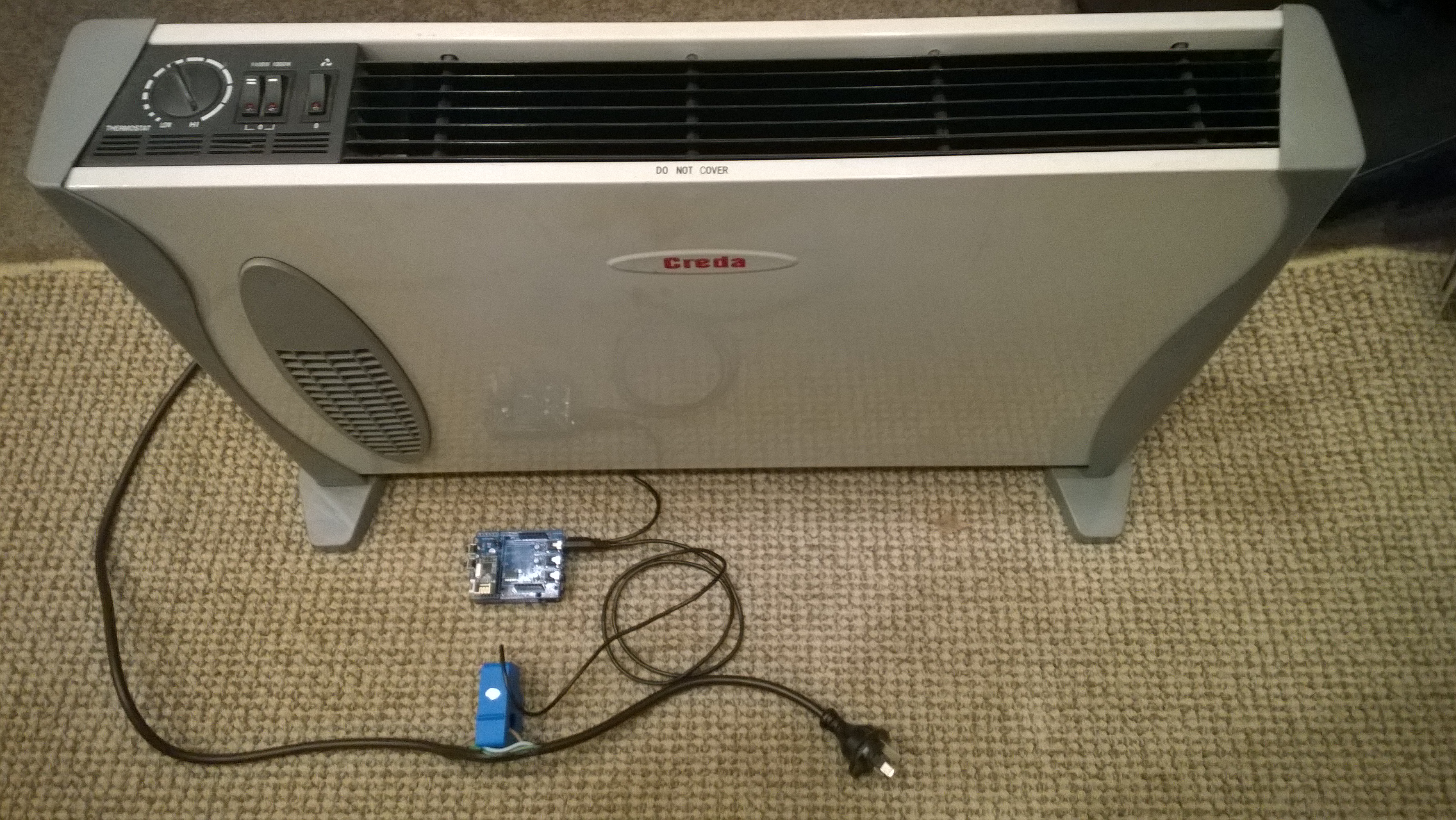
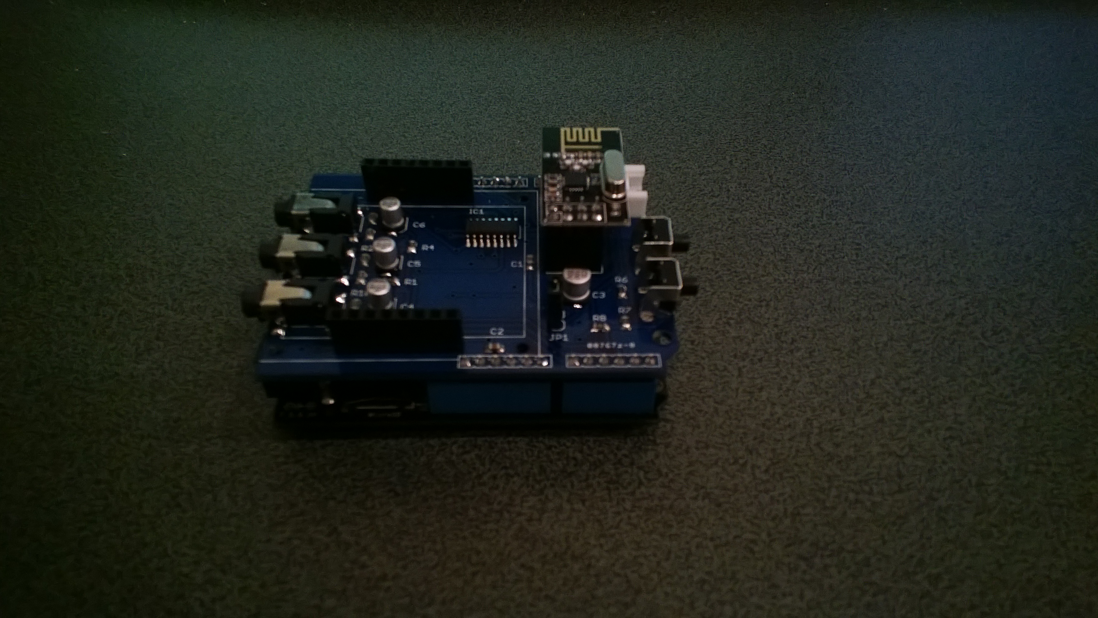
My initial concept was an exercise monitoring system with a Global Positioning System (GPS) unit and a pulse oximeter connected to a FEZ Spider device. My posting GPS Tracker Azure Service Bus has more info about GPS Drivers  and Azure Service Bus connectivity.

FEZ Spider, GPS and PulseOximeter

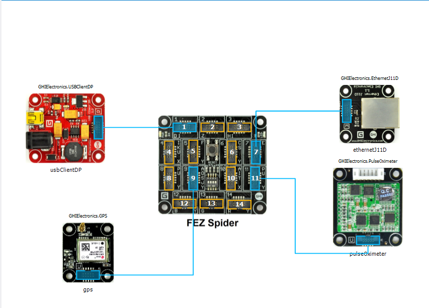
Fez spider and sensors for exercise monitoring device

The software was inspired by the Service Bus Event Hubs Getting started, Scale Out Event Processing with Event Hubs,Service Bus Event Hubs Large Scale Secure Publishing and OBD Recorder for .Net Micro Framework with ServiceBus, AMQP (for IoT) samples. I created an Event Hub and associated device access keys and fired up Service Bus Explorer so I could monitor and tweak the configuration.

I started by porting the REST API SendMessage implementation of Service Bus Event Hubs Large Scale Secure Publishing sample to NetMF. My approach was to get the application into my local source control and then cut ‘n’ paste the code into a NetMF project and see what breaks. I then modified the code over several iterations so it ran on both the desktop and NetMF clients.

The next step was to download the HTTPS certificates and add them to the project as resources so the requests could be secured. See this post for more detail.

For the connection to be secured you need to set the local time (so the certificate valid to/from can be checked) and load the certificates so they can be attached to the HTTP requests

void ProgramStarted()
{
   ...
   Microsoft.SPOT.Hardware.Utility.SetLocalTime(NtpClient.GetNetworkTime());
   caCerts = new X509Certificate[] { new X509Certificate(Resources.GetBytes(Resources.BinaryResources.Baltimore)) };

I used the Network Time Protocol (NTP) library from the OBD Recorder for .Net Micro Framework sample to get the current time.

The Service Bus Event Hubs Large Scale Secure Publishing uses an asynchronous HTTP request which is not available on the NetMF platform. So I had to replace it with a synchronous version.

static void EventHubSendMessage(string eventHubAddressHttps, string token, string messageBody)
{
   try
   {
      HttpWebRequest request = (HttpWebRequest)HttpWebRequest.Create(eventHubAddressHttps + "/messages" + "?timeout=60" + ApiVersion);
      {
         ...
         request.Headers.Add("Authorization", token);
         request.Headers.Add("ContentType", "application/atom+xml;type=entry;charset=utf-8");
         byte[] buffer = Encoding.UTF8.GetBytes(messageBody);
         request.ContentLength = buffer.Length;

         // request body
         using (Stream stream = request.GetRequestStream())
         {
            stream.Write(buffer, 0, buffer.Length);
         }
         using (HttpWebResponse response = (HttpWebResponse)request.GetResponse())
         {
            Debug.Print("HTTP Status:" + response.StatusCode + " : " + response.StatusDescription);
         }
      }
   }
   catch (WebException we)
   {
      Debug.Print(we.Message);
   }
}

The code to generate the SAS Token also required some modification as string.format, timespan, and SHA256 functionality are not natively available on the .NetMF platform. The GetExpiry, and SHA256 implementations were part of the OBD Recorder for .Net Micro Framework sample.

static string CreateSasToken(string uri, string keyName, string key)
{
   // Set token lifetime to 20 minutes. When supplying a device with a token, you might want to use a longer expiration time.
   uint tokenExpirationTime = GetExpiry(20 * 60);

   string stringToSign = HttpUtility.UrlEncode(uri) + "\n" + tokenExpirationTime;
   var hmac = SHA.computeHMAC_SHA256(Encoding.UTF8.GetBytes(key), Encoding.UTF8.GetBytes(stringToSign));

   string signature = Convert.ToBase64String(hmac);
   signature = Base64NetMf42ToRfc4648(signature);

   string token = "SharedAccessSignature sr=" + HttpUtility.UrlEncode(uri) + "&sig=" + HttpUtility.UrlEncode(signature) + "&se=" + tokenExpirationTime.ToString() + "&skn=" + keyName;
   return token;
}

static uint GetExpiry(uint tokenLifetimeInSeconds)
{
   const long ticksPerSecond = 1000000000 / 100; // 1 tick = 100 nano seconds</code>

   DateTime origin = new DateTime(1970, 1, 1, 0, 0, 0, 0);
   TimeSpan diff = DateTime.Now.ToUniversalTime() - origin;

   return ((uint)(diff.Ticks / ticksPerSecond)) + tokenLifetimeInSeconds;
}

private static string Base64NetMf42ToRfc4648(string base64netMf)
{
   var base64Rfc = string.Empty;
   for (var i = 0; i < base64netMf.Length; i++)
   {
      if (base64netMf[i] == '!')
      {
         base64Rfc += '+';
      }
      else if (base64netMf[i] == '*')
      {
         base64Rfc += '/';
      }
      else
      {
         base64Rfc += base64netMf[i];
      }
   }
return base64Rfc;
}

The HttpUtility class came from the OBD Recorder for .Net Micro Framework sample. The Base64NetMf42ToRfc4648 functionality is still necessary on NetMF 4.3.

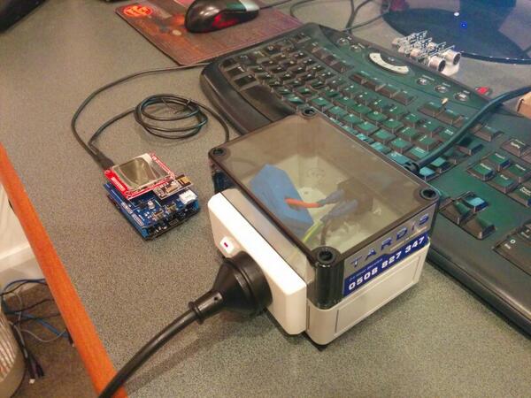
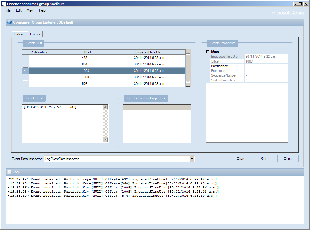
After a couple of hours I had data upload working.(No GPS data as the device was running on my desk where GPS coverage is poor)

ServiceBusExplorerEventHub

TechEd 2014 Auckland Presentation online

My TechEd INO204 presentation in now online at on MSDN Channel 9.

INO204  The Things of the Internet of Things
Speaker Rating
3.54 / 4  84.7%

Overall Rating
3.44 / 4 81.29%

The presenters desk had my laptop, document camera, 2 Fez spiders, 9 Netduinos, 2 devDuinos and an Arduino Uno R3 device so it was pretty busy.

TechEdPresentersDesk[1]

While preparing for the presentation I had some problems with the EMG stick on sensors

EMGStickOnPadMarks[1]

GPS Tracker Azure Service Bus

After a break from the GPSTracker samples I dug out my FEZ Spider devices, upgraded them to .NetMF 4.3 and downloaded the discontinued module drivers so my SeeedStudio GPS would work.


GPS Tracker using FEZ Spider mainboard

GPS Tracker built using FEZ Spider mainboard

I updated the root certificates in the Microsoft.ServiceBus.Micro resources to the current “Baltimore CyberTrust Root” ones using the process described here

The code is based on the OBD Recorder for .Net Micro Framework with ServiceBus, AMQP (for IoT)

The GPS is initialised with handlers for valid & invalid positions.

gpsStatusLED.TurnRed();
gps.InvalidPositionReceived += gps_InvalidPositionReceived;
gps.PositionReceived += gps_PositionReceived;

void gps_InvalidPositionReceived(GPS sender, EventArgs e)
{
   gpsStatusLED.TurnRed();
}

<code>void gps_PositionReceived(GPS sender, GPS.Position e)
{
   gpsStatusLED.TurnGreen();
}

Once the network interface has an IP address, the time on the FEZ Spider is set (so the certificate from and until times can be checked) and then the ServiceBus connection is initialised

IPAddress ip = IPAddress.GetDefaultLocalAddress();

// Setup the device time
if (ip != IPAddress.Any)
{
   ....
   DateTime networkTime = NtpClient.GetNetworkTime();
   Microsoft.SPOT.Hardware.Utility.SetLocalTime(networkTime);
...

   SASTokenProvider tp = new SASTokenProvider("device", "YourTopSecretKey=");
   messagingClient = new MessagingClient(new Uri(@"https://YourEndpoint.servicebus.windows.net/YourQueueName"), tp);</code>

   Once the GPS returns a valid position every so often a message is sent to the service bus queue

   SimpleMessage message = new SimpleMessage()
   {
      BrokerProperties = { { "SessionId", Guid.NewGuid().ToString()}, { "Label", "NMEAPositionData" } },
      Properties =
      {
         { "Latitude", gps.LastPosition.Latitude.ToString("F4") },
         { "Longitude", gps.LastPosition.Longitude.ToString("F4") },
      },
   };
   try
   {
      Debug.Print("Message send");
      messagingClient.Send(message);
      Debug.Print("Message sent OK");
   }
   catch (Exception ex)
   {
      Debug.Print(ex.Message);
   }

The send appeared to be quite slow (even on my home LAN so some further investigation is required)

6462mSec
6399mSec
6471mSec
6346mSec
7403mSec

6325mSec
6188mSec
6426mSec
6493mSec
6555mSec

Average 6506mSec

Energy Monitor Shield Nokia 5100 Display

The Energy Monitor Shield is supplied with a Nokia 5110 LCD for displaying instantaneous power consumption etc. There is an excellent Netduino driver for the Nokia 5100 display by omar, and with a few modifications this works with the Energy Monitor Shield. I removed the backlight support and made a few other simple modifications.

Nokia_5110 Lcd = new Nokia_5110(Pins.GPIO_PIN_D3, Pins.GPIO_PIN_D6, Pins.GPIO_PIN_D5);

while (true)
{
   Lcd.Clear();
   Lcd.DrawString(0, 0, DateTime.Now.ToString("HH:mm:ss"), true);
   Lcd.DrawString(0, 1, DateTime.Now.ToString("HH:mm:ss"), true);
   Lcd.DrawString(0, 2, DateTime.Now.ToString("HH:mm:ss"), true);
   Lcd.Refresh();
   Thread.Sleep(500)
}

Netduino Nokia 5110 driver

Energy Monitor Shield Noise Reduction

In a couple of previous posts the noise on the Netduino AnalogInput and the impact of this on the RMS current measurement was discussed. I trialled two versions of the code to see if my approach worked. Both versions used the initial calibration phase to measure the maximum and minimum values of the noise.

int valueSum = 0;
int valueNoiseMinimum = int.MaxValue;
int valueNoiseMaximum = int.MinValue;
int valueSumSqr = 0;
int offset;
AnalogInput x1 = new AnalogInput(Cpu.AnalogChannel.ANALOG_0);

// Calculate the sum for offset for first run
for (int i = 0; i &lt; SampleCount; i++)
{
  int value = x1.ReadRaw();
  valueSum = valueSum + value;

   if (value &lt; valueNoiseMinimum)
   {
      valueNoiseMinimum = value;
   }
   if (value &gt; valueNoiseMaximum)
   {
      valueNoiseMaximum = value;
   }
}

offset = valueSum / SampleCount;
valueNoiseMinimum -= offset;
valueNoiseMaximum -= offset;

The first version used only the initial offset

Stopwatch stopwatch = Stopwatch.StartNew();
stopwatch.Start();

for (int i = 0; i < SampleCount; i++)
{
   int value = x1.ReadRaw();
   value -= offset;

   if ((value &gt; valueNoiseMaximum) || (value &lt; valueNoiseMinimum))
   {
   valueSumSqr += (value * value);
   }
}
stopwatch.Stop();

RMS 42.2729 RMS Current 3.4A RMS Power 775W Duration = 3301 mSec 30293/sec
RMS 42.2137 RMS Current 3.4A RMS Power 774W Duration = 3302 mSec 30284/sec
RMS 42.2374 RMS Current 3.4A RMS Power 775W Duration = 3302 mSec 30284/sec
RMS 42.1307 RMS Current 3.4A RMS Power 773W Duration = 3302 mSec 30284/sec
RMS 42.1189 RMS Current 3.4A RMS Power 773W Duration = 3302 mSec 30284/sec
RMS 42.1307 RMS Current 3.4A RMS Power 773W Duration = 3302 mSec 30284/sec
RMS 42.1070 RMS Current 3.4A RMS Power 772W Duration = 3302 mSec 30284/sec
RMS 42.1189 RMS Current 3.4A RMS Power 773W Duration = 3302 mSec 30284/sec
RMS 42.1426 RMS Current 3.4A RMS Power 773W Duration = 3303 mSec 30275/sec

The second version updated the offset every iteration

Stopwatch stopwatch = Stopwatch.StartNew();
stopwatch.Start();

for (int i = 0; i &lt; SampleCount; i++)
{
   int value = x1.ReadRaw();
   valueSum += value;
   value -= offset;

   if ((value &gt; valueNoiseMaximum) || (value &lt; valueNoiseMinimum))
   {
      valueSumSqr += (value * value);
   }
}
stopwatch.Stop();
offset = valueSum / SampleCount;

This was slightly slower due to the extra addition operation in the sampling loop

RMS 41.5933 RMS Current 3.3A RMS Power 763W Duration = 3537 mSec 28272/sec
RMS 41.6653 RMS Current 3.3A RMS Power 764W Duration = 3541 mSec 28240/sec
RMS 41.6053 RMS Current 3.3A RMS Power 763W Duration = 3538 mSec 28264/sec
RMS 41.5572 RMS Current 3.3A RMS Power 762W Duration = 3537 mSec 28272/sec
RMS 41.5331 RMS Current 3.3A RMS Power 762W Duration = 3537 mSec 28272/sec
RMS 41.4970 RMS Current 3.3A RMS Power 761W Duration = 3540 mSec 28248/sec
RMS 41.4849 RMS Current 3.3A RMS Power 761W Duration = 3538 mSec 28264/sec
RMS 41.4849 RMS Current 3.3A RMS Power 761W Duration = 3516 mSec 28441/sec

At 28K4 samples per second the self adjusting RMS calculation is sampling the 50Hz waveform much more frequently than required.

Energy Monitor Shield Sensor Box by Tardis

My initial way of connecting the current sensor for the Energy Monitor Shield was not really suitable for CodeClub. Carefully cutting the insulation with a craft knife and gently pulling out the phase wire could end really badly.

Image

I approached a local company Tardis Communications and they made Code Club these neat enclosures which ensure the students can’t come into contact with any live connections.

Image

Canterbury Software Cluster Internet of Things Presentation

For my presentation last week I prepared a sample xively and Netduino based application to illustrate what could be built with off the shelf kit. I built a wireless home monitoring system which had two energy consumption monitoring devices and a dual temperature sensor device. These devices uploaded their data using MQTT to xively in close to real time. Prices as at May 2014

The devices connected to the internet via a gateway.

Image

The software running on the Netduino was built using the NetMF library from KittyHawkMQ and the nRF24L01+ library from codeplex

Testing the solar powered temperature sensor monitoring my kitchen fridge. The fridge was 4° and the freezer was -18°

Image

The software was based on the nRF24L01library on codeplex,  Brad’s One-Wire and DS18B20 library with fixes from here.

Testing the power consumption monitor devices, with my “modified” power lead.

Image

The software was based on the approach in the Arduino code of the emon libraries from the Open Energy Monitor project which I’ll discuss in more detail in a future post.

Energy Monitor Shield Current Sensor

The energy monitor shield has three current sensor inputs (A0 thru A2) which have a voltage divider to provide a reference offset voltage for the analog inputs on the Netduino. The reference offset voltage with a 5V supply was 2.5V which meant on a 3.3V device the range of the sensors (1V for 30 Amps) would be compromised.

In a previous post I modified the shield by replacing a resistor but there appears to be an easier modification. While looking at the schematic and the shield I realised that cutting off the 5V pin and connecting the 3.3V pin and 5V pin together would make all the analog inputs use the 3.3V rail.

Energy Shield with modifications for 3.3V operation

Energy Shield with modifications for 3.3V operation

It would be good if the designers of the shield would consider putting a switch or jumpers on the device to allow 3V3 or 5V operation.

public class Program
{
public static void Main()
{
AnalogInput buttons = new AnalogInput(Cpu.AnalogChannel.ANALOG_0);

while (true)
{
Debug.Print(buttons.Read().ToString(“F2”));

Thread.Sleep(250);
}
}
}

Energy Monitor Shield Buttons

The two buttons on the energy monitor shield are connected to the analog input A3 via a voltage divider. The shield appears to be designed for 5V devices as the input for the voltage divider is connected to VCC which is 5V. Netduinos and some Arduinos are 3.3V devices and this approach won’t work on these devices.

public static void Main()
{
AnalogInput buttons = new AnalogInput(Cpu.AnalogChannel.ANALOG_3);


while (true)
{
Debug.Print(buttons.Read().ToString("F2"));
Thread.Sleep(250);
}
}

The return value of the AnalogOutput with no button pressed was 1.0, SW1 pressed 1.0 and with SW2 pressed 0.93.

To work around this issue I modified the shield so the input voltage to the voltage divider is 3.3V. With my modified shield the return value of the AnalogOutput with no button pressed was 0.87, SW1 pressed 0.83 and with SW2 pressed 0.67. [Edit-see next post with easier modification]

To change the input voltage of the voltage divider I removed R8(circled) and replaced it with a 1K resistor connected to 3.3V.

Energy Shield with Button modifications

Energy Shield with Button modifications


Energy Monitor Shield nRF24L01+

The nRF24L01 functionality looked like a good place to start so I had a look at the documentation. The interface for connecting the nRF24L01+ module was specified as

D11 – MOSI
D12 – MISO
D13 – SCK
D8 – RF_CE
D7 – RF_CSN
D2 – RF_IRQ

I have used the Nordic nRF240L1+ .Net Micro Framework Driver on a couple of other projects but initially struggled to get it working with this configuration. After looking at the pin outs of the nRF24L01+ and the Energy Monitor Shield schematic I think the CSN & CE are reversed.(as at March 2014).

This code works and was adapted from the sample application provided with the driver on codeplex

public class nRF240l1Module
{
private const byte channel = 10;
private readonly OutputPort _led = new OutputPort(Pins.ONBOARD_LED, false);
private readonly NRF24L01Plus _module;
private Timer _timer;
private byte _token;

private readonly byte[] _myAddress = Encoding.UTF8.GetBytes(“NetP1”);
//private readonly byte[] _myAddress = Encoding.UTF8.GetBytes(“NetP2”);
private readonly byte[] _otherBoard = Encoding.UTF8.GetBytes(“NetP2”);
//private readonly byte[] _otherBoard = Encoding.UTF8.GetBytes(“NetP1”);

public nRF240l1Module()
{
_module = new NRF24L01Plus();
}

public void Run()
{
_module.OnDataReceived += OnReceive;
_module.OnTransmitFailed += OnSendFailure;
_module.OnTransmitSuccess += OnSendSuccess;

_module.Initialize(SPI.SPI_module.SPI1, Pins.GPIO_PIN_D8, Pins.GPIO_PIN_D7, Pins.GPIO_PIN_D2);
_module.Configure(_myAddress, channel, NRFDataRate.DR250kbps);
_module.Enable();

_timer = new Timer(SendMessage, null, new TimeSpan(0, 0, 0, 1), new TimeSpan(0, 0, 0, 1));
}

private void OnSendSuccess()
{
_led.Write(false);
}

private void OnSendFailure()
{
Debug.Print(“Send failed!”);
}

private void OnReceive(byte[] data)
{
Debug.Print(“Token <- ” + data[0]);
}

private void SendMessage(object state)
{
_led.Write(true);
_module.SendTo(_otherBoard, new[] { _token });
Debug.Print(“Token -> ” + _token);
_token++;
}

}

Energy Shield with nRF24L01Plus

Energy Shield with nRF24L01Plus