I sat down and read the Semtech SX1276 datasheet paying close attention to any references to CRCs and headers. Then to test some ideas I modified my Receive Basic test harness to see if I could reliably reproduce the problem with my stress test harness.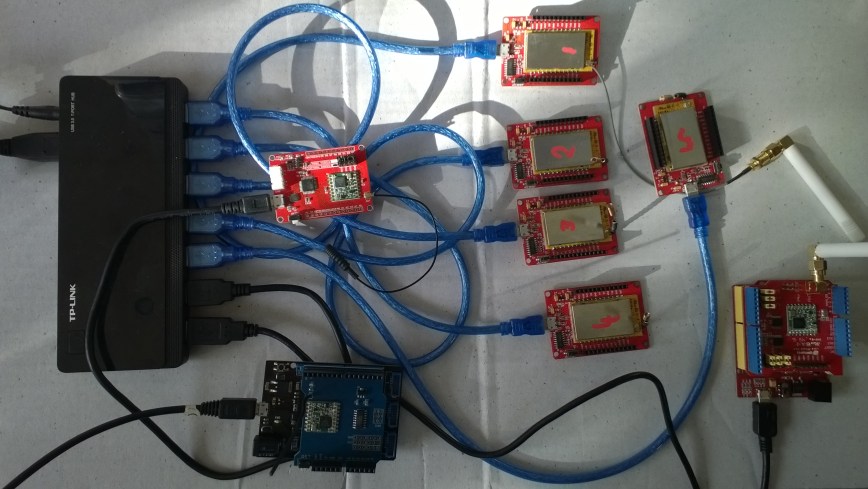
public sealed class StartupTask : IBackgroundTask
	{
		private const int ChipSelectLine = 25;
		private const int ResetLine = 17;
		private Rfm9XDevice rfm9XDevice = new Rfm9XDevice(ChipSelectLine, ResetLine);

		public void Run(IBackgroundTaskInstance taskInstance)
		{
			// Put device into LoRa + Sleep mode
			rfm9XDevice.RegisterWriteByte(0x01, 0b10000000); // RegOpMode

			// Set the frequency to 915MHz
			byte[] frequencyWriteBytes = { 0xE4, 0xC0, 0x00 }; // RegFrMsb, RegFrMid, RegFrLsb
			rfm9XDevice.RegisterWrite(0x06, frequencyWriteBytes);

			rfm9XDevice.RegisterWriteByte(0x0F, 0x0); // RegFifoRxBaseAddress

			rfm9XDevice.RegisterWriteByte(0x01, 0b10000101); // RegOpMode set LoRa & RxContinuous

			while (true)
			{
				// Wait until a packet is received, no timeouts in PoC
				Debug.WriteLine("Receive-Wait");
				byte IrqFlags = rfm9XDevice.RegisterReadByte(0x12); // RegIrqFlags
				while ((IrqFlags & 0b01000000) == 0)  // wait until RxDone cleared
				{
					Task.Delay(20).Wait();
					IrqFlags = rfm9XDevice.RegisterReadByte(0x12); // RegIrqFlags
					Debug.Write(".");
				}
				Debug.WriteLine("");

				if ((IrqFlags & 0b00100000) == 0b00100000)
				{
					Debug.WriteLine("Payload CRC error");
				}

				byte regHopChannel = rfm9XDevice.RegisterReadByte(0x1C);
				Debug.WriteLine(string.Format("regHopChannel {0}", Convert.ToString((byte)regHopChannel, 2).PadLeft(8, '0')));

				byte currentFifoAddress = rfm9XDevice.RegisterReadByte(0x10); // RegFifiRxCurrent
				rfm9XDevice.RegisterWriteByte(0x0d, currentFifoAddress); // RegFifoAddrPtr*
				byte numberOfBytes = rfm9XDevice.RegisterReadByte(0x13); // RegRxNbBytes

				// Allocate buffer for message
				byte[] messageBytes = new byte[numberOfBytes];

				for (int i = 0; i < numberOfBytes; i++)
				{
					messageBytes[i] = rfm9XDevice.RegisterReadByte(0x00); // RegFifo
				}
				rfm9XDevice.RegisterWriteByte(0x12, 0xff); // RegIrqFlags clear all the bits

				string messageText = UTF8Encoding.UTF8.GetString(messageBytes);
				Debug.WriteLine("Received {0} byte message {1}", messageBytes.Length, messageText);
				Debug.WriteLine(string.Format("RegIrqFlags {0}", Convert.ToString((byte)IrqFlags, 2).PadLeft(8, '0')));
				Debug.WriteLine("Receive-Done");
			}
		}
	}
The RegHopChannel register has a flag indicating whether there was a CRC extracted from the packet header.
regHopChannel 00000000
Received 23 byte message 1 Hello Arduino LoRa! 1
RegIrqFlags 01010000
Receive-Done
Receive-Wait
…………………………..
regHopChannel 00000000
Received 23 byte message 1 Hello Arduino LoRa! 2
RegIrqFlags 01010000
Receive-Done
Receive-Wait
……………………………
regHopChannel 00000000
Received 23 byte message 1 Hello Arduino LoRa! 3
RegIrqFlags 01010000
Receive-Done
Receive-Wait
I then modified my Arduino-LoRa library based client to include a CRC
void setup() {
  Serial.begin(9600);                   // initialize serial
  while (!Serial);

  Serial.println("LoRa Duplex - Set sync word");

  // override the default CS, reset, and IRQ pins (optional)
  LoRa.setPins(csPin, resetPin, irqPin);// set CS, reset, IRQ pin

  if (!LoRa.begin(915E6)) {             // initialize ratio at 915 MHz
    Serial.println("LoRa init failed. Check your connections.");
    while (true);                       // if failed, do nothing
  }

  LoRa.enableCrc();  // BHL This was my change

  LoRa.setSyncWord(0x12);           // ranges from 0-0xFF, default 0x34, see API docs

  LoRa.dumpRegisters(Serial);
  Serial.println("LoRa init succeeded.");
}

void loop() {
  if (millis() - lastSendTime > interval) {
    String message = "5 Hello Arduino LoRa! ";   // send a message
    message += msgCount;
    sendMessage(message);
    Serial.println("Sending " + message);
    lastSendTime = millis();            // timestamp the message
    //interval = random(2000) + 1000;    // 2-3 seconds
    interval = 1000;
  }

  // parse for a packet, and call onReceive with the result:
  onReceive(LoRa.parsePacket());
}

void sendMessage(String outgoing) {
  LoRa.beginPacket();                   // start packet
  LoRa.print(outgoing);                 // add payload
  LoRa.endPacket();                     // finish packet and send it
  msgCount++;                           // increment message ID
}

void onReceive(int packetSize) {
  if (packetSize == 0) return;          // if there's no packet, return

  // read packet header bytes:
  String incoming = "";

  while (LoRa.available()) {
    incoming += (char)LoRa.read();
  }

  Serial.println("Message: " + incoming);
  Serial.println("RSSI: " + String(LoRa.packetRssi()));
  Serial.println("Snr: " + String(LoRa.packetSnr()));
  Serial.println();
}
When I powered up a single client and the payload had a CRC
...............................
regHopChannel 01000000
Received 23 byte message 6 Hello Arduino LoRa! 6
RegIrqFlags 01010000
Receive-Done
Receive-Wait
.................................
regHopChannel 01000000
Received 23 byte message 6 Hello Arduino LoRa! 7
RegIrqFlags 01010000
Receive-Done
Receive-Wait
.................................
regHopChannel 01000000
Received 23 byte message 6 Hello Arduino LoRa! 8
RegIrqFlags 01010000
Receive-Done
Receive-Wait
...............................
Then when I increased the number of clients I started getting corrupted messages with CRC errors.
Received 24 byte message 6 Hello Arduino LoRa! 32
RegIrqFlags 01010000
Receive-Done
Receive-Wait
...............
regHopChannel 01000001
Received 25 byte message 8 Hello Arduino LoRa! 114
RegIrqFlags 01010000
Receive-Done
Receive-Wait
Payload CRC error
regHopChannel 01000000
Received 24 byte message s��=��(��p�^j�\ʏ�����
RegIrqFlags 01100000
Receive-Done
Receive-Wait
.............
regHopChannel 01000000
Received 24 byte message 6 Hello Arduino LoRa! 33
RegIrqFlags 01010000
Receive-Done
Receive-Wait
...............
regHopChannel 01000001
Received 25 byte message 8 Hello Arduino LoRa! 115
RegIrqFlags 01010000
Receive-Done
Receive-Wait
I need to do some more testing but now I think the problem was the RegIrqFlags PayloadCRCError flag was never going to get set because there was no CRC on the payload.

