Random wanderings through Microsoft Azure esp. PaaS plumbing, the IoT bits, AI on Micro controllers, AI on Edge Devices, .NET nanoFramework, .NET Core on *nix and ML.NET+ONNX
public interface IFormatterUplink
{
    public Message Evaluate(int organisationId, int deviceId, int deviceType, int userApplicationId, JObject telemetryEvent, JObject payloadJson, string payloadText, byte[] payloadBytes);
}
public class FormatterUplink : PayloadFormatter.IFormatterUplink
{
    public Message Evaluate(int organisationId, int deviceId, int deviceType, int userApplicationId, JObject telemetryEvent, JObject payloadJson, string payloadText, byte[] payloadBytes)
    {
        Message ioTHubmessage = new Message(Encoding.ASCII.GetBytes(JsonConvert.SerializeObject(telemetryEvent)));

        return ioTHubmessage;
    }
}
Satellite Passes with gap in coverage from 16:18 to 18:42 highlighted
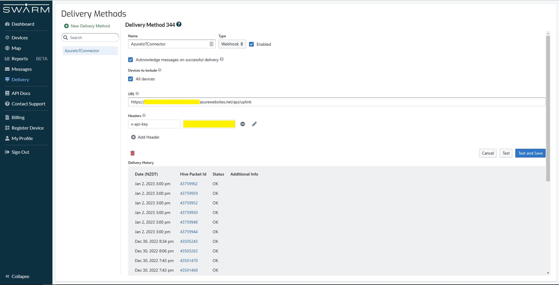
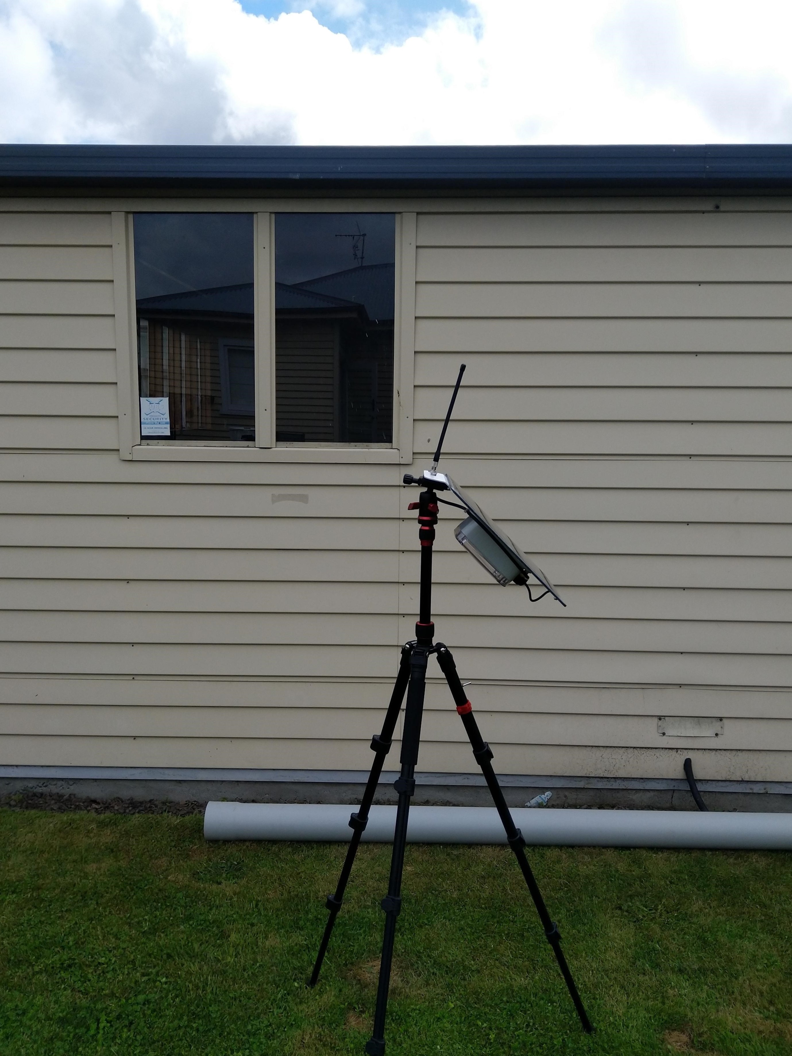
In the Swarm Hive Delivery Method messages from the Swarm Eval Kit and Swarm Tracker in my backyard arriving in “clusters”.
Swarm Hive Delivery Methods webhook calls.
The messages in each “cluster” were processed by a payload formatter then forwarded to Azure IoT Central for processing. All the messages in a cluster had similar event creation times which was “breaking” graphs and device tracking maps. After running the application locally using Telerik Fiddler to try different payloads I realised that the Microsoft.Azure.Azure.Devices.Client message iothub-creation-time-utc property was set to the when the message was received by Swarm Space infrastructure.
_logger.LogDebug("Uplink-DeviceId:{0} PacketId:{1} TelemetryEvent before:{0}", payload.DeviceId, payload.PacketId, JsonConvert.SerializeObject(telemetryEvent, Formatting.Indented));

telemetryEvent = swarmSpaceFormatterUplink.Evaluate(telemetryEvent, payload.Data, payloadBytes, payloadText, payloadJson);

_logger.LogDebug("Uplink-DeviceId:{0} PacketId:{1} TelemetryEvent after:{0}", payload.DeviceId, payload.PacketId, JsonConvert.SerializeObject(telemetryEvent, Formatting.Indented));

// Send the message to Azure IoT Hub
using (Message ioTHubmessage = new Message(Encoding.ASCII.GetBytes(JsonConvert.SerializeObject(telemetryEvent))))
{
   // Ensure the displayed time is the acquired time rather than the uploaded time.
   ioTHubmessage.Properties.Add("iothub-creation-time-utc", payload.HiveRxTime.ToString("s", CultureInfo.InvariantCulture));
   ioTHubmessage.Properties.Add("PacketId", payload.PacketId.ToString());
   ioTHubmessage.Properties.Add("OrganizationId", payload.OrganizationId.ToString());
   ioTHubmessage.Properties.Add("ApplicationId", payload.UserApplicationId.ToString());
   ioTHubmessage.Properties.Add("DeviceId", payload.DeviceId.ToString());
   ioTHubmessage.Properties.Add("deviceType", payload.DeviceType.ToString());

   await deviceClient.SendEventAsync(ioTHubmessage);

   _logger.LogInformation("Uplink-DeviceID:{deviceId} SendEventAsync success", payload.DeviceId);
}
The Swarm Eval Kit uplink (JSON) message generated by the sample firmware “d” field is the number of seconds since the Unix Epoch that the message payload was constructed.
Swarm Hive Messages with “d” field in the JSON payload highlighted
Online Unix Epoch Convertor displaying Unix Epoch 1672561286 in NZDT and UTC time
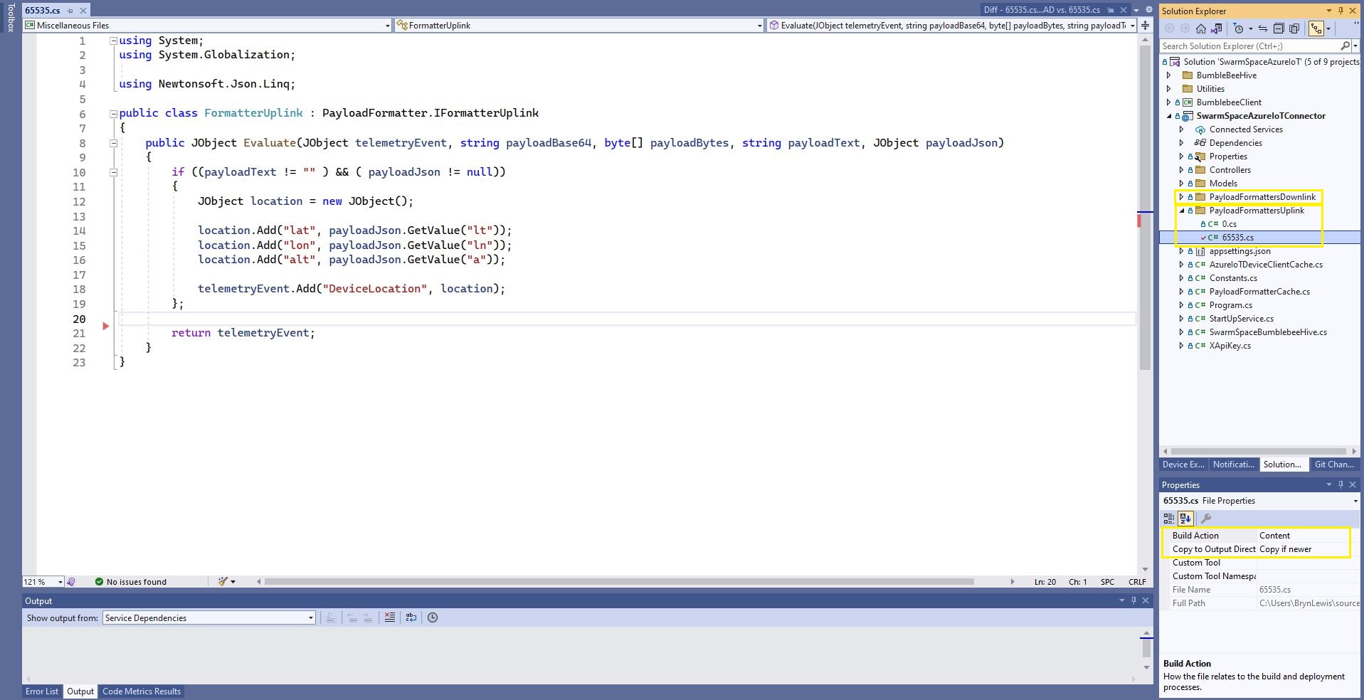
The revised 65355.cs payload formatter adds an “iothub-creation-time-utc” field to the TelemetryEvent
using System;
using System.Globalization;

using Newtonsoft.Json.Linq;

public class FormatterUplink : PayloadFormatter.IFormatterUplink
{
    public JObject Evaluate(JObject telemetryEvent, string payloadBase64, byte[] payloadBytes, string payloadText, JObject payloadJson)
    {
        if ((payloadText != "" ) && ( payloadJson != null))
        {
            JObject location = new JObject();

            location.Add("lat", payloadJson.GetValue("lt"));
            location.Add("lon", payloadJson.GetValue("ln"));
            location.Add("alt", payloadJson.GetValue("a"));

            telemetryEvent.Add("DeviceLocation", location);
        };

        telemetryEvent.Add("iothub-creation-time-utc", DateTimeOffset.FromUnixTimeSeconds((long)payloadJson.GetValue("d")).ToString("s", CultureInfo.InvariantCulture));

        return telemetryEvent;
    }
}
The payload formatters of my Azure IoT Hub Cloud Identity Translation Gateway use CS-Script and even a simple one was taking more than half a second to compile each time it was called.
using System;
using System.Globalization;

using Newtonsoft.Json.Linq;

public class FormatterUplink : PayloadFormatter.IFormatterUplink
{
    public JObject Evaluate(JObject telemetryEvent, string payloadBase64, byte[] payloadBytes, string payloadText, JObject payloadJson)
    {
        if ((payloadText != "" ) && ( payloadJson != null))
        {
            JObject location = new JObject();

            location.Add("lat", payloadJson.GetValue("lt"));
            location.Add("lon", payloadJson.GetValue("ln"));
            location.Add("alt", payloadJson.GetValue("a"));

            telemetryEvent.Add("Location", location);
        };

        return telemetryEvent;
    }
}
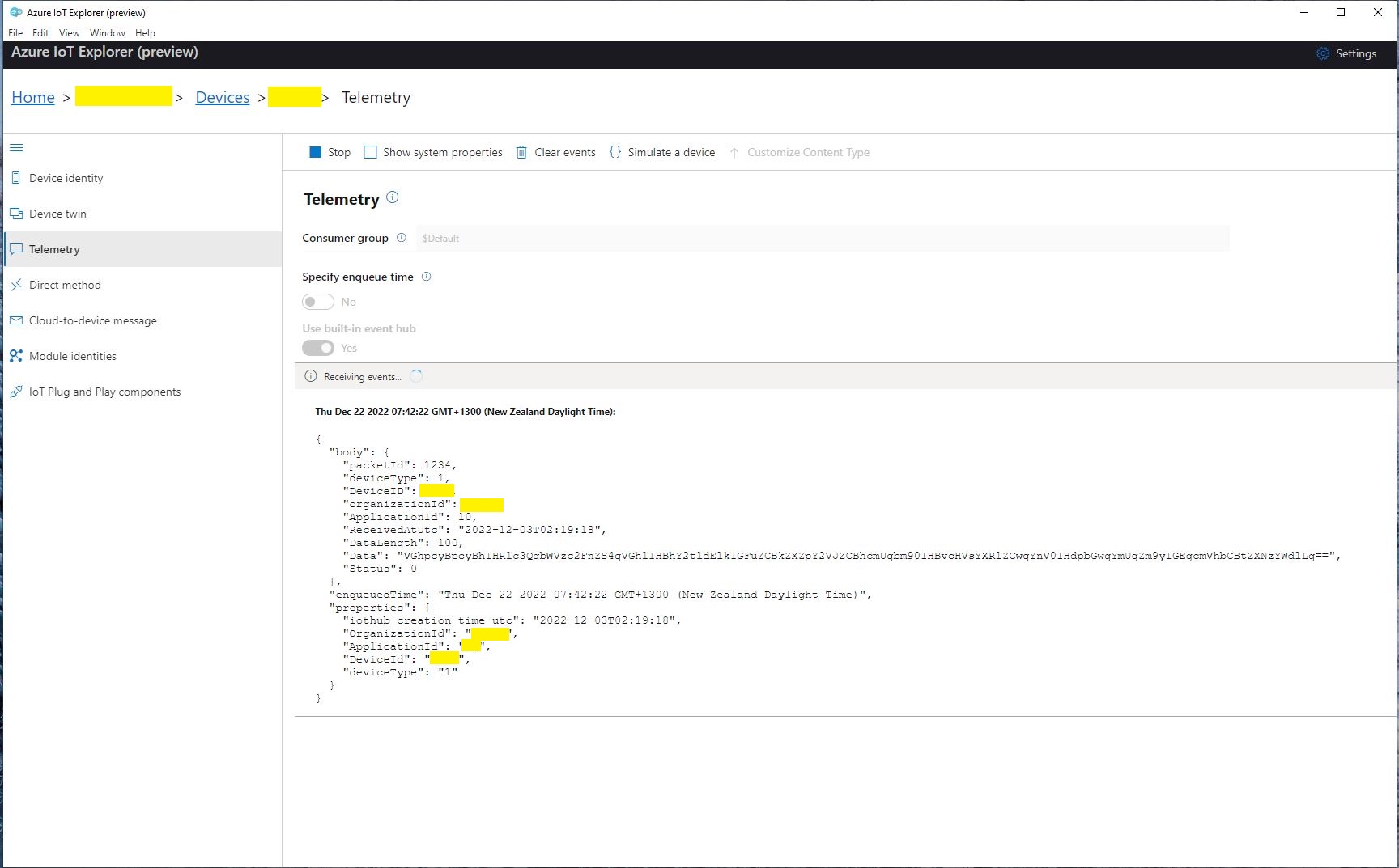
Azure IoT Central uplink telemetry message payload
The formatter files are currently part of the SwarmSpaceAzureIoTConnector project (moving to Azure Blob Storage) so are configured as “content” (bonus syntax highlighting works) and “copy if newer” so they are included in the deployment package.
public class FormatterCache : IFormatterCache
{
    private readonly ILogger<FormatterCache> _logger;
    private readonly Models.ApplicationSettings _applicationSettings;
    private readonly static IAppCache _payloadFormatters = new CachingService();

    public FormatterCache(ILogger<FormatterCache>logger, IOptions<Models.ApplicationSettings> applicationSettings)
    {
        _logger = logger;
        _applicationSettings = applicationSettings.Value;
    }

    public async Task<IFormatterUplink> UplinkGetAsync(int userApplicationId)
    {
        IFormatterUplink payloadFormatterUplink = await _payloadFormatters.GetOrAddAsync<PayloadFormatter.IFormatterUplink>($"U{userApplicationId}", (ICacheEntry x) => UplinkLoadAsync(userApplicationId), memoryCacheEntryOptions);

        return payloadFormatterUplink;
    }

    private async Task<IFormatterUplink> UplinkLoadAsync(int userApplicationId)
    {
        string payloadformatterFilePath = $"{_applicationSettings.PayloadFormattersUplinkFilePath}\\{userApplicationId}.cs";

        if (!File.Exists(payloadformatterFilePath))
        {
            _logger.LogInformation("PayloadFormatterUplink- UserApplicationId:{0} PayloadFormatterPath:{1} not found using default:{2}", userApplicationId, payloadformatterFilePath, _applicationSettings.PayloadFormatterUplinkDefault);

            return CSScript.Evaluator.LoadFile<PayloadFormatter.IFormatterUplink>(_applicationSettings.PayloadFormatterUplinkDefault);
        }

        _logger.LogInformation("PayloadFormatterUplink- UserApplicationId:{0} loading PayloadFormatterPath:{1}", userApplicationId, payloadformatterFilePath);

        return CSScript.Evaluator.LoadFile<PayloadFormatter.IFormatterUplink>(payloadformatterFilePath);
    }
...
}
The default uplink and downlink formatters are configured in application settings and are used when a UserApplicationId specific formatter is not configured.
Fiddler Composer illustrating compiled formatter timings before and after caching
const string codeSwarmSpaceUplinkFormatterCode = @"
   using Newtonsoft.Json.Linq;

   public class UplinkFormatter : PayloadFormatter.ISwarmSpaceFormatterUplink
   {
       public JObject Evaluate(JObject telemetryEvent, string payloadBase64, byte[] payloadBytes, string payloadText, JObject payloadJson)
       {
           if ((payloadText != """" ) && ( payloadJson != null))
           {
               JObject location = new JObject() ;

               location.Add(""Lat"", payloadJson.GetValue(""lt""));
               location.Add(""Lon"", payloadJson.GetValue(""ln""));
               location.Add(""Alt"", payloadJson.GetValue(""a""));

               telemetryEvent.Add( ""location"", location);
           };

           return telemetryEvent;
       }
   }";
}
The PayloadFormatter namespace was added to reduce the length of the payload formatter C# interface declarations.
namespace PayloadFormatter
{
    using Newtonsoft.Json.Linq;

    public interface ISwarmSpaceFormatterUplink
    {
        public JObject Evaluate(JObject telemetry, string payloadBase64, byte[] payloadBytes, string payloadText, JObject payloadJson);
    }

    public interface ISwarmSpaceFormatterDownlink
    {
        public string Evaluate(JObject payloadJson, string payloadText, byte[] payloadBytes, string payloadBase64);
    }
}

namespace devMobile.IoT.SwarmSpace.AzureIoT.Connector
{
    using System.Threading.Tasks;
    using Microsoft.Extensions.Logging;

    using CSScriptLib;

    using PayloadFormatter;

    public interface ISwarmSpaceFormatterCache
    {
        public Task<ISwarmSpaceFormatterUplink> PayloadFormatterGetOrAddAsync(int userApplicationId);

    }

    public class SwarmSpaceFormatterCache : ISwarmSpaceFormatterCache
    {
        private readonly ILogger<SwarmSpaceFormatterCache> _logger;

        public SwarmSpaceFormatterCache(ILogger<SwarmSpaceFormatterCache>logger)
        {
            _logger = logger;
        }

        public async Task<ISwarmSpaceFormatterUplink> PayloadFormatterGetOrAddAsync(int deviceId)
        {
            return CSScript.Evaluator.LoadCode<PayloadFormatter.ISwarmSpaceFormatterUplink>(codeSwarmSpaceUplinkFormatterCode);
        }
...
}
The parameters of the formatter are Base64 encoded, textual and a Newtonsoft JObject representations of the uplink payload and a telemetry event populated with some uplink message metadata.
Azure IoT Central uplink telemetry message payload
The initial “compile” of an uplink formatter was taking approximately 2.1 seconds so they will be “compiled” on demand and cached in a Dictionary with the UserApplicationId as the key. A default uplink formatter will be used when a UserApplicationId specific uplink formatter is not configured.
 https://json2csharp.com/

    // Root myDeserializedClass = JsonConvert.DeserializeObject<Root>(myJsonResponse);
    public class Root
    {
        public int packetId { get; set; }
        public int deviceType { get; set; }
        public int deviceId { get; set; }
        public int userApplicationId { get; set; }
        public int organizationId { get; set; }
        public string data { get; set; }
        public int len { get; set; }
        public int status { get; set; }
        public DateTime hiveRxTime { get; set; }
    }
*/
 public class UplinkPayload
    {
        [JsonProperty("packetId")]
        public int PacketId { get; set; }

        [JsonProperty("deviceType")]
        public int DeviceType { get; set; }

        [JsonProperty("deviceId")]
        public int DeviceId { get; set; }

        [JsonProperty("userApplicationId")]
        public int UserApplicationId { get; set; }

        [JsonProperty("organizationId")]
        public int OrganizationId { get; set; }

        [JsonProperty("data")]
        [JsonRequired]
        public string Data { get; set; }

        [JsonProperty("len")]
        public int Len { get; set; }

        [JsonProperty("status")]
        public int Status { get; set; }

        [JsonProperty("hiveRxTime")]
        public DateTime HiveRxTime { get; set; }
    }
This class is used to “automagically” deserialise Delivery Webhook payloads. There is also some additional payload validation which discards test messages (not certain this is a good idea) etc.
//---------------------------------------------------------------------------------
// Copyright (c) December 2022, devMobile Software
//
// Licensed under the Apache License, Version 2.0 (the "License");
// you may not use this file except in compliance with the License.
// You may obtain a copy of the License at
//
//     http://www.apache.org/licenses/LICENSE-2.0
//
// Unless required by applicable law or agreed to in writing, software
// distributed under the License is distributed on an "AS IS" BASIS,
// WITHOUT WARRANTIES OR CONDITIONS OF ANY KIND, either express or implied.
// See the License for the specific language governing permissions and
// limitations under the License.
//
//---------------------------------------------------------------------------------
namespace devMobile.IoT.SwarmSpace.AzureIoT.Connector.Controllers
{
    using System.Globalization;
    using System.Text;
    using System.Threading.Tasks;

    using Microsoft.AspNetCore.Mvc;
    using Microsoft.Azure.Devices.Client;
    using Microsoft.Extensions.Logging;

    using Newtonsoft.Json;
    using Newtonsoft.Json.Linq;

    [ApiController]
    [Route("api/[controller]")]
    public class UplinkController : ControllerBase
    {
        private readonly ILogger<UplinkController> _logger;
        private readonly IAzureIoTDeviceClientCache _azureIoTDeviceClientCache;

        public UplinkController(ILogger<UplinkController> logger, IAzureIoTDeviceClientCache azureIoTDeviceClientCache)
        {
            _logger = logger;
            _azureIoTDeviceClientCache = azureIoTDeviceClientCache;
        }

        [HttpPost]
        public async Task<IActionResult> Uplink([FromBody] Models.UplinkPayload payload)
        {
            DeviceClient deviceClient;

            _logger.LogDebug("Payload {0}", JsonConvert.SerializeObject(payload, Formatting.Indented));

            if (payload.PacketId == 0)
            {
                _logger.LogWarning("Uplink-payload simulated DeviceId:{DeviceId}", payload.DeviceId);

                return this.Ok();
            }

            if ((payload.UserApplicationId < Constants.UserApplicationIdMinimum) || (payload.UserApplicationId > Constants.UserApplicationIdMaximum))
            {
                _logger.LogWarning("Uplink-payload invalid User Application Id:{UserApplicationId}", payload.UserApplicationId);

                return this.BadRequest($"Invalid User Application Id {payload.UserApplicationId}");
            }

            if ((payload.Len < Constants.PayloadLengthMinimum) || string.IsNullOrEmpty(payload.Data))
            {
                _logger.LogWarning("Uplink-payload.Data is empty PacketId:{PacketId}", payload.PacketId);

                return this.Ok("payload.Data is empty");
            }

            Models.AzureIoTDeviceClientContext context = new Models.AzureIoTDeviceClientContext()
            {
                OrganisationId = payload.OrganizationId,
                UserApplicationId = payload.UserApplicationId,
                DeviceType = payload.DeviceType,
                DeviceId = payload.DeviceId,
            };

            deviceClient = await _azureIoTDeviceClientCache.GetOrAddAsync(payload.DeviceId.ToString(), context);

            JObject telemetryEvent = new JObject
            {
                { "packetId", payload.PacketId},
                { "deviceType" , payload.DeviceType},
                { "DeviceID", payload.DeviceId },
                { "organizationId", payload.OrganizationId },
                { "ApplicationId", payload.UserApplicationId},
                { "ReceivedAtUtc", payload.HiveRxTime.ToString("s", CultureInfo.InvariantCulture) },
                { "DataLength", payload.Len },
                { "Data", payload.Data },
                { "Status", payload.Status },
            };

            // Send the message to Azure IoT Hub
            using (Message ioTHubmessage = new Message(Encoding.ASCII.GetBytes(JsonConvert.SerializeObject(telemetryEvent))))
            {
                // Ensure the displayed time is the acquired time rather than the uploaded time.
                ioTHubmessage.Properties.Add("iothub-creation-time-utc", payload.HiveRxTime.ToString("s", CultureInfo.InvariantCulture));
                ioTHubmessage.Properties.Add("OrganizationId", payload.OrganizationId.ToString());
                ioTHubmessage.Properties.Add("ApplicationId", payload.UserApplicationId.ToString());
                ioTHubmessage.Properties.Add("DeviceId", payload.DeviceId.ToString());
                ioTHubmessage.Properties.Add("deviceType", payload.DeviceType.ToString());

                await deviceClient.SendEventAsync(ioTHubmessage);

                _logger.LogInformation("Uplink-DeviceID:{deviceId} SendEventAsync success", payload.DeviceId);
            }

            return this.Ok();
        }
    }
}
The webhook was configured to “acknowledge messages on successful delivery”. I then checked my Delivery Method configuration with a couple of “Test” messages.
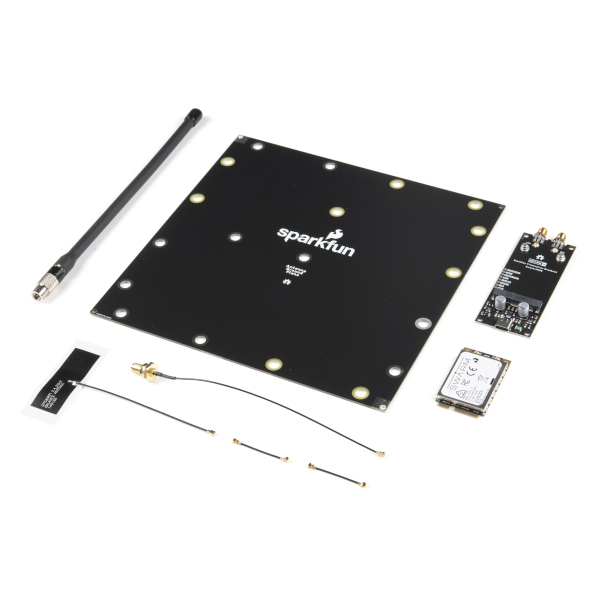
My Swarm Space Eval Kit arrived md-week and after some issues with jumper settings it started reporting position and status information.
I started with a modified version of the first sample on Github.
public class Samples
{
    const string codeMethod = @"
        int Multiply(int a, int b)
        {
            return a * b;
        }";

    public void Execute1()
    {
       dynamic script = CSScript.Evaluator.LoadMethod(codeMethod);

        int result = script.Multiply(3, 2);

        Console.WriteLine($"Product 1:{result}");
    }
...
internal class Program
{
    static void Main(string[] args)
    {
        new Samples().Execute1();
...
        Console.WriteLine($"Press Enter to exit");
        Console.ReadLine();
    }
}
I then modified it to use a C# interface and the application failed with an exception
CSScriptLib.CompilerException
  HResult=0x80131600
  Message=(2,39): error CS0246: The type or namespace name 'IMultiplier' could not be found (are you missing a using directive or an assembly reference?)

  Source=CSScriptLib
  StackTrace:
   at CSScriptLib.RoslynEvaluator.Compile(String scriptText, String scriptFile, CompileInfo info)
   at CSScriptLib.EvaluatorBase`1.LoadCode[T](String scriptText, Object[] args)
   at devMobile.IoT.SwarmSpace.AzureIoT.PayloadFormatterCSScript.Samples.Execute2A() in C:\Users\BrynLewis\source\repos\SwarmSpaceAzureIoT\PayloadFormatterCSScipt\Program.cs:line 90
   at devMobile.IoT.SwarmSpace.AzureIoT.PayloadFormatterCSScript.Program.Main(String[] args) in C:\Users\BrynLewis\source\repos\SwarmSpaceAzureIoT\PayloadFormatterCSScipt\Program.cs:line 375
After some trial and error, I figured out I had the namespace wrong
const string codeClassA = @"
    public class Calculator : devMobile.IoT.SwarmSpace.AzureIoT.PayloadFormatterCSScript.IMultiplier
    {
        public int Multiply(int a, int b)
        {

            return a * b;
        }
    }";

public void Execute2A()
{
    IMultiplier multiplierA = CSScript.Evaluator.LoadCode<IMultiplier>(codeClassA);

    Console.WriteLine($"Product 2A:{multiplierA.Multiply(3, 2)} - Press Enter to exit");
}
The long namespace would have been a pain in the arse (PITA) for users creating payload formatters and after some experimentation I added another interface with a short namespace. (Not certain this is a good idea).
namespace PayloadFormatter // Additional namespace for shortening interface for formatters
{
    public interface IMultiplier
    {
        int Multiply(int a, int b);
    }
}
...
public void Execute2B()
{
      PayloadFormatter.IMultiplier multiplierB = CSScript.Evaluator.LoadCode<PayloadFormatter.IMultiplier>(codeClassB);

     Console.WriteLine($"Product 2B:{multiplierB.Multiply(3, 2)} - Press Enter to exit");
}
I then wanted to figure out how to limit the namepaces the script has access to
const string codeClassDebug = @"
    using System.Diagnostics;

    public class Calculator : devMobile.IoT.SwarmSpace.AzureIoT.PayloadFormatterCSScript.IMultiplier
    {
        public int Multiply(int a, int b)
        {
           Debug.WriteLine(""Oops""); // Comment out the using System.Diagnostics;

            return a * b;
        }
    }";

public void Execute3()
{
    CSScript.Evaluator.Reset(true);

    IMultiplier multiplier = CSScript.Evaluator
        .LoadCode<IMultiplier>(codeClassDebug);

    int result = multiplier.Multiply(6, 2);

    Console.WriteLine($"Product 3:{result}");
}
The CSScript.Evaluator.Reset(true); removes all of the “default” references but a using directive could make namespaces available, so this needs some more investigation
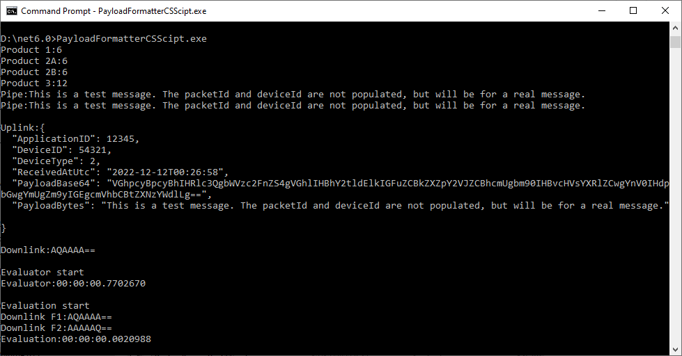
The next step was to build the simplest possible payload formatter a “pipe” which displayed the text encoded in Base64 string.
const string codeSwarmSpaceFormatterPipe = @"
    public class SwarmSpaceFormatter:devMobile.IoT.SwarmSpace.AzureIoT.PayloadFormatterCSScript.ISwarmSpaceFormatterPipe
    {
        public string Pipe(string payloadBase64)
        {
            var payloadBase64Bytes = System.Convert.FromBase64String(payloadBase64);

             return System.Text.Encoding.UTF8.GetString(payloadBase64Bytes);
        }
    }";
...
public void Execute4()
{
    ISwarmSpaceFormatterPipe SwarmSpaceFormatter = CSScript.Evaluator
           ...
                        .LoadCode<ISwarmSpaceFormatterPipe>(codeSwarmSpaceFormatterPipe);

    string payload = SwarmSpaceFormatter.Pipe(PayloadBase64);

    Console.WriteLine($"Pipe:{payload}");
}
The Base64 encoded uplink payloads will have to be converted to JSON and the downlink JSON payloads will have to be converted to Base64 encoded binary, so I created an uplink and downlink formatters.
I found that having both the byte array and Base64 encoded representation of the uplink payloads was useful. The first formatter converts the temperature field of the downlink payload into a four byte array then reverses the array to illustrate how packed byte payloads could be constructed.
const string codeSwarmSpaceFormatter1 = @"
    public class SwarmSpaceFormatter : devMobile.IoT.SwarmSpace.AzureIoT.PayloadFormatterCSScript.ISwarmSpaceFormatter
    {
        public string Pipe(string payloadBase64)
        {
            var payloadBase64Bytes = System.Convert.FromBase64String(payloadBase64);

            return System.Text.Encoding.UTF8.GetString(payloadBase64Bytes);
       }

        public JObject Uplink(JObject telemetryEvent, string payloadBase64, byte[] payloadBytes)
        {
            var payloadBase64Bytes = System.Convert.FromBase64String(payloadBase64);

            telemetryEvent.Add(""PayloadBase64"", payloadBase64Bytes);
            telemetryEvent.Add(""PayloadBytes"",System.Text.Encoding.UTF8.GetString(payloadBytes));

            return telemetryEvent;
        }

        public string Downlink(JObject command)
        {
            int temperature = command.Value<int>(""Temperature"");

            return System.Convert.ToBase64String(BitConverter.GetBytes(temperature));
        }
    }";

const string codeSwarmSpaceFormatter2 = @"
    public class SwarmSpaceFormatter:devMobile.IoT.SwarmSpace.AzureIoT.PayloadFormatterCSScript.ISwarmSpaceFormatter
    {
        public string Pipe(string payloadBase64)
        {
            var payloadBase64Bytes = System.Convert.FromBase64String(payloadBase64);

            return System.Text.Encoding.UTF8.GetString(payloadBase64Bytes);
        }

        public JObject Uplink(JObject telemetryEvent, string payloadBase64, byte[] payloadBytes)
        {
            var payloadBase64Bytes = System.Convert.FromBase64String(payloadBase64);

            telemetryEvent.Add(""PayloadBase64"", payloadBase64Bytes);
            telemetryEvent.Add(""PayloadBytes"",System.Text.Encoding.UTF8.GetString(payloadBytes));

            return telemetryEvent;
        }

        public string Downlink(JObject command)
        {
            int temperature = command.Value<int>(""Temperature"");

            byte[] temperatureBytes = BitConverter.GetBytes(temperature);

            Array.Reverse(temperatureBytes);

            return System.Convert.ToBase64String(temperatureBytes);
        }
    }";
...
public void Execute6()
{
    string namespaces = $"using Newtonsoft.Json.Linq;using System;\n";
    string code1 = namespaces + codeSwarmSpaceFormatter1;
    string code2 = namespaces + codeSwarmSpaceFormatter2;

    JObject telemetry = new JObject
    {
        { "ApplicationID", 12345 },
        { "DeviceID", 54321 },
        { "DeviceType", 2 },
        { "ReceivedAtUtc", DateTime.UtcNow.ToString("s", CultureInfo.InvariantCulture) },
    };

    var formatters = new Dictionary<string, ISwarmSpaceFormatter>();

    Console.WriteLine($"Evaluator start");
    DateTime evaluatorStartAtUtc = DateTime.UtcNow;

    ISwarmSpaceFormatter SwarmSpaceFormatter1 = CSScript.Evaluator
                                  .LoadCode<ISwarmSpaceFormatter>(code1);

    ISwarmSpaceFormatter SwarmSpaceFormatter2 = CSScript.Evaluator
                                  .LoadCode<ISwarmSpaceFormatter>(code2);

    Console.WriteLine($"Evaluator:{DateTime.UtcNow - evaluatorStartAtUtc}");
    Console.WriteLine("");

    Console.WriteLine($"Evaluation start");
    DateTime evaluationStartUtc = DateTime.UtcNow;

    formatters.Add("F1", SwarmSpaceFormatter1);
    formatters.Add("F2", SwarmSpaceFormatter2);

    JObject command = new JObject
    {
        {"Temperature", 1},
    };

    ISwarmSpaceFormatter downlinkPayload;
    downlinkPayload = formatters["F1"];
    Console.WriteLine($"Downlink F1:{downlinkPayload.Downlink(command)}");

    downlinkPayload = formatters["F2"];
    Console.WriteLine($"Downlink F2:{downlinkPayload.Downlink(command)}");

    Console.WriteLine($"Evaluation:{DateTime.UtcNow - evaluationStartUtc}");
    Console.WriteLine("");

    const int iterations = 100;
    Console.WriteLine($"Evaluations start {iterations}");
    DateTime evaluationsStartUtc = DateTime.UtcNow;

    for (int i = 1; i <= iterations; i++)
    {
        JObject command1 = new JObject
        {
            {"Temperature", 1},
        };

        downlinkPayload = formatters["F1"];
        Console.WriteLine($" Downlink F1:{downlinkPayload.Downlink(command1)}");

        downlinkPayload = formatters["F2"];
        Console.WriteLine($" Downlink F2:{downlinkPayload.Downlink(command1)}");
    }

    Console.WriteLine($"Evaluations:{iterations} Took:{DateTime.UtcNow - evaluationsStartUtc}");
}
On my development box the initial “compile” of each function was taking approximately 2.1 seconds so I cached the “compiled” formatters in a dictionary so they could be reused. Cached in the dictionary executing the two formatters 100 times took approximately 15 milliseconds (which is close to native .NET performance).
Compatibility
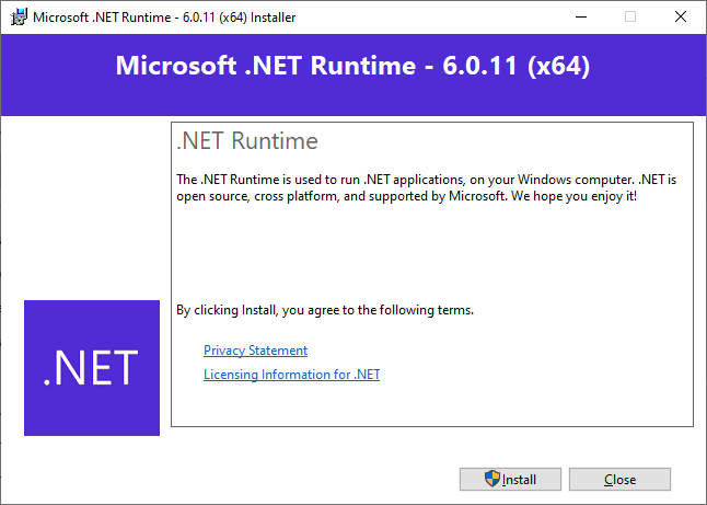
To check that the CS-Script tooling could run on a machine without the .NET 6 Software Development Kit (SDK) I tested the application on a laptop which had a “fresh” install of Windows 10.
CS-Script application failing due to missing .NET 6 runtime
Installing the .NET 6 Runtime
CS-Script application running after .NET runtime installation
The CS-Script library is pretty amazing and has made the development of uplink and downlink payload formatters significantly less complex than I was expecting.
To figure out how to poll the Swarm Hive API I have built yet another “nasty” Proof of Concept (PoC) which gets ToDevice and FromDevice messages. Initially I have focused on polling as the volume of messages from my single device is pretty low (WebHooks will be covered in a future post).
NOTE: Swarm Space technical support clarified the parameter values required to get FromDevice and ToDevice messages using the Bumbleebee Hive API.
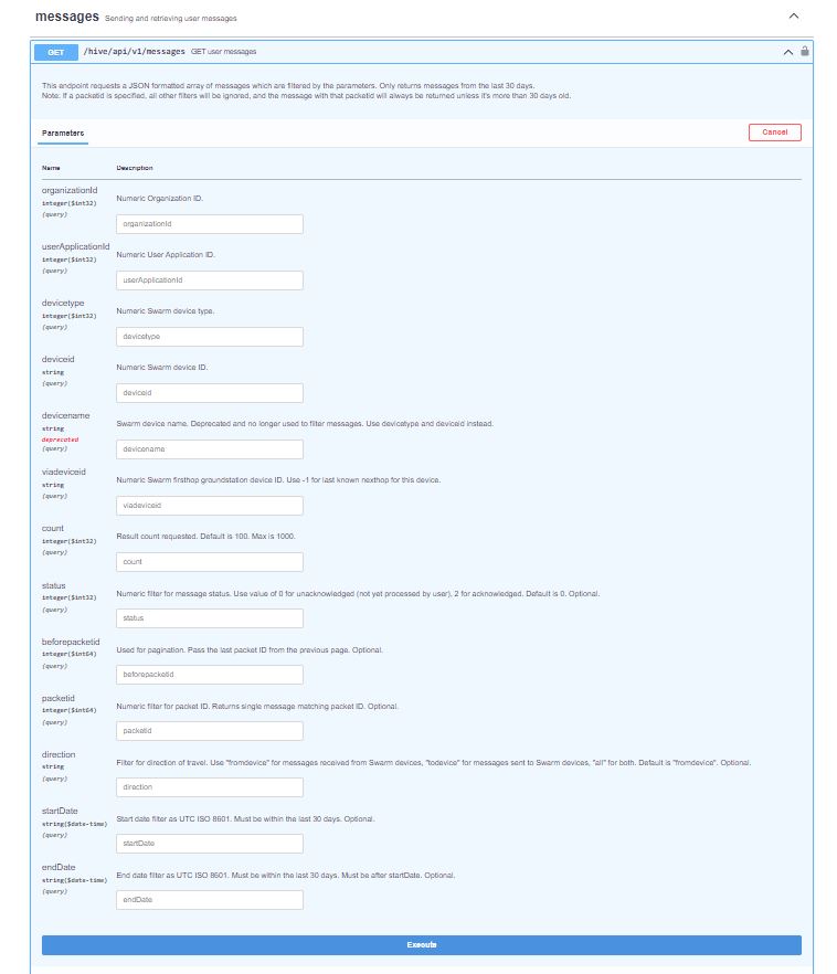
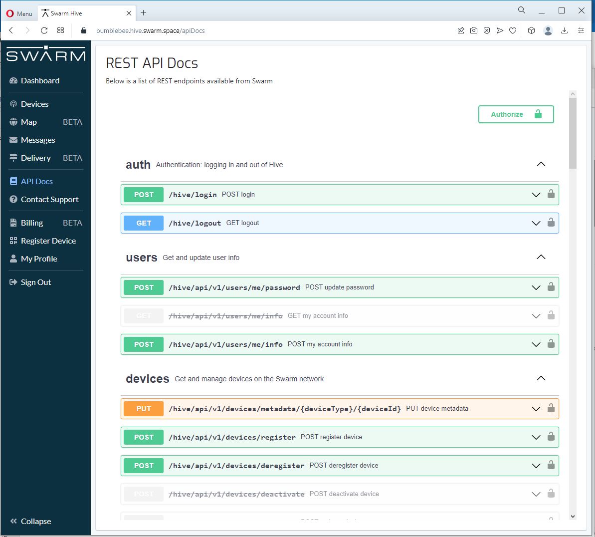
Swarm API Docs messages functionality
The Messages Get method has a lot of parameters for filtering and paging the response message lists. Many of the parameters have default values so can be null or left blank.
Swarm API Get User Message filters
I started off by seeing if I could duplicate the functionality of the user interface and get a list of all ToDevice and FromDevice messages.
Swarm Dashboard messages list
I first called the Messages Get method with the direction set to “fromdevice” (Odd this is a string rather than an enumeration) and the messages I had sent from my Sparkfun Satellite Transceiver Breakout – Swarm M138 were displayed.
Swarm API Docs displaying “fromdevice” messages
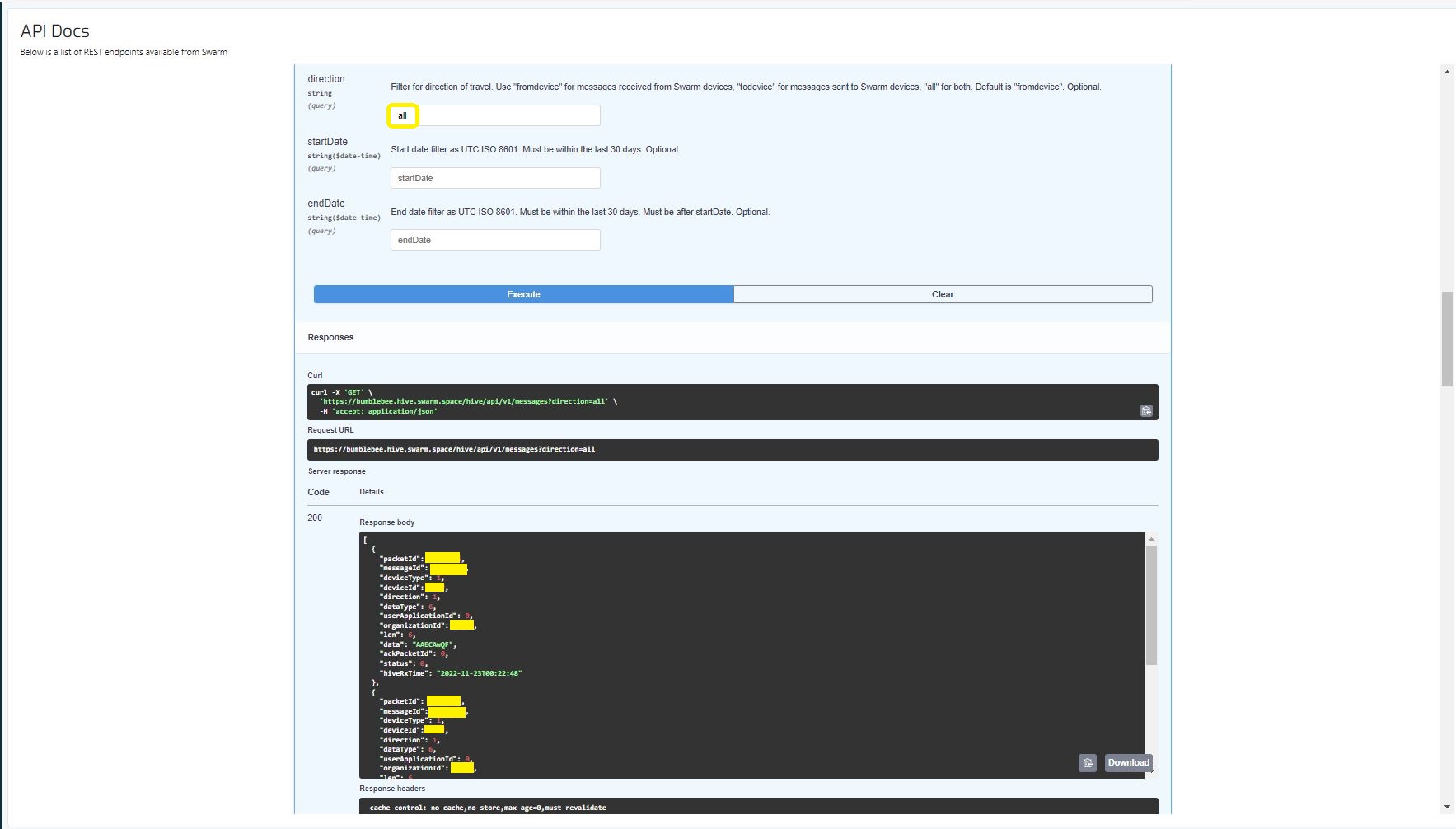
I then called the Messages Get method with the direction set to “all” and only the FromDevice messages were displayed which I wasn’t expecting.
Swarm API Docs displaying ToDevice and FromDevices messages
I then called the Messages Get method with the direction set to “FromDevice and no messages were displayed which I wasn’t expecting
Swarm API Docs displaying “todevice” messages
I then called the Message Get method with the messageId of a ToDevice message and the detailed message information was displayed.
Swarm API Docs displaying the details of a specific inbound message
For testing I configured 5 devices (a real device and the others simulated) in my Azure IoT Hub with the Swarm Device ID ued as the Azure IoT Hub device ID.
While testing I disabled the message RxAck functionality so I could repeatedly call the MessagesGet method so I didn’t have to send new messages and burn through my 50 free messages.
Azure IoT Explorer telemetry displaying the three messages processed by my console application.
.
Updated parameters based on feedback from Swarm technical support
So, I can simulate lots of devices and test more complex configurations I have started build a Swarm Bumble Bee Hive emulator based on the API and Delivery-APIOpenAPI files.
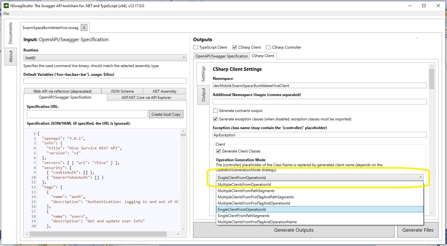
NSwagStudio configuration for generating ASP.NET Core web API
As well as generating clients NSwagStudio can also generate ASP.NET Core web APIs. To test my approach, I built the simplest possible client I could which calls the generated PostLoginAsync and GetDeviceCountAsync.
Swagger UI for NSwagStudio generated ASP.NET Core web API
BumblebeeHiveBasicClientConsole application 415 Unsupported Media Type error
After some trial and error, I modified the HiveController.cs and HiveControllerImplementation.cs Login method signatures so the payload was “application/x-www-form-urlencoded” rather than “application/json” by changing FromBody to FromForm
Modifying code generated by a tool like NSwagStudio should be avoided but I couldn’t work out a simpler solution
/// <summary>
/// POST login
/// </summary>
/// <remarks>
/// <p>Use username and password to log in.</p><p>On success: returns status code 200. The response body is the JSON <code>{"token": "&lt;token&gt;"}</code>, along with the header <code>Set-Cookie: JSESSIONID=&lt;token&gt;; Path=/; Secure; HttpOnly;</code>. The tokens in the return value and the <code>Set-Cookie</code> header are the same. The token is a long string of letters, numbers, and punctuation.</p><p>On failure: returns status code 401.</p><p>To make authenticated requests, there are two ways: <ul><li>(Preferred) Use the token as a Bearer Authentication token by including the HTTP header <code>Authorization: Bearer &lt;token&gt;</code> in further requests.</li><li>(Deprecated) Use the token as the JSESSIONID cookie in further requests.</li></ul></p>
/// </remarks>
/// <returns>Login success</returns>
[Microsoft.AspNetCore.Mvc.HttpPost, Microsoft.AspNetCore.Mvc.Route("login")]
public System.Threading.Tasks.Task<Response> PostLogin([Microsoft.AspNetCore.Mvc.FromForm] LoginForm body)
{
return _implementation.PostLoginAsync(body);
}
BumblebeeHiveBasicCLientConsole application calling the simulator
BumblebeeHiveBasicClientConsole application calling the production system
After some initial problems with content-types the Swarm Hive API (not tried the Delivery-API yet) appears to be documented and easy to use. Though, some of the variable type choices do seem a bit odd.
public virtual async System.Threading.Tasks.Task<string> GetDeviceCountAsync(int? devicetype, System.Threading.CancellationToken cancellationToken)
I have started with a “nasty” Proof of Concept(PoC) to figure out how to connect to the Swarm Hive API.
The Swarm Hive API has been published with Swagger/OpenAPI which is really simple to use. I used NSwagStudio to generate a C# client to I didn’t have to “handcraft” one.
Initially the code would compile but I found a clue in a Github Issue from September 2017 which was to change the “Operation Generation Model” to SingleClientFromOperationId.(The setting is highlighted above).
I tried a couple of ways to attach the Swarm Hive API authorisation token (returned by the Login method) to client requests. After a couple for failed attempts, I “realised” that adding the “Authorization” header to the HttpClientdefaultRequestHeaders was by far the simplest approach.
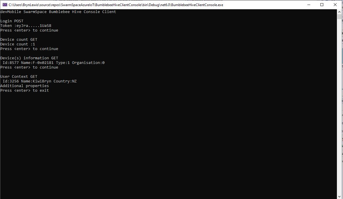
My “nasty” console application calls the Login method, then requests the number of devices (I only have one), gets a list of the properties of all the devices(very short list) then gets the User Context and displays their ID, Name and Country.