Random wanderings through Microsoft Azure esp. PaaS plumbing, the IoT bits, AI on Micro controllers, AI on Edge Devices, .NET nanoFramework, .NET Core on *nix and ML.NET+ONNX
I had been planning this for a while, then the code broke when I tried to build a version for my SparkFun LoRa Gateway-1-Channel (ESP32). There was a namespace (static configuration class in configuration.cs) collision and the length of SX127XDevice.cs file was getting silly.
This refactor took a couple of days and really changed the structure of the library.
VS2022 Solution structure after refactoring
I went through the SX127XDevice.cs extracting the enumerations, masks and defaults associated with the registers the library supports.
The library is designed to be a approximate .NET nanoFramework equivalent of Arduino-LoRa so it doesn’t support/implement all of the functionality of the SemtechSX127X. Still got a bit of refactoring to go but the structure is slowly improving.
I use Fork to manage my Github repositories, it’s an excellent product especially as it does a pretty good job of keeping me from screwing up.
While updating my.NET nanoFrameworkSemtech SX127X library I revisited (because I thought it might still be wrong) how the output power is calculated. I started with the overview of the transmitter architecture in in the datasheet…
SX127X Overview of transmission pipeline
The RegPaConfig register has three settings PaSelect(RFO & PA_BOOST), MaxPower(0..7), and OutputPower(0..15). When in RFO mode the pOut has a range of -4 to 15 and PA_BOOST mode has a range of 2 to 20. (The AdaFruitversion of the RadioHead library has differences to the Semtech Lora-net/LoRaMac-Node libraries)
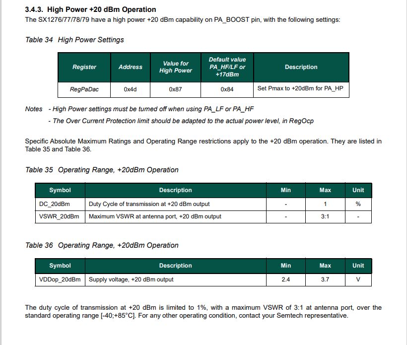
The SX127X also has a power amplifier attached to the PA_BOOST pin and a higher power amplifier which is controlled by the RegPaDac register.
High power mode overview
RegPaDac register configuration options
The RegOcp (over current protection) has to be relaxed for the higher power modes
RegPaConfig register configuration options
I started with the Semtech Lora-net/LoRaMac-Node library which reads the RegPaConfig, RegPaSelect and RegPaDac registers then does any updates required.
I also reviewed the Arduino-LoRaSemtech library which only writes to the RegPaConfig, RegPaSelect and RegPaDac registers.
void LoRaClass::setTxPower(int level, int outputPin)
{
  if (PA_OUTPUT_RFO_PIN == outputPin) {
    // RFO
    if (level < 0) {
      level = 0;
    } else if (level > 14) {
      level = 14;
    }

    writeRegister(REG_PA_CONFIG, 0x70 | level);
  } else {
    // PA BOOST
    if (level > 17) {
      if (level > 20) {
        level = 20;
      }

      // subtract 3 from level, so 18 - 20 maps to 15 - 17
      level -= 3;

      // High Power +20 dBm Operation (Semtech SX1276/77/78/79 5.4.3.)
      writeRegister(REG_PA_DAC, 0x87);
      setOCP(140);
    } else {
      if (level < 2) {
        level = 2;
      }
      //Default value PA_HF/LF or +17dBm
      writeRegister(REG_PA_DAC, 0x84);
      setOCP(100);
    }

    writeRegister(REG_PA_CONFIG, PA_BOOST | (level - 2));
  }
}
I updated the output power configuration code in the Initialise method of the SX127X library. After reviewing the SX127X datasheet I extended the way the pOut is calculated in RFO mode. The code uses two values for MaxPower(RegPAConfigMaxPower.Min & RegPAConfigMaxPower.Max) so that the full RTO output power range was available.
// Set RegPAConfig & RegPaDac if powerAmplifier/OutputPower settings not defaults
if ((powerAmplifier != Configuration.RegPAConfigPASelect.Default) || (outputPower != Configuration.OutputPowerDefault))
{
	if (powerAmplifier == Configuration.RegPAConfigPASelect.PABoost)
	{
		byte regPAConfigValue = (byte)Configuration.RegPAConfigPASelect.PABoost;

		// Validate the minimum and maximum PABoost outputpower
		if ((outputPower < Configuration.OutputPowerPABoostMin) || (outputPower > Configuration.OutputPowerPABoostMax))
		{
			throw new ApplicationException($"PABoost {outputPower}dBm Min power {Configuration.OutputPowerPABoostMin} to Max power {Configuration.OutputPowerPABoostMax}");
		}

		if (outputPower < Configuration.OutputPowerPABoostPaDacThreshhold)
		{
			// outputPower 0..15 so pOut is 2=17-(15-0)...17=17-(15-15)
			regPAConfigValue |= (byte)Configuration.RegPAConfigMaxPower.Default;
			regPAConfigValue |= (byte)(outputPower - 2);

			_registerManager.WriteByte((byte)Configuration.Registers.RegPAConfig, regPAConfigValue);
			_registerManager.WriteByte((byte)Configuration.Registers.RegPaDac, (byte)Configuration.RegPaDac.Normal);
		}
		else
		{
			// outputPower 0..15 so pOut is 5=20-(15-0)...20=20-(15-15) // See https://github.com/adafruit/RadioHead/blob/master/RH_RF95.cpp around line 411 could be 23dBm
			regPAConfigValue |= (byte)Configuration.RegPAConfigMaxPower.Default;
			regPAConfigValue |= (byte)(outputPower - 5);

			_registerManager.WriteByte((byte)Configuration.Registers.RegPAConfig, regPAConfigValue);
			_registerManager.WriteByte((byte)Configuration.Registers.RegPaDac, (byte)Configuration.RegPaDac.Boost);
		}
	}
	else
	{
		byte regPAConfigValue = (byte)Configuration.RegPAConfigPASelect.Rfo;

		// Validate the minimum and maximum RFO outputPower
		if ((outputPower < Configuration.OutputPowerRfoMin) || (outputPower > Configuration.OutputPowerRfoMax))
		{
			throw new ApplicationException($"RFO {outputPower}dBm Min power {Configuration.OutputPowerRfoMin} to Max power {Configuration.OutputPowerRfoMax}");
		}

		// Set MaxPower and Power calculate pOut = PMax-(15-outputPower), pMax=10.8 + 0.6*MaxPower
		if (outputPower > Configuration.OutputPowerRfoThreshhold)
		{
			// pMax 15=10.8+0.6*7 with outputPower 0...15 so pOut is 15=pMax-(15-0)...0=pMax-(15-15)
			regPAConfigValue |= (byte)Configuration.RegPAConfigMaxPower.Max;
			regPAConfigValue |= (byte)(outputPower + 0);
		}
		else
		{
			// pMax 10.8=10.8+0.6*0 with output power 0..15 so pOut is -4=10-(15-0)...10.8=10.8-(15-15)
			 regPAConfigValue |= (byte)Configuration.RegPAConfigMaxPower.Min;
			regPAConfigValue |= (byte)(outputPower + 4);
		}

		_registerManager.WriteByte((byte)Configuration.Registers.RegPAConfig, regPAConfigValue);
		_registerManager.WriteByte((byte)Configuration.Registers.RegPaDac, (byte)Configuration.RegPaDac.Normal);
	}
}
The formula for pOut and pMax in RegPaConfig documentation is included in the source code so I could manually calculate (including edge cases) the values as part of my testing. I ran the SX127XLoRaDeviceClient and inspected the PaConfig & RegPaDac in the Visual Studio 2022 debugger.
PABoost
Output power = 1
Output power = 21
Exception

Output power = 2
PaConfig = 192
RegPaDac = normal
	1100 0000

Output power = 16
PaConfig = 206
RegPaDac = normal
	1100 1110

Output power = 17
PaConfig = 204
RegPacDac = Normal
	1100 1100

Output power = 18
PaConfig = 205
RegPacDac = Boost
	1100 1101

Output power = 19
PaConfig = 206
RegPacDac = Boost
	1100 1110

Output power = 20
PaConfig = 207
RegPacDac = Boost
	1100 1111

RFO
Output power = -5
Output power = 16
Exception

Output power = -4
PAConfig = 0
	0000 0000

Output power = -1
PAConfig = 3
	0000 0011

Output power = 0
PAConfig = 4
	0000 0100

Output power = 1
PAConfig = 113
	0111 0001

OutputPower = 14
PAConfig = 126
	0111 1110

OutputPower = 15
PAConfig = 127
	0111 1111
I need to borrow some test gear to check my implementation