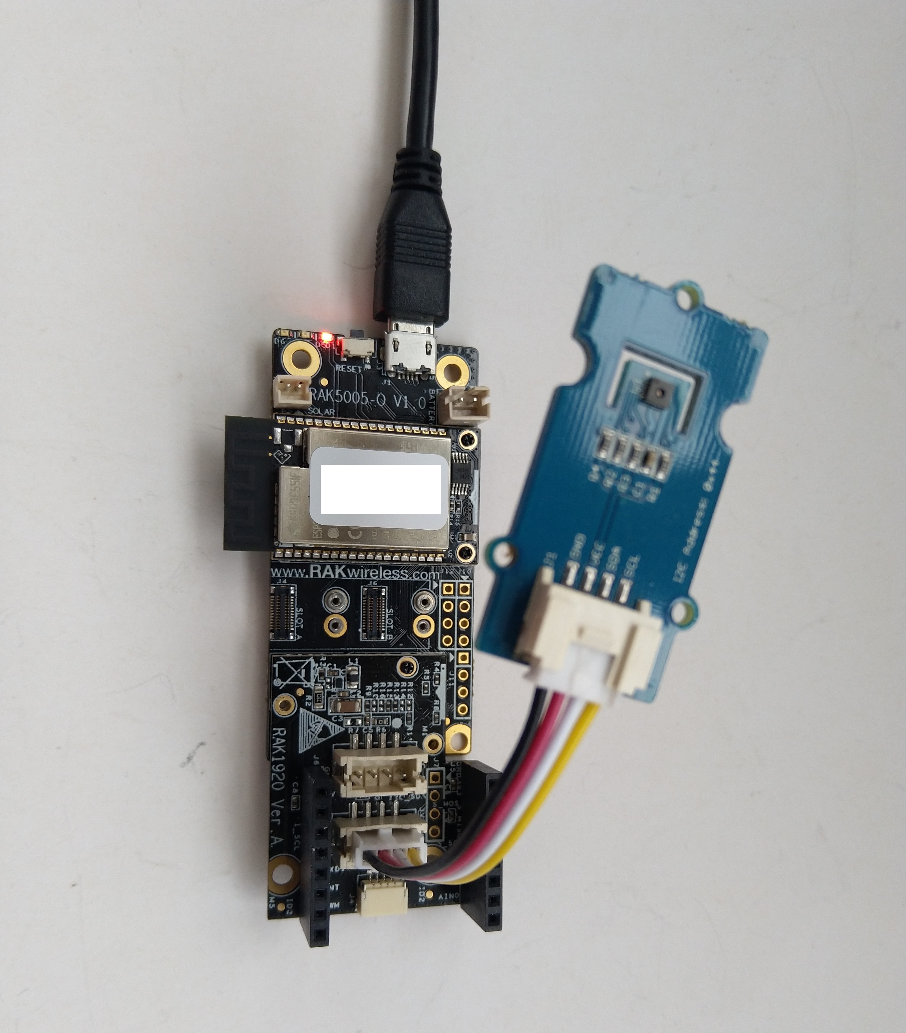
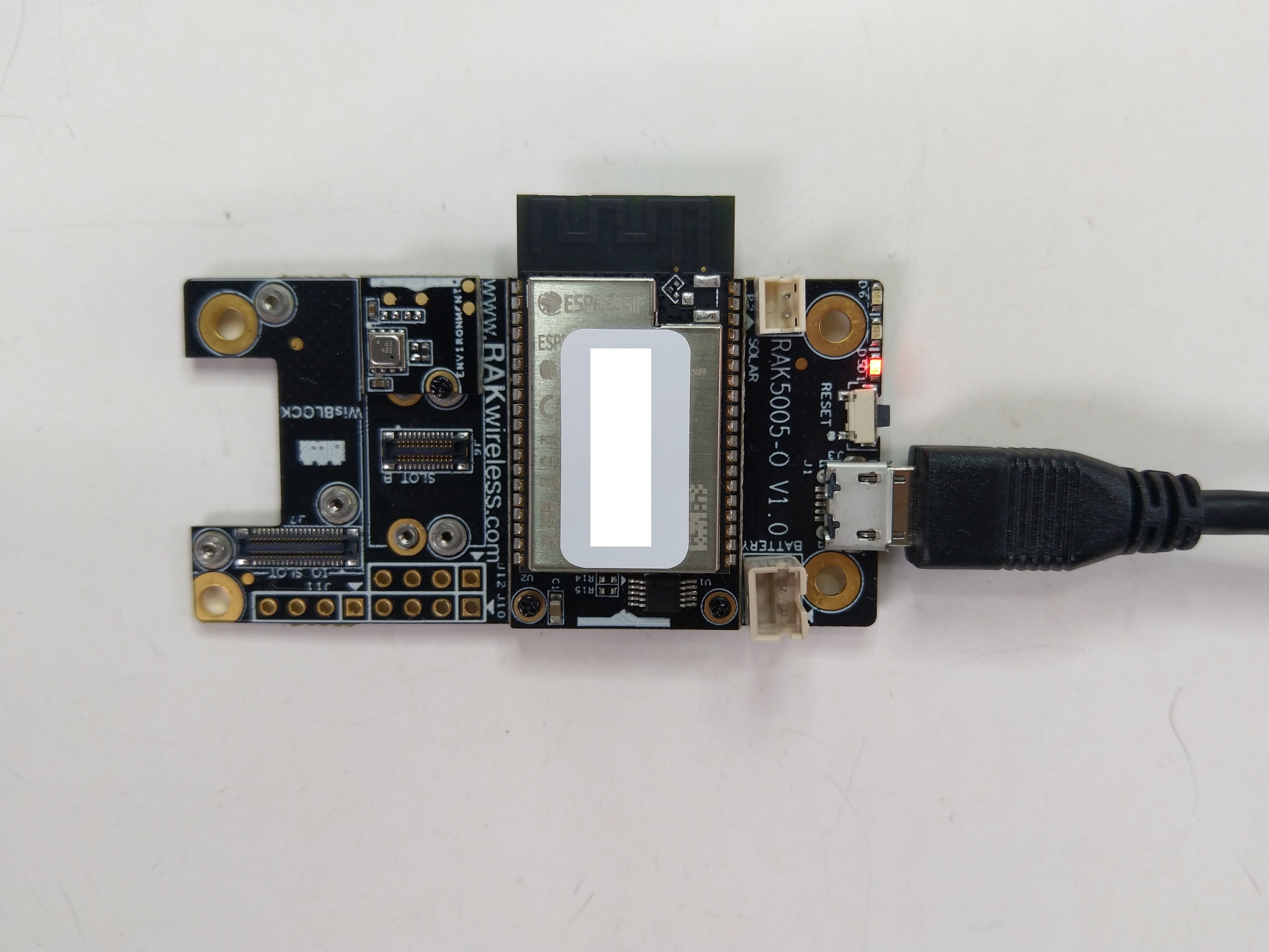
Reading the RAK1906 WisBlock Environment Sensor/BME680 GasResistance was failing randomly so I decided to dig a bit deeper. I checked the termination resistors, made sure the sensor was firmly seated on the RAK5005, and tried another Inter-Integrated Circuit(I²C) device on the same physical port.

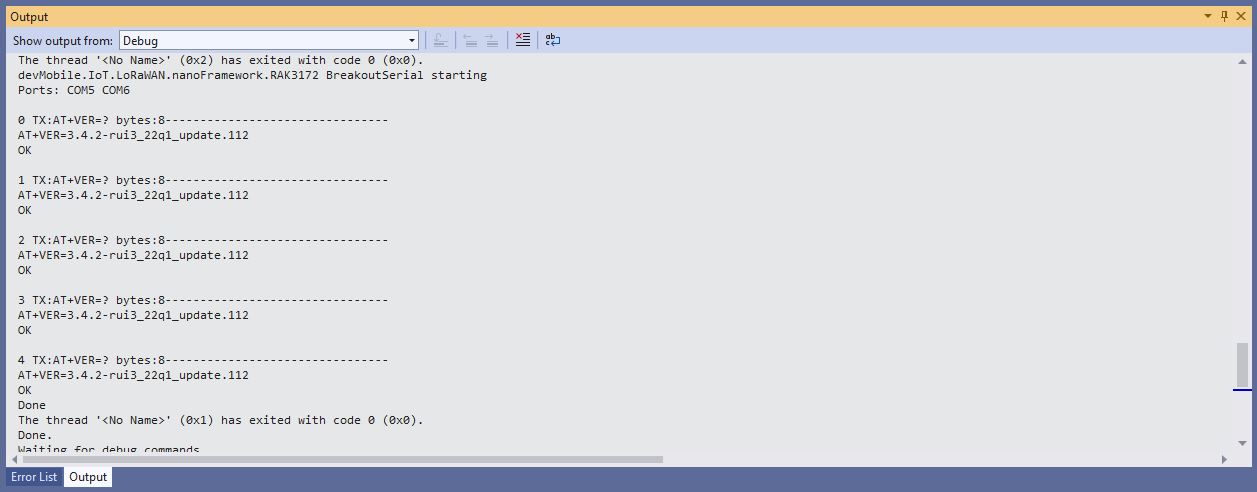
I then used Visual Studio 2022 Debugger to “single step” further into the BME680 code and the first thing that looked a bit odd was the TryReadTemperatureCore, TryReadPressureCore, TryReadHumidityCore and TryReadGasResistanceCore return values were ignored.
/// <summary>
/// Performs a synchronous reading.
/// </summary>
/// <returns><see cref="Bme680ReadResult"/></returns>
public Bme680ReadResult Read()
{
   SetPowerMode(Bme680PowerMode.Forced);
   Thread.Sleep((int)GetMeasurementDuration(HeaterProfile).Milliseconds);

    TryReadTemperatureCore(out Temperature temperature);
    TryReadPressureCore(out Pressure pressure, skipTempFineRead: true);
    TryReadHumidityCore(out RelativeHumidity humidity, skipTempFineRead: true);
    TryReadGasResistanceCore(out ElectricResistance gasResistance);

    return new Bme680ReadResult(temperature, pressure, humidity, gasResistance);
}
I then single stepped into the TryReadTemperatureCore which was returning a boolean indicating whether the read was success.
private bool TryReadTemperatureCore(out Temperature temperature)
{
    if (TemperatureSampling == Sampling.Skipped)
    {
        temperature = default;
        return false;
    }

    var temp = (int)Read24BitsFromRegister((byte)Bme680Register.TEMPDATA, Endianness.BigEndian);

    temperature = CompensateTemperature(temp >> 4);
    return true;
}
This library was based on the dotnet/iot Bmxx80 code, it looked similar, but I missed an important detail lots more ?’s…
Console.WriteLine("Hello BME680!");

// The I2C bus ID on the Raspberry Pi 3.
const int busId = 1;
// set this to the current sea level pressure in the area for correct altitude readings
Pressure defaultSeaLevelPressure = WeatherHelper.MeanSeaLevel;

I2cConnectionSettings i2cSettings = new(busId, Bme680.DefaultI2cAddress);
I2cDevice i2cDevice = I2cDevice.Create(i2cSettings);

using Bme680 bme680 = new Bme680(i2cDevice, Temperature.FromDegreesCelsius(20.0));

while (true)
{
    // reset will change settings back to default
    bme680.Reset();

    // 10 consecutive measurement with default settings
    for (var i = 0; i < 10; i++)
    {
        // Perform a synchronous measurement
        var readResult = bme680.Read();

        // Print out the measured data
        Console.WriteLine($"Gas resistance: {readResult.GasResistance?.Ohms:0.##}Ohm");
        Console.WriteLine($"Temperature: {readResult.Temperature?.DegreesCelsius:0.#}\u00B0C");
        Console.WriteLine($"Pressure: {readResult.Pressure?.Hectopascals:0.##}hPa");
        Console.WriteLine($"Relative humidity: {readResult.Humidity?.Percent:0.#}%");

        if (readResult.Temperature.HasValue && readResult.Pressure.HasValue)
        {
            var altValue = WeatherHelper.CalculateAltitude(readResult.Pressure.Value, defaultSeaLevelPressure, readResult.Temperature.Value);
            Console.WriteLine($"Altitude: {altValue.Meters:0.##}m");
        }

        if (readResult.Temperature.HasValue && readResult.Humidity.HasValue)
        {
            // WeatherHelper supports more calculations, such as saturated vapor pressure, actual vapor pressure and absolute humidity.
            Console.WriteLine($"Heat index: {WeatherHelper.CalculateHeatIndex(readResult.Temperature.Value, readResult.Humidity.Value).DegreesCelsius:0.#}\u00B0C");
            Console.WriteLine($"Dew point: {WeatherHelper.CalculateDewPoint(readResult.Temperature.Value, readResult.Humidity.Value).DegreesCelsius:0.#}\u00B0C");
        }

        // when measuring the gas resistance on each cycle it is important to wait a certain interval
        // because a heating plate is activated which will heat up the sensor without sleep, this can
        // falsify all readings coming from the sensor
        Thread.Sleep(1000);
    }
    ...
}
The Bme680 Read() method checked the TryReadTemperatureCore, TryReadPressureCore, TryReadHumidityCore & TryReadGasResistanceCore return values.
/// <summary>
/// Performs a synchronous reading.
/// </summary>
/// <returns><see cref="Bme680ReadResult"/></returns>
public Bme680ReadResult Read()
{
    SetPowerMode(Bme680PowerMode.Forced);
    Thread.Sleep((int)GetMeasurementDuration(HeaterProfile).Milliseconds);

    var tempSuccess = TryReadTemperatureCore(out var temperature);
    var pressSuccess = TryReadPressureCore(out var pressure, skipTempFineRead: true);
    var humiditySuccess = TryReadHumidityCore(out var humidity, skipTempFineRead: true);
    var gasSuccess = TryReadGasResistanceCore(out var gasResistance);

    return new Bme680ReadResult(tempSuccess ? temperature : null, pressSuccess ? pressure : null, humiditySuccess ? humidity : null, gasSuccess ? gasResistance : null);
}
The dotnet/iot Bmxx80 library uses Nullable reference types which are not supported by the nanoFramework(Sept 2022), and this was overlooked when the library was ported.
I have created a Github issue.