Arduino RS485 Temperature, Humidity & CO2 Sensor

As part of this series of samples comparing Arduino to nanoFramework to .NET IoT Device “Proof of Concept (PoC) applications, several posts use a SenseCAP CO2, Temperature and Humidity Sensor SKU101991029.

I cut up a spare Industrial IP68 Modbus RS485 1-to-4 Splitter/Hub to connect the sensor to the breakout board. This sensor has an operating voltage of 5V ~ 24V so it can be powered by the 5V output of a RS485 Breakout Board for Seeed Studio XIAO (SKU 113991354)

The red wire is for powering the sensor with a 12V power supply so was tied back so it didn’t touch any of the other electronics.

#include <HardwareSerial.h>
#include <ModbusMaster.h>

HardwareSerial RS485Serial(1);
ModbusMaster node;

// -----------------------------
// RS485 Pin Assignments (Corrected)
// -----------------------------
const int RS485_RX = 6;  // UART1 RX
const int RS485_TX = 5;  // UART1 TX
const int RS485_EN = D2;

// Sensor/Modbus parameters (from datasheet)
#define MODBUS_SLAVE_ID 0x2D
#define REG_CO2 0x0000
#define REG_TEMPERATURE 0x0001
#define REG_HUMIDITY 0x0002
#define REG_WARMUP_TIME 0x0021

uint32_t warmUp_Completed;

// Forward declarations for ModbusMaster callbacks
void preTransmission();
void postTransmission();

void setup() {
  Serial.begin(9600);
  delay(5000);

  Serial.println("ModbusMaster: Seeed SKU101991029 starting");

  // Wait for the hardware serial to be ready
  while (!Serial)
    ;
  Serial.println("Serial done");

  pinMode(RS485_EN, OUTPUT);
  digitalWrite(RS485_EN, LOW);  // Start in RX mode

  // Datasheet: 9600 baud, 8N1
  RS485Serial.begin(9600, SERIAL_8N1, RS485_RX, RS485_TX);
  while (!RS485Serial)
    ;
  Serial.println("RS485 done");

  // Tie ModbusMaster to the UART we just configured
  node.begin(MODBUS_SLAVE_ID, RS485Serial);

  // Register callbacks for half-duplex direction control
  node.preTransmission(preTransmission);
  node.postTransmission(postTransmission);

  // --- Read Startup time ---
  uint8_t result = node.readHoldingRegisters(REG_WARMUP_TIME, 1);
  if (result == node.ku8MBSuccess) {
    uint16_t warmUpTime = node.getResponseBuffer(0);
    warmUpTime += 3;
    Serial.printf("Start up time: %u sec\n", warmUpTime);
    warmUp_Completed = millis() + (warmUpTime * 1000);
  } else {
    Serial.printf("Read REG_WARMUP_TIME failed (err=%u)\n", result);
  }
}

// Toggle DE/RE around TX per ModbusMaster design
void preTransmission() {
  digitalWrite(RS485_EN, HIGH);  // enable driver (TX)
  delayMicroseconds(250);        // transceiver turn-around margin
}

void postTransmission() {
  delayMicroseconds(250);       // ensure last bit left the wire
  digitalWrite(RS485_EN, LOW);  // back to receive
}

void loop() {
  float temperature;
  uint16_t humidity;
  uint16_t co2;

  uint8_t result = node.readInputRegisters(0x0000, 3);

  if (result == node.ku8MBSuccess) {
    // --- Read Temperature ---
    uint16_t rawTemperature = node.getResponseBuffer(REG_TEMPERATURE);
    temperature = (int16_t)rawTemperature / 100.0;

    // --- Read Humidity ---
    humidity = node.getResponseBuffer(REG_HUMIDITY);
    humidity = humidity / 100;

    if (warmUp_Completed <= millis()) {
      // --- Read CO2  ---
      co2 = node.getResponseBuffer(REG_CO2);
      Serial.printf("Temperature: %.1f °C Humidity: %u %%RH CO2: %u ppm\n", temperature, humidity, co2);
    }
    else {
      Serial.printf("Temperature: %.1f °C Humidity: %u %%RH\n", temperature, humidity);
    }
  }
  else
  {
    Serial.printf("Modbus error: %d\n", result);      
  }

  delay(60000);
}

The Arduino ModbusMaster based application worked first time but implementing the CO2 Sensor warm-up time took a couple of attempts.

I did consider trying to fit the Seeed Studio XIAO ESP32-S3 inside the SenseCAP CO2, Temperature and Humidity Sensor but the electronics had been sprayed with a corrosion resistant coating.

Connecting directly (rather than via a breakout board) the VCC+, VCC-, universal asynchronous receiver-transmitter(UART) and transmit enable would have been difficult.

Arduino RS485 750cm Ultrasonic Level Sensor

The first couple of Proof of Concept(PoC) applications used a Seeedstudio SenseCAP RS485 500cm Ultrasonic Level Sensor (SKU 101991042). They also sell the SenseCAP RS485 750cm Ultrasonic Level Sensor which I found has exactly the same MODBUS interface setup.

Like the SenseCAP RS485 500cm Ultrasonic Level the SenseCAP RS485 750cm Ultrasonic Level Sensor has a Grove connector so the cable had to be “modified” before it would work with the RS485 Breakout Board for Seeed Studio XIAO (SKU 113991354).

The first step was to bend the crimp connector locks back using a very small screwdriver.

Then split the heat-shrink and cable outer, so the individual cables were longer.

The crimp connector at the of each wire had to be “modified” by trimming them with a pair of wire cutters (just in front of the crimped section) so that they could be inserted into the breakout board connectors.

The distance measurements were within a CM which was good. When I took the RS485 750cm Ultrasonic Level Sensor outside the distance returned was 0.0cm when the target was more 750cm away. I hadn’t noticed this with the Seeedstudio RS485 500cm Ultrasonic Level Sensor (SKU 101991042) as the ceiling in my office only 1.9M above the surface of my desk.

nanoFramework RS485 Temperature, Humidity & CO2 Sensor

As part of this series of samples comparing Arduino to nanoFramework to .NET IoT Device “Proof of Concept (PoC) applications, several posts use a SenseCAP CO2, Temperature and Humidity Sensor SKU101991029.

I cut one of the cables of a spare Industrial IP68 Modbus RS485 1-to-4 Splitter/Hub to connect the sensor to the breakout board. This sensor has an operating voltage of 5V ~ 24V so it can be powered by the 5V output of a RS485 Breakout Board for Seeed Studio XIAO (SKU 113991354)

The red wire is for powering the sensor with a 12V power supply so was tied back so it didn’t touch any of the other electronics.

public static void Main()
{
   Debug.WriteLine("Modbus Client for Seeedstudio Temperature Humidity and CO2 sensor SKU101991029");

   Configuration.SetPinFunction(Gpio.IO06, DeviceFunction.COM2_RX);
   Configuration.SetPinFunction(Gpio.IO05, DeviceFunction.COM2_TX);
   Configuration.SetPinFunction(Gpio.IO03, DeviceFunction.COM2_RTS);

   DateTime warmupCompleted = DateTime.UtcNow;

   // Modbus Client
   using (var client = new ModbusClient("COM2"))
   {
      try
      {
         Debug.WriteLine("Reading CO2 Sensor Warmup duration");

         // Read warm-up time (seconds) from 0x0021
         var warmupReg = client.ReadHoldingRegisters(SlaveAddress, RegWarmup, 1);
         ushort warmupSeconds = unchecked((ushort)warmupReg[0]);

         Debug.WriteLine($"Sensor warm-up:{warmupSeconds}sec");

         warmupCompleted += TimeSpan.FromSeconds(warmupSeconds);
      }
      catch (Exception ex)
      {
         Debug.WriteLine($"Warm-up read failed (continuing): {ex.Message}");
      }

      while (true)
      {
         try
         {
            var regs = client.ReadHoldingRegisters(SlaveAddress, RegCO2, 3);
            short rawTemp = regs[RegTemperature];
            double tempC = rawTemp / 100.0; // Signed 16 - bit, value = °C * 100

            // regs[2] = Humidity. Unsigned 16-bit, value = %RH * 100
            ushort rawRh = unchecked((ushort)regs[RegHumidity]);
            double rhPercent = rawRh / 100.0; // Humidity. Unsigned 16-bit, value = %RH * 100

            if (DateTime.UtcNow > warmupCompleted)
            {
               // regs[0] = CO2 (ppm)
               ushort rawCO2 = unchecked((ushort)regs[RegCO2]);

               int co2Ppm = rawCO2; // already ppm
               Debug.WriteLine($"T:{tempC:F2}°C, RH:{rhPercent:F2}%, CO2:{co2Ppm} ppm");
            }
            else
            {
               Debug.WriteLine($"T:{tempC:F2}°C, RH:{rhPercent:F2}%");
            }
         }
         catch (Exception ex)
         {
            Debug.WriteLine($"Read failed: {ex.Message}");
         }

         Thread.Sleep(60000);
      }
   }
}

The nanoFramework Modbus Library based application worked first time but implementing the CO2 Sensor warm-up time took a couple of attempts.

I did consider trying to fit the Seeed Studio XIAO ESP32-S3 inside the SenseCAP CO2, Temperature and Humidity Sensor but the electronics had been sprayed with a corrosion resistant coating. Connecting (rather than via a breakout board) the VCC+, VCC-, universal asynchronous receiver-transmitter(UART) and transmit enable would have been difficult.

I tried Copilot to clean up the image but it didn’t go well

Azure Event Grid esp-mqtt-arduino Client – Transient fail

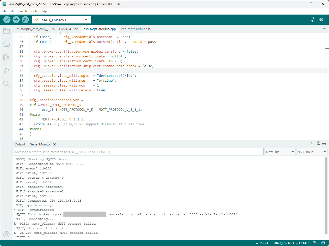
I couldn’t figure out why my code was failing so I gave up. Then the following day the application worked which was really odd. I then fired up my original Arduino PubSubClient library based application to do some testing and went to make a coffee. The application was failing to connect as XiaoTandHandCO2A and even when the bug was fixed (last will setup configuration commented out) it still wouldn’t connect.

The Azure EventGrid MQTT Broker client configuration looked fine

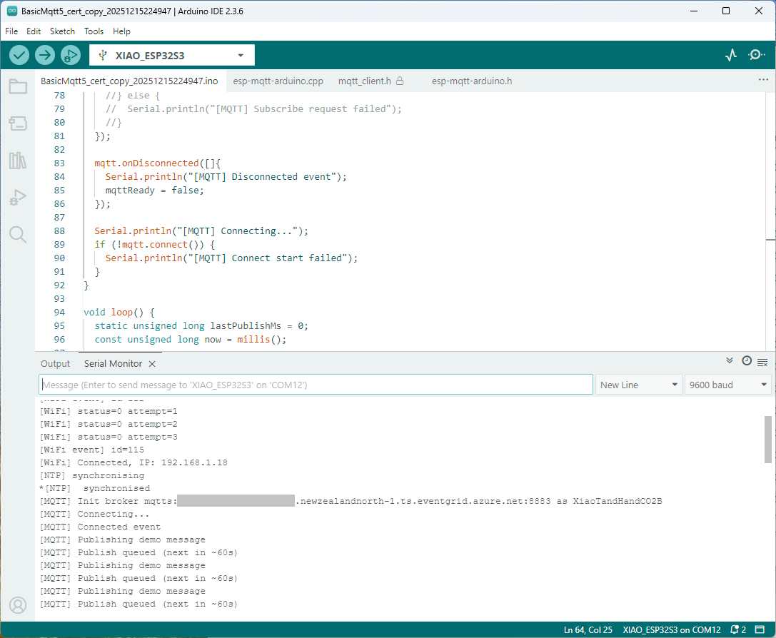
Accidentally the configuration was changed XiaoTandHandCO2B and the application worked which was unexpected. I still couldn’t figure out why my code was failing XiaoTandHandCO2A so I gave up.

The following morning the XiaoTandHandCO2A configuration worked which was a bit odd. My best guess is that after a number of failed attempts the device is “disabled” for a while (but this is not displayed in the client configuration) and the following morning enough time had passed for the device to be “re-enabled”.

For testing I usually split my constants & secrets into two files, constants has the certificate chains for the Azure Event Grid MQTT Broker and secrets has certificate chains for devices and the Azure EventGrid MQTT Broker. I did consider have a secrets.h file for each device or splitting the device intermediate certificates, but as I was debugging and testing, it was just easier to duplicate them.

// constants.h
#pragma once

const uint16_t MQTT_PORT = 8883;

// This certificate is used to authenticate the host
static const char CA_ROOT_PEM[] PROGMEM = R"PEM(
-----BEGIN CERTIFICATE-----
...
-----END CERTIFICATE-----
-----BEGIN CERTIFICATE-----
...
-----END CERTIFICATE-----
)PEM";

// Secrets.h
#pragma once

// Wi-Fi credentials
const char* WIFI_SSID = "SSID";
const char* WIFI_PASSWORD = "Password";

// MQTT settings
//const char* MQTT_SERVER_URI = "MyBroker.newzealandnorth-1.ts.eventgrid.azure.net";
const char* MQTT_SERVER_URL = "mqtts://MyBroker.newzealandnorth-1.ts.eventgrid.azure.net:8883";

/*
// This is A setup, below are B, C, D, & E
const char* MQTT_CLIENTID = "XiaoTandHandCO2A";
const char* MQTT_TOPIC_PUBLISH = "devices/XiaoTandHandCO2A/sequence"; 
const char* MQTT_TOPIC_SUBSCRIBE = "devices/XiaoTandHandCO2A/configuration"; 

static const char CLIENT_CERT_PEM[] PROGMEM = R"PEM(
-----BEGIN CERTIFICATE-----
-----END CERTIFICATE-----
-----BEGIN CERTIFICATE-----
Intermediate certificate
-----END CERTIFICATE-----
)PEM";

static const char CLIENT_KEY_PEM[] PROGMEM = R"PEM(
-----BEGIN PRIVATE KEY-----
-----END PRIVATE KEY-----
)PEM";
*/

const char* MQTT_CLIENTID = "XiaoTandHandCO2B"; 
const char* MQTT_TOPIC_PUBLISH = "devices/XiaoTandHandCO2B/sequence"; 
const char* MQTT_TOPIC_SUBSCRIBE = "devices/XiaoTandHandCO2V/configuration"; 

static const char CLIENT_CERT_PEM[] PROGMEM = R"PEM(
-----BEGIN CERTIFICATE-----
-----END CERTIFICATE-----
-----BEGIN CERTIFICATE-----
Intermediate certificate
-----END CERTIFICATE-----
)PEM";

static const char CLIENT_KEY_PEM[] PROGMEM = R"PEM(
-----BEGIN PRIVATE KEY-----
-----END PRIVATE KEY-----
)PEM";

/*
const char* MQTT_CLIENTID = "XiaoTandHandCO2C"; 
const char* MQTT_TOPIC_PUBLISH = "devices/XiaoTandHandCO2C/sequence"; 
const char* MQTT_TOPIC_SUBSCRIBE = "devices/XiaoTandHandCO2V/configuration"; 

static const char CLIENT_CERT_PEM[] PROGMEM = R"PEM(
-----BEGIN CERTIFICATE-----
-----END CERTIFICATE-----
-----BEGIN CERTIFICATE-----
Intermediate certificate
-----END CERTIFICATE-----
)PEM";

static const char CLIENT_KEY_PEM[] PROGMEM = R"PEM(
-----BEGIN PRIVATE KEY-----
-----END PRIVATE KEY-----
)PEM";
*/

/*
const char* MQTT_CLIENTID = "XiaoTandHandCO2D"; 
const char* MQTT_TOPIC_PUBLISH = "devices/XiaoTandHandCO2D/sequence"; 
const char* MQTT_TOPIC_SUBSCRIBE = "devices/XiaoTandHandCO2V/configuration"; 

static const char CLIENT_CERT_PEM[] PROGMEM = R"PEM(
-----BEGIN CERTIFICATE-----
-----END CERTIFICATE-----
-----BEGIN CERTIFICATE-----
Intermediate certificate
-----END CERTIFICATE-----
)PEM";

static const char CLIENT_KEY_PEM[] PROGMEM = R"PEM(
-----BEGIN PRIVATE KEY-----
-----END PRIVATE KEY-----
)PEM";
*/

/*
const char* MQTT_CLIENTID = "XiaoTandHandCO2E"; 
const char* MQTT_TOPIC_PUBLISH = "devices/XiaoTandHandCO2E/sequence"; 
const char* MQTT_TOPIC_SUBSCRIBE = "devices/XiaoTandHandCO2V/configuration"; 

static const char CLIENT_CERT_PEM[] PROGMEM = R"PEM(
-----BEGIN CERTIFICATE-----
-----END CERTIFICATE-----
-----BEGIN CERTIFICATE-----
Intermediate certificate
-----END CERTIFICATE-----
)PEM";

static const char CLIENT_KEY_PEM[] PROGMEM = R"PEM(
-----BEGIN PRIVATE KEY-----
-----END PRIVATE KEY-----
)PEM";
*/

To make deployments easier I have some software which stores the certificates in an optional “secure element” like the Microchip ATECC608C(The Seeedstudio Edgebox100 documentation refers to an optional Microchip ATECC680A but these are “not recommended for new designs”). This isn’t a great solution but deployments easier and is “better” than a string constant in the binary.

nanoFramework RS485 500cm Ultrasonic Level Sensor

As part of this series of samples comparing Arduino to nanoFramework to .NET IoT Device “Proof of Concept (PoC) applications, the next couple of posts use an RS485 500cm Ultrasonic Level Sensor (SKU 101991042). I started with this sensor because its uses Modbus and has an operating voltage of 3.3~24 V so it can be powered by the 5V output of a RS485 Breakout Board for Seeed Studio XIAO (SKU 113991354)

Initially the nanoFramework Modbus Library based application didn’t work but after correcting the pin assignments based on the Seeedstudio XIAO ESP32 S3 RS-485 test harness(nanoFramework) reading one sensor value worked reliably.

// XIAO ESP32S3 + RS485 breakout + Seeed 101991042 (RS-485 Modbus RTU)
// Reads: 0x0100 (calculated distance, mm), 0x0101 (real-time distance, mm),
//        0x0102 (temperature, 0.1°C). Can write 0x0200 (slave address).
// Serial: 9600 8N1 per datasheet. (Default slave addr = 0x01)

//Iot.Device.Modbus (namespace Iot.Device.Modbus.Client)
//using Iot.Device.Modbus;
using Iot.Device.Modbus.Client;
//using Microsoft.Extensions.Logging;
using nanoFramework.Hardware.Esp32;
//using nanoFramework.Logging.Debug;
using System;
using System.Diagnostics;
using System.IO.Ports;
using System.Threading;


namespace SeeedRS485500cmUltrasonicLevelSensor
{
   public class Program
   {
      // === Sensor Modbus params (from Seeed datasheet) ===
      private const byte SlaveAddress = 0x01;      // default
      private const ushort RegCalcDistance = 0x0100;// mm, ~500ms processing
      //private const ushort RegRealDistance = 0x0101;// mm, ~100ms
      private const ushort RegTemperature = 0x0102;// INT16, 0.1°C units
      private const ushort RegSlaveAddress = 0x0200;// R/W address register

      public static void Main()
      {
         ModbusClient _client;

         Console.WriteLine("Modbus: Seeed SKU101991042 Starting");

         Configuration.SetPinFunction(Gpio.IO06, DeviceFunction.COM2_RX);
         Configuration.SetPinFunction(Gpio.IO05, DeviceFunction.COM2_TX);
         // This port number is a bit weird, need to double check in RS485 Sender/Receiver apps
         Configuration.SetPinFunction(Gpio.IO03, DeviceFunction.COM2_RTS); 

         var ports = SerialPort.GetPortNames();

         Debug.WriteLine("Available ports: ");
         foreach (string port in ports)
         {
            Debug.WriteLine($" {port}");
         }

         using (_client = new ModbusClient("COM2"))
         {
            _client.ReadTimeout = _client.WriteTimeout = 2000;

            //_client.Logger = new DebugLogger("ModbusClient") 
            //{ 
            //   MinLogLevel = LogLevel.Debug 
            //};

            while (true)
            {
               try
               {
                   // 0x0100 Calculated distance (mm). Takes ~500ms to compute per datasheet.
                  short[] calc = _client.ReadHoldingRegisters(SlaveAddress, RegCalcDistance, 1);
                  ushort calcMm = (ushort)calc[0];
                  float calcCm = calcMm / 10.0f;
                  Console.WriteLine($"Calculated distance: {calcMm} mm ({calcCm:F1} cm)");

                  /*
                  // 0x0101 Real-time distance (mm). Faster ~100ms response.
                  short[] real = _client.ReadHoldingRegisters(SlaveAddress, RegRealDistance, 1);
                  short realMm = real[0];
                  float realCm = realMm / 10.0f;
                  Console.WriteLine($"Real-time distance:  {realMm} mm ({realCm:F1} cm)");
                  */

                  // 0x0102 Temperature (INT16, 0.1°C)
                  short[] temp = _client.ReadHoldingRegisters(SlaveAddress, RegTemperature, 1);
                  short tempRaw = unchecked((short)temp[0]); // signed per datasheet
                  float tempC = tempRaw / 10.0f;
                  Console.WriteLine($"Temperature: {tempC:F1} °C");
               }
               catch (Exception ex)
               {
                  Console.WriteLine($"Modbus read failed: {ex.Message}");
               }

               Thread.Sleep(10000);
            }
         }
      }
   }
}

The nanoFramework logging support made debugging connectivity issues much faster. So much so I started with the nanoFramework application then progressed to the Arduino version.

I had to add a short delay between each Modbus sensor value read to stop timeout errors.

Arduino RS485 500cm Ultrasonic Level Sensor

As part of this series of samples comparing Arduino to nanoFramework to .NET IoT Device “Proof of Concept (PoC) applications, the next couple of posts use an RS485 500cm Ultrasonic Level Sensor (SKU 101991042). I started with this sensor because its uses MODBUS and has an operating voltage of 3.3~24 V so it can be powered by the 5V output of a RS485 Breakout Board for Seeed Studio XIAO (SKU 113991354)

Initially the ModBusMaster based application didn’t work but after correcting the pin assignments based on the Seeedstudio XIAO ESP32 S3 RS-485 test harness(Arduino) reading one sensor worked reliably.

#include <HardwareSerial.h>
#include <ModbusMaster.h>

HardwareSerial RS485Serial(1);
ModbusMaster node;

// Pin mapping for XIAO RS485 breakout
const int RS485_RX = 6;   // UART1 RX
const int RS485_TX = 5;   // UART1 TX
const int RS485_EN = D2;   // DE/RE control (single pin)

// Sensor/Modbus parameters (from datasheet)
const uint8_t  SLAVE_ADDR = 0x01;        // default address
const uint16_t REG_CALC_DISTANCE = 0x0100;
//const uint16_t REG_REAL_DISTANCE = 0x0101;
const uint16_t REG_TEMPERATURE   = 0x0102;
const uint16_t REG_SLAVE_ADDR    = 0x0200;

// Forward declarations for ModbusMaster callbacks
void preTransmission();
void postTransmission();

void setup() {
  Serial.begin(9600);
  delay(5000);
  Serial.println("ModbusMaster: Seeed SKU101991042 Starting");

 // Wait for the hardware serial to be ready
  while (!Serial)
    ;
  Serial.println("Serial done");

  // RS485 transceiver enable pin
  pinMode(RS485_EN, OUTPUT);
  digitalWrite(RS485_EN, LOW);           // start in RX mode

  // Datasheet: 9600 baud, 8N1
  RS485Serial.begin(9600, SERIAL_8N1, RS485_RX, RS485_TX);
  while (!RS485Serial)
    ;
  Serial.println("RS485 done");

  // Tie ModbusMaster to the UART we just configured
  node.begin(SLAVE_ADDR, RS485Serial);

  // Register callbacks for half-duplex direction control
  node.preTransmission(preTransmission);
  node.postTransmission(postTransmission);

  Serial.println("ModbusMaster: Seeed 101991042 distance & temperature reader ready.");
}

// Toggle DE/RE around TX per ModbusMaster design
void preTransmission() {
  digitalWrite(RS485_EN, HIGH);          // enable driver (TX)
  delayMicroseconds(250);                // transceiver turn-around margin
}

void postTransmission() {
  delayMicroseconds(250);                // ensure last bit left the wire
  digitalWrite(RS485_EN, LOW);           // back to receive
}

void loop() {
  static uint32_t last = 0;
  //if (millis() - last >= 1000) {         // poll at 1 Hz
  if (millis() - last >= 360000) {         // poll at 0.2 Hz
    last = millis();

    // --- 0x0100 Calculated distance (mm) ---
    uint8_t result = node.readHoldingRegisters(REG_CALC_DISTANCE, 1);
    if (result == node.ku8MBSuccess) {
      uint16_t dist_calc_mm = node.getResponseBuffer(0); // big-endian per Modbus
      float dist_calc_cm = dist_calc_mm / 10.0f;
      Serial.printf("Calculated distance: %u mm (%.1f cm)\n", dist_calc_mm, dist_calc_cm);
    } else {
      Serial.printf("Read 0x0100 failed (err=%u)\n", result);
    }
    delay(1000);
/*
    // --- 0x0101 Real-time distance (mm) ---
    result = node.readHoldingRegisters(REG_REAL_DISTANCE, 1);
    if (result == node.ku8MBSuccess) {
      uint16_t dist_real_mm = node.getResponseBuffer(0);
      float dist_real_cm = dist_real_mm / 10.0f;
      Serial.printf("Real-time distance:  %u mm (%.1f cm)\n", dist_real_mm, dist_real_cm);
    } else {
      Serial.printf("Read 0x0101 failed (err=%u)\n", result);
    }
*/
    // --- 0x0102 Temperature (INT16, 0.1°C) ---
    result = node.readHoldingRegisters(REG_TEMPERATURE, 1);
    if (result == node.ku8MBSuccess) {
      uint16_t raw = node.getResponseBuffer(0);
      int16_t temp_i16 = (int16_t)raw;
      float temp_c = temp_i16 / 10.0f;
      Serial.printf("Temperature: %.1f °C\n", temp_c);
    } else {
      Serial.printf("Read 0x0102 failed (err=%u)\n", result);
    }
    delay(1000);
  }
}

I had to add a short delay between each MODBUS sensor read to stop timeout errors.

Seeedstudio XIAO ESP32 S3 RS-485 test harness(nanoFramework)

As part of a project to read values from a MODBUS RS-485 sensor using a RS-485 Breakout Board for Seeed Studio XIAO and a Seeed Studio XIAO ESP32-S3 I built a .NET nanoFramework version of the Arduino test harness described in this wiki post.

This took a bit longer than I expected mainly because running two instances of Visual Studio 2026 was a problem (running Visual Studio 2022 for one device and Visual Studio 2026 for the other, though not 100% confident this was an issue) as there were some weird interactions.

using nanoff to flash a device with the latest version of ESP32_S3_ALL_UART

As I moved between the Arduino tooling and flashing devices with nanoff the serial port numbers would change watching the port assignments in Windows Device Manager was key.

Windows Device manager displaying the available serial ports

Rather than debugging both the nanoFramework RS485Sender and RS485Receiver applications simultaneously, I used the Arduino RS485Sender and RS485 Receiver application but had similar issues with the port assignments changing.

Arduino RS485 Sender application
The nanoFramework sender application
public class Program
{
   static SerialPort _serialDevice;

   public static void Main()
   {
      Configuration.SetPinFunction(Gpio.IO06, DeviceFunction.COM2_RX);
      Configuration.SetPinFunction(Gpio.IO05, DeviceFunction.COM2_TX);
      Configuration.SetPinFunction(Gpio.IO02, DeviceFunction.COM2_RTS);

      Debug.WriteLine("RS485 Sender: ");

      var ports = SerialPort.GetPortNames();

      Debug.WriteLine("Available ports: ");
      foreach (string port in ports)
      {
         Debug.WriteLine($" {port}");
      }

      _serialDevice = new SerialPort("COM2");
      _serialDevice.BaudRate = 9600;
      _serialDevice.Mode = SerialMode.RS485;

      _serialDevice.Open();

      Debug.WriteLine("Sending...");
      while (true)
      {
         string payload = $"{DateTime.UtcNow:HHmmss}";

         Debug.WriteLine($"Sent:{DateTime.UtcNow:HHmmss}");

         Debug.WriteLine(payload);

         _serialDevice.WriteLine(payload);

         Thread.Sleep(2000);
      }
   }
}

if I had built the nanoFramework RS485Sender and RS485Receiver applications first debugging the Arduino RS485Sender and RS485Receiver would been similar.

Arduino receiver application displaying messages from the nanoFramework sender application
The nanoFramework Receiver receiving messages from the nanoFramework Sender
public class Program
{
   static SerialPort _serialDevice ;
 
   public static void Main()
   {
      Configuration.SetPinFunction(Gpio.IO06, DeviceFunction.COM2_RX);
      Configuration.SetPinFunction(Gpio.IO05, DeviceFunction.COM2_TX);
      Configuration.SetPinFunction(Gpio.IO02, DeviceFunction.COM2_RTS);

      Debug.WriteLine("RS485 Receiver ");

      // get available ports
      var ports = SerialPort.GetPortNames();

      Debug.WriteLine("Available ports: ");
      foreach (string port in ports)
      {
         Debug.WriteLine($" {port}");
      }

      // set parameters
      _serialDevice = new SerialPort("COM2");
      _serialDevice.BaudRate = 9600;
      _serialDevice.Mode = SerialMode.RS485;

      // set a watch char to be notified when it's available in the input stream
      _serialDevice.WatchChar = '\n';

      // setup an event handler that will fire when a char is received in the serial device input stream
      _serialDevice.DataReceived += SerialDevice_DataReceived;

      _serialDevice.Open();

      Debug.WriteLine("Waiting...");
      Thread.Sleep(Timeout.Infinite);
   }

   private static void SerialDevice_DataReceived(object sender, SerialDataReceivedEventArgs e)
   {
      SerialPort serialDevice = (SerialPort)sender;

      switch (e.EventType)
      {
         case SerialData.Chars:
         //break;

         case SerialData.WatchChar:
            string response = serialDevice.ReadExisting();
            Debug.Write($"Received:{response}");
            break;
         default:
            Debug.Assert(false, $"e.EventType {e.EventType} unknown");
            break;
      }
   }
}

The changing of serial port numbers while running different combinations of Arduino and nanoFramework environments concurrently combined with the sender and receiver applications having to be deployed to the right devices (also initially accidentally different baud rates) was a word of pain, and with the benefit of hindsight I should have used two computers.

Azure Event Grid nanoFramework Client – Publisher

Building a .NET nanoFramework application for testing Azure Event Grid MQTT Broker connectivity that would run on my Seeedstudio EdgeBox ESP100 and Seeedstudio Xiao ESP32S3 devices took a couple of hours. Most of that time was spent figuring out how to generate the certificate and elliptic curve private key

Create an elliptic curve private key

 openssl ecparam -name prime256v1 -genkey -noout -out device.key

Generate a certificate signing request

openssl req -new -key device.key -out device.csr -subj "/CN=device.example.com/O=YourOrg/OU=IoT"

Then use the intermediate certificate and key file from earlier to generate a device certificate and key.

 openssl x509 -req -in device.csr -CA IntermediateCA.crt -CAkey IntermediateCA.key -CAcreateserial -out device.crt -days 365 -sha256

In this post I have assumed that the reader is familiar with configuring Azure Event Grid clients, client groups, topic spaces, permission bindings and routing.

The PEM encoded root CA certificate chain that is used to validate the server
public const string CA_ROOT_PEM = @"-----BEGIN CERTIFICATE-----
CN: CN = Microsoft Azure ECC TLS Issuing CA 03
-----END CERTIFICATE-----
-----BEGIN CERTIFICATE-----
CN: CN = DigiCert Global Root G3
-----END CERTIFICATE-----";

The PEM encoded certificate chain that is used to authenticate the device
public const string CLIENT_CERT_PEM_A = @"-----BEGIN CERTIFICATE-----
-----BEGIN CERTIFICATE-----
 CN=Self signed device certificate
-----END CERTIFICATE-----
-----BEGIN CERTIFICATE-----
 CN=Self signed Intermediate certificate
-----END CERTIFICATE-----";

 The PEM encoded private key of device
public const string CLIENT_KEY_PEM_A = @"-----BEGIN EC PRIVATE KEY-----
-----END EC PRIVATE KEY-----";

My application was “inspired” by the .NET nanoFramework m2mqtt example.

public static void Main()
{
   int sequenceNumber = 0;
   MqttClient mqttClient = null;
   Thread.Sleep(1000); // Found this works around some issues with running immediately after a reset

   bool wifiConnected = false;
   Console.WriteLine("WiFi connecting...");
   do
   {
      // Attempt to connect using DHCP
      wifiConnected = WifiNetworkHelper.ConnectDhcp(Secrets.WIFI_SSID, Secrets.WIFI_PASSWORD, requiresDateTime: true);

      if (!wifiConnected)
      {
         Console.WriteLine($"Failed to connect. Error: {WifiNetworkHelper.Status}");
         if (WifiNetworkHelper.HelperException != null)
         {
            Console.WriteLine($"Exception: {WifiNetworkHelper.HelperException}");
         }

         Thread.Sleep(1000);
      }
   }
   while (!wifiConnected);
   Console.WriteLine("WiFi connected");

   var caCert = new X509Certificate(Constants.CA_ROOT_PEM);

   X509Certificate2 clientCert = null;
   try
   {
      clientCert = new X509Certificate2(Secrets.CLIENT_CERT_PEM_A, Secrets.CLIENT_KEY_PEM_A, string.Empty);
   }
   catch (Exception ex)
   {
      Console.WriteLine($"Client Certificate Exception: {ex.Message}");
   }

   mqttClient = new MqttClient(Secrets.MQTT_SERVER, Constants.MQTT_PORT, true, caCert, clientCert, MqttSslProtocols.TLSv1_2);

   mqttClient.ProtocolVersion = MqttProtocolVersion.Version_5;

   bool mqttConnected = false;
   Console.WriteLine("MQTT connecting...");
   do
   {
      try
      {
         // Regular connect
         var resultConnect = mqttClient.Connect(Secrets.MQTT_CLIENTID, Secrets.MQTT_USERNAME, Secrets.MQTT_PASSWORD);
         if (resultConnect != MqttReasonCode.Success)
         {
            Console.WriteLine($"MQTT ERROR connecting: {resultConnect}");
            Thread.Sleep(1000);
         }
         else
         {
            mqttConnected = true;
         }
      }
      catch (Exception ex)
      {
         Console.WriteLine($"MQTT ERROR Exception '{ex.Message}'");
         Thread.Sleep(1000);
      }
   }
   while (!mqttConnected);
   Console.WriteLine("MQTT connected...");

   mqttClient.MqttMsgPublishReceived += MqttMsgPublishReceived;
   mqttClient.MqttMsgSubscribed += MqttMsgSubscribed;
   mqttClient.MqttMsgUnsubscribed += MqttMsgUnsubscribed;
   mqttClient.ConnectionOpened += ConnectionOpened;
   mqttClient.ConnectionClosed += ConnectionClosed;
   mqttClient.ConnectionClosedRequest += ConnectionClosedRequest;

   string topicPublish = string.Format(MQTT_TOPIC_PUBLISH_FORMAT, Secrets.MQTT_CLIENTID);
   while (true)
   {
      Console.WriteLine("MQTT publish message start...");

      var payload = new MessagePayload() { ClientID = Secrets.MQTT_CLIENTID, Sequence = sequenceNumber++ };

      string jsonPayload = JsonSerializer.SerializeObject(payload);

      var result = mqttClient.Publish(topicPublish, Encoding.UTF8.GetBytes(jsonPayload), "application/json; charset=utf-8", null);

      Debug.WriteLine($"MQTT published ({result}): {jsonPayload}");

      Thread.Sleep(100);
   }
}

I then configured my client (Edgebox100Z) and updated the “secrets.cs” file

Azure Event Grid MQTT Broker Clients

The application connected to the Azure Event Grid MQTT broker and started publishing the JSON payload with the incrementing sequence number.

Visual Studio debugger output of JSON payload publishing

The published messages were “routed” to an Azure Storage Queue where they could be inspected with a tool like Azure Storage Explorer.

Azure Event Grid MQTT Broker metrics with messages published selected

I could see the application was working in the Azure Event Grid MQTT broker metrics because the number of messages published was increasing.

Seeedstudio XIAO ESP32 S3 RS-485 test harness(Arduino)

As part of a project to read values from a MODBUS RS-485 sensor using a RS-485 Breakout Board for Seeed Studio XIAO and a Seeed Studio XIAO ESP32-S3 I built the test harness described in the wiki post. The test harness setup for a Seeed Studio XIAO ESP32-C3/Seeed Studio XIAO ESP32-C6 didn’t work with my Seeed Studio XIAO ESP32-S3.

I then did some digging looked at schematics and figured out the port mappings were different. This took a while so I tried Microsoft Copilot

I then updated the port assigned for my RS485Sender application

#include <HardwareSerial.h>

HardwareSerial RS485(1);

#define enable_pin D2

void setup() {
  Serial.begin(9600);  // Initialize the hardware serial with a baud rate of 115200
  delay(5000);

  Serial.println("RS485 Sender");

  // Wait for the hardware serial to be ready
  while (!Serial)
    ;
  Serial.println("!Serial done");

  //mySerial.begin(115200, SERIAL_8N1, 7, 6); // RX=D4(GPIO6), TX=D5(GPIO7) Doesn't work
  RS485.begin(115200, SERIAL_8N1, 6, 5);

  // Wait for the hardware serial to be ready
  while (!RS485)
    ;
  Serial.println("!RS485 done ");

  pinMode(enable_pin, OUTPUT);     // Set the enable pin as an output
  digitalWrite(enable_pin, HIGH);  // Set the enable pin to high
}

void loop() {
  if (Serial.available()) {
    String inputData = Serial.readStringUntil('\n');  // Read the data from the hardware serial until a newline character

    // If the received data is not empty
    if (inputData.length() > 0) {
      Serial.println("Send successfully");  // Print a success message
      RS485.println(inputData);             // Send the received data to the hardware serial
    }
  }
}

I then updated the port assigned for my RS485Receiver application

#include <HardwareSerial.h>

HardwareSerial RS485(1);  // Use UART2
#define enable_pin D2

void setup() {
  Serial.begin(9600);  // Initialize the hardware serial with a baud rate of 115200
  delay(5000);

  Serial.println("RS485 Receiver");

  // Wait for the hardware serial to be ready
  while (!Serial)
    ;
  Serial.println("!Serial done");

  // mySerial.begin(115200, SERIAL_8N1, 7, 6); // RX=D4(GPIO6), TX=D5(GPIO7) Doesn't seem to work
  RS485.begin(115200, SERIAL_8N1, 6, 5); 
  
    // Wait for the hardware serial to be ready
  while (!RS485)
    ;
  Serial.println("!RS485 done ");

  pinMode(enable_pin, OUTPUT);    // Set the enable pin as an output
  digitalWrite(enable_pin, LOW);  // Set the enable pin to low
}

void loop() {
  // Check if there is data available from the hardware serial
  int x = RS485.available();

  if (x) {
    String response = RS485.readString();

    Serial.println(" RS485 Response: " + response);
  }

  delay(1000);
}

Getting my test harness RS485Sender and RS485Receiver applications (inspired by Seeedstudio wiki) took quite a bit longer than expected. Using Copilot worked better than expected but I think that might be because after doing some research my prompts were better.

RTSP Camera Nager.VideoStream Startup Latency

While working on my RTSPCameraNagerVideoStream project I noticed that after opening the Realtime Streaming Protocol(RTSP) connection with my HiLook IPCT250H Security Camera it took a while for the application to start writing image files.

HiLook IPCT250H Camera configuration

My test harness code was “inspired” by the Nager.VideoStream.TestConsole application with a slightly different file format for the start-stop marker text and camera images files.

private static async Task StartStreamProcessingAsync(InputSource inputSource, CancellationToken cancellationToken = default)
{
   Console.WriteLine("Start Stream Processing");
   try
   {
      var client = new VideoStreamClient();

      client.NewImageReceived += NewImageReceived;
#if FFMPEG_INFO_DISPLAY
      client.FFmpegInfoReceived += FFmpegInfoReceived;
#endif
      File.WriteAllText(Path.Combine(_applicationSettings.ImageFilepathLocal, $"{DateTime.UtcNow:yyyyMMdd-HHmmss.fff}.txt"), "Start");

      await client.StartFrameReaderAsync(inputSource, OutputImageFormat.Png, cancellationToken: cancellationToken);

      File.WriteAllText(Path.Combine(_applicationSettings.ImageFilepathLocal, $"{DateTime.UtcNow:yyyyMMdd-HHmmss.fff}.txt"), "Finish");

      client.NewImageReceived -= NewImageReceived;
#if FFMPEG_INFO_DISPLAY
      client.FFmpegInfoReceived -= FFmpegInfoReceived;
#endif
      Console.WriteLine("End Stream Processing");
   }
   catch (Exception exception)
   {
      Console.WriteLine($"{exception}");
   }
}

private static void NewImageReceived(byte[] imageData)
{
   Debug.WriteLine($"{DateTime.UtcNow:yy-MM-dd HH:mm:ss.fff} NewImageReceived");

   File.WriteAllBytes( Path.Combine(_applicationSettings.ImageFilepathLocal, $"{DateTime.UtcNow:yyyyMMdd-HHmmss.fff}.png"), imageData);
}

I used Path.Combine so no code or configuration changes were required when the application was run on different operating systems (still need to ensure ImageFilepathLocal in the appsettings.json is the correct format).

Developer Desktop

I used my desktop computer a 13th Gen Intel(R) Core(TM) i7-13700 2.10 GHz with 32.0 GB running Windows 11 Pro 24H2.

In the test results below (representative of multiple runs while testing) the delay between starting streaming and the first image file was on average 3.7 seconds with the gap between the images roughly 100mSec.

Files written by NagerVideoStream timestamps roughly 100mSec apart, but 3

Industrial Computer

I used a reComputer J3011 – Edge AI Computer with NVIDIA® Jetson™ Orin™ Nano 8GB running Ubuntu 22.04.5 LTS (Jammy Jellyfish)

In the test results below (representative of multiple runs while testing) the delay between starting streaming and the first image file was on average roughly 3.7 seconds but the time between images varied a lot from 30mSec to >300mSec.

At 10FPS the results for my developer desktop were more consistent, and the reComputer J3011 had significantly more “jitter”. Both could cope with 1oFPS so the next step is to integrate YoloDotNet library to process the video frames.