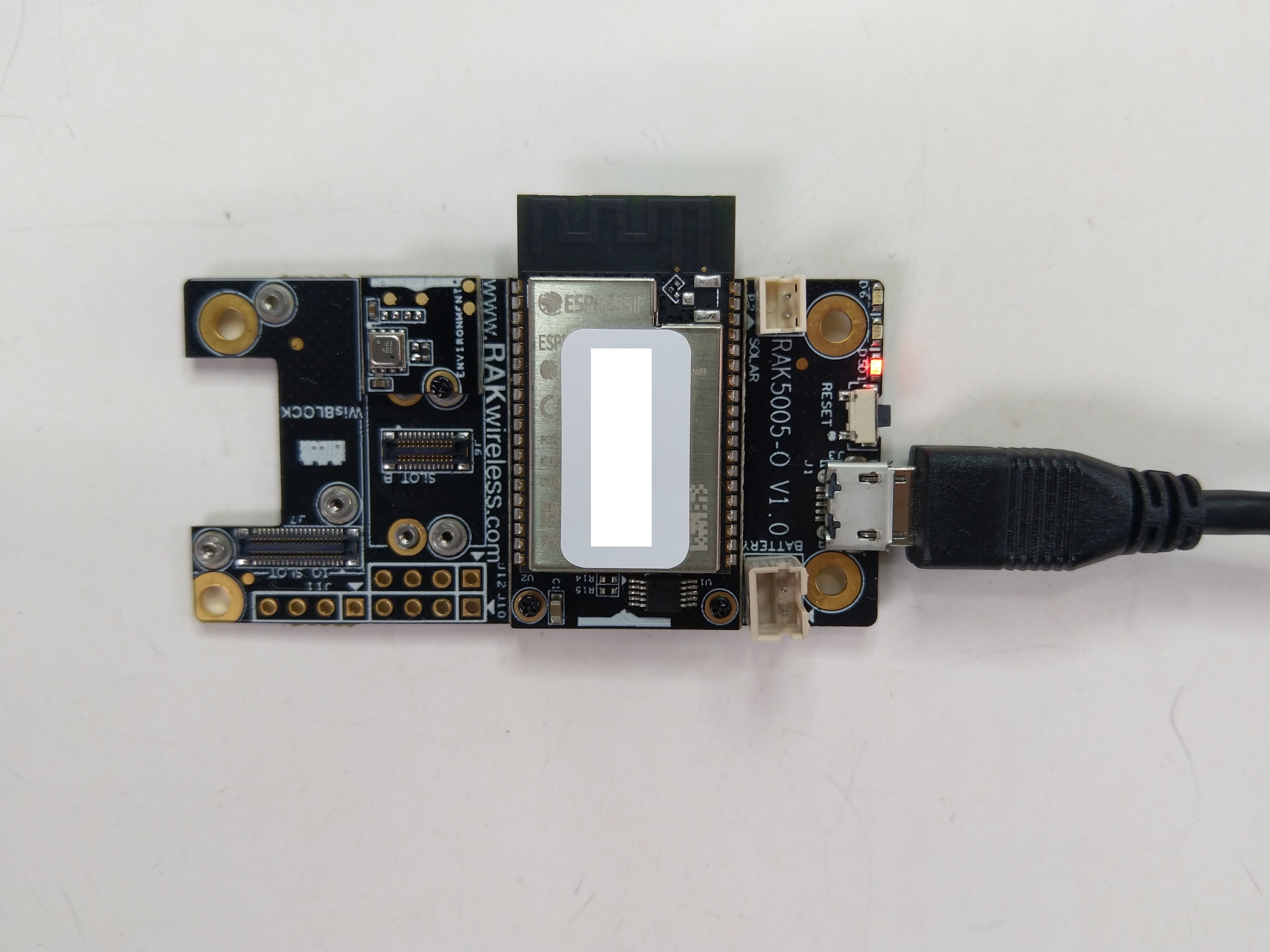
The RAKwireless RAK2305 WisBlock WiFi Interface module is also based on an Expressif ESP32 processor which is supported by the .NET nanoFramework. The RAK2305 WisBlock WiFi Interface module plugs into an IO Slot rather than a Core Slot so I wanted to see if Inter-Integrated Circuit(I2C) bus devices would work with it.
The RAK2305 WisBlock WiFi Interface has one I2C port and TXD0/RXD0 are not connected to the base board’s Universal Serial Bus(USB) port.

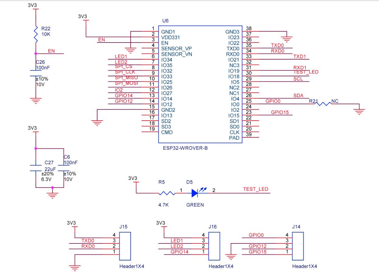
The I2C1 the SDA(serial data) and SCL(serial clock line) have to be mapped to physical pins on the Expressif ESP32 processor using the nanoFramework ESP32 support NuGet. package
                Configuration.SetPinFunction(Gpio.IO04, DeviceFunction.I2C1_DATA);
                Configuration.SetPinFunction(Gpio.IO05, DeviceFunction.I2C1_CLOCK)
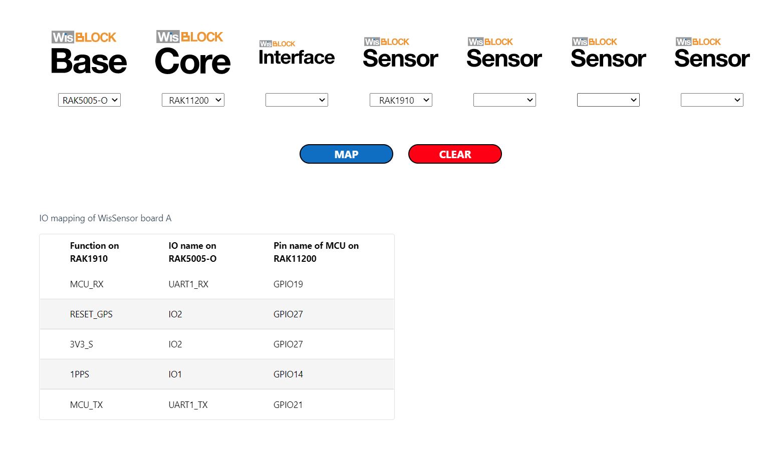
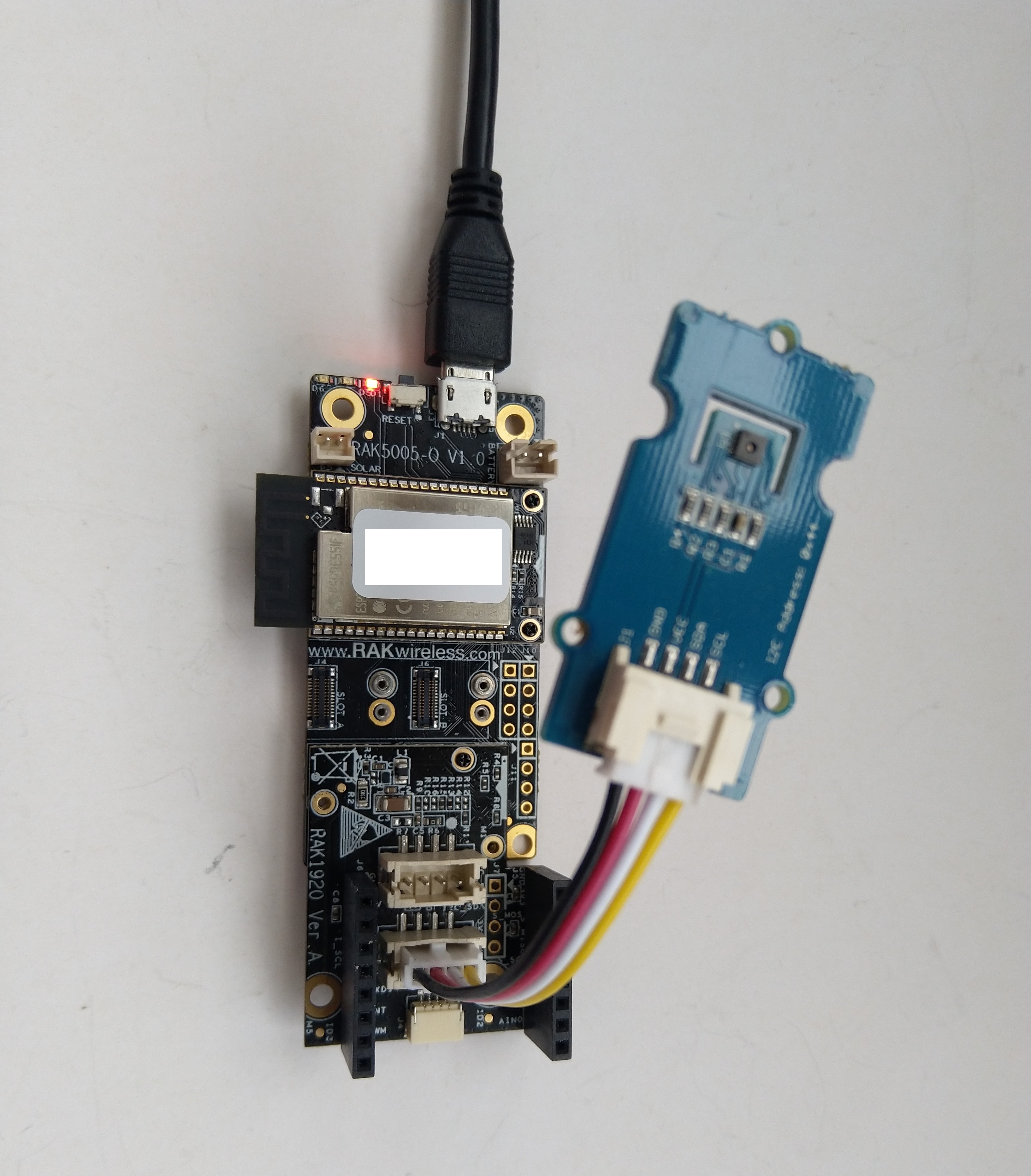
The test project uses a RAK1901 WisBlock Temperature and Humidity Sensor(SHTC3) WisBlock Sensor (which has nanoFramework.IoTDevice library support) plugged into a RAK5005 WisBlock Base Board.
//---------------------------------------------------------------------------------
// Copyright (c) September 2022, devMobile Software
//
// Licensed under the Apache License, Version 2.0 (the "License");
// you may not use this file except in compliance with the License.
// You may obtain a copy of the License at
//
// http://www.apache.org/licenses/LICENSE-2.0
//
// Unless required by applicable law or agreed to in writing, software
// distributed under the License is distributed on an "AS IS" BASIS,
// WITHOUT WARRANTIES OR CONDITIONS OF ANY KIND, either express or implied.
// See the License for the specific language governing permissions and
// limitations under the License.
//
// https://docs.rakwireless.com/Product-Categories/WisBlock/RAK2305
//
// https://docs.rakwireless.com/Product-Categories/WisBlock/RAK11200
//
// https://store.rakwireless.com/products/rak1901-shtc3-temperature-humidity-sensor
//
// https://github.com/nanoframework/nanoFramework.IoT.Device/tree/develop/devices/Shtc3
//
//---------------------------------------------------------------------------------
namespace devMobile.IoT.RAK.Wisblock.RAK1901
{
using System;
using System.Diagnostics;
using System.Device.I2c;
using System.Threading;
using nanoFramework.Hardware.Esp32;
using Iot.Device.Shtc3;
public class Program
{
public static void Main()
{
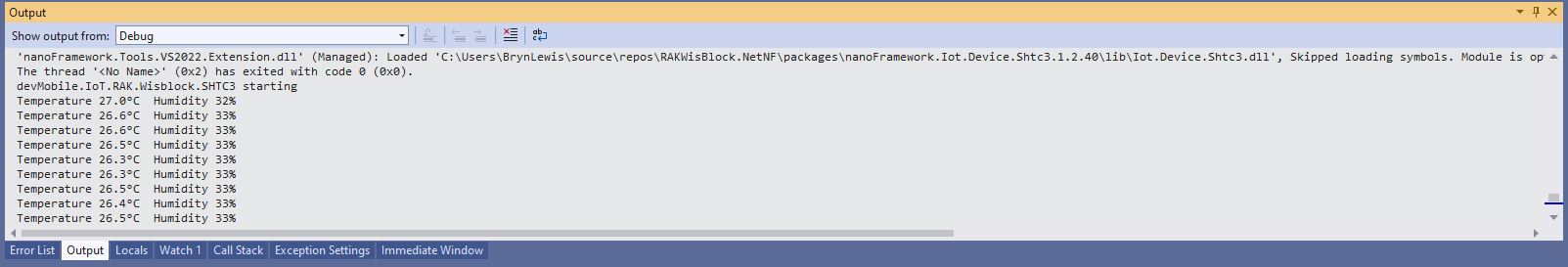
Debug.WriteLine("devMobile.IoT.RAK.Wisblock.RAK11200RAK1901 starting");
try
{
// RAK11200 & RAK2305
Configuration.SetPinFunction(Gpio.IO04, DeviceFunction.I2C1_DATA);
Configuration.SetPinFunction(Gpio.IO05, DeviceFunction.I2C1_CLOCK);
I2cConnectionSettings settings = new(1, Shtc3.DefaultI2cAddress);
using (I2cDevice device = I2cDevice.Create(settings))
using (Shtc3 shtc3 = new(device))
{
while (true)
{
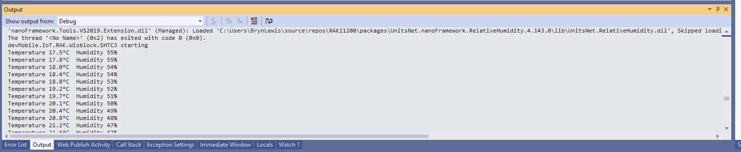
if (shtc3.TryGetTemperatureAndHumidity(out var temperature, out var relativeHumidity))
{
Debug.WriteLine($"Temperature {temperature.DegreesCelsius:F1}°C Humidity {relativeHumidity.Value:F0}%");
}
Thread.Sleep(10000);
}
}
}
catch (Exception ex)
{
Debug.WriteLine($"SHTC3 initialisation or read failed {ex.Message}");
Thread.Sleep(Timeout.Infinite);
}
}
}
}
I tried to get the RAK2305 WisBlock WiFi Interface going on a RAK19001 WisBlock Dual IO Base Board but the RAK1901 WisBlock Temperature and Humidity Sensor wouldn’t work in any of the six WisBlock sensor ports.

The header pins I had to soldered onto RAK2305 WisBlock WiFi Interface had to be trimmed to it would fit on the RAK19001 WisBlock Dual IO Base Board.
One of the RAK19001 WisBlock Dual IO Base Board product features is
“The power supply for the WisBlock modules boards can be controlled by the WisBlock Core modules to minimize power consumption”.
My configuration does not have WisBlock Core module so I think the WisBlock Sensor Module were not powered.