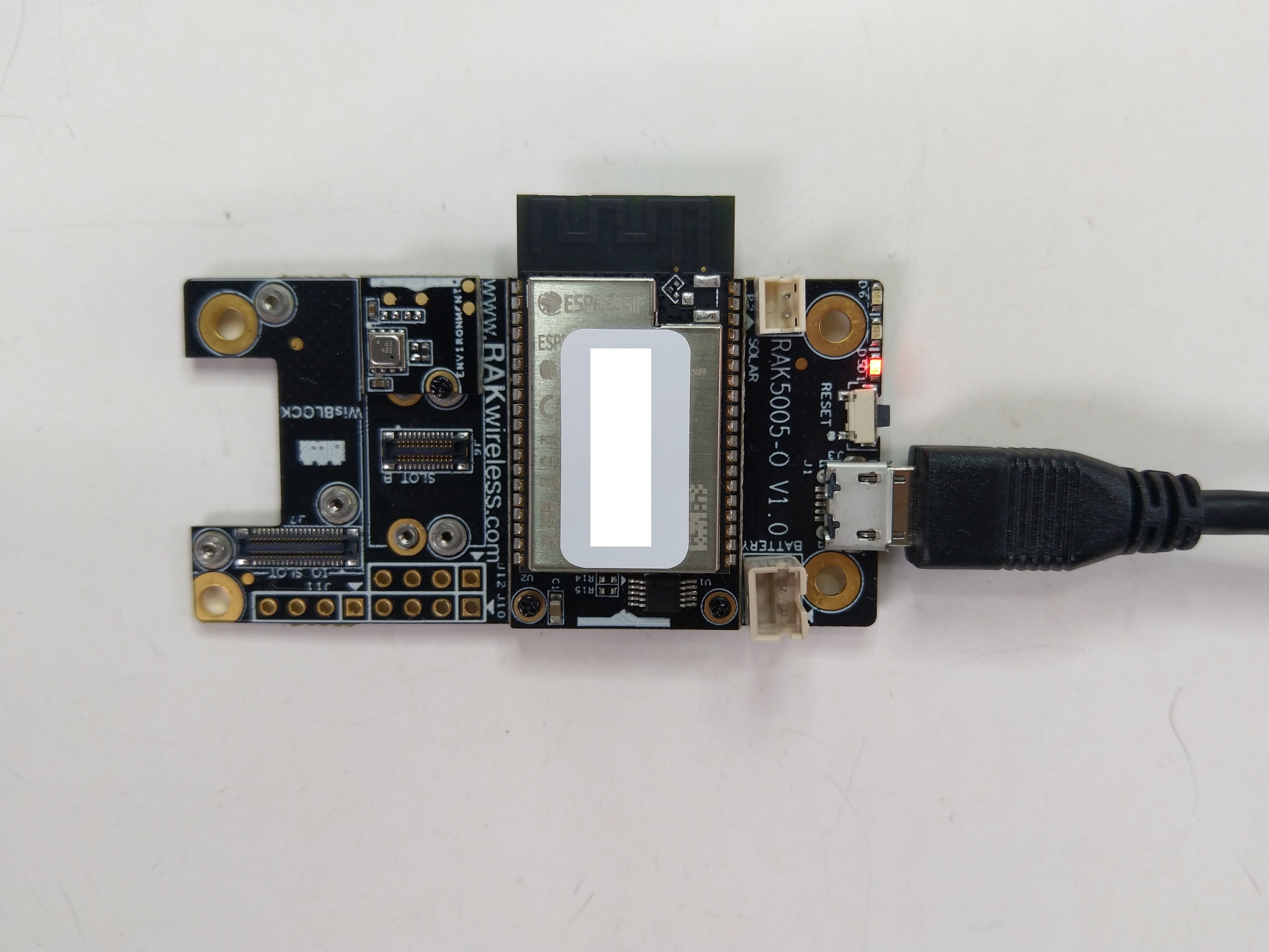
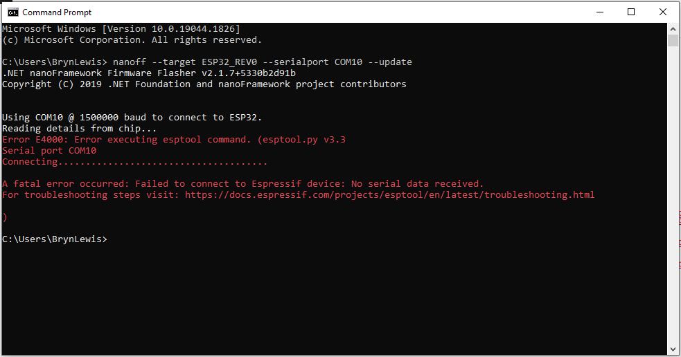
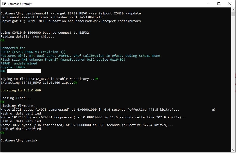
The RAKwireless RAK11200 WisBlock WiFi Module module is based on an Expressif ESP32 processor which is supported by the .NET nanoFramework and I wanted to explore the different ways Inter-Integrated Circuit(I2C) devices could be connected.
The RAK11200 WisBlock WiFi Module has two I2C ports and on the RAK5005 WisBlock Base Board the Wisblock Sensor, and RAK1920 WisBlock Sensor Adapter Module Grove Socket are connected to I2C1.

The I2C1 the SDA(serial data) and SCL(serial clock line) have to be mapped to physical pins on the RAK11200 WisBlock WiFi Module using the nanoFramework ESP32 support NuGet. package
                Configuration.SetPinFunction(Gpio.IO04, DeviceFunction.I2C1_DATA);
                Configuration.SetPinFunction(Gpio.IO05, DeviceFunction.I2C1_CLOCK)
The first sample project uses a RAK1901 SHTC3 WisBlock Sensor because it plugs into the RAK5005 WisBlock Base Board.

public static void Main()
{
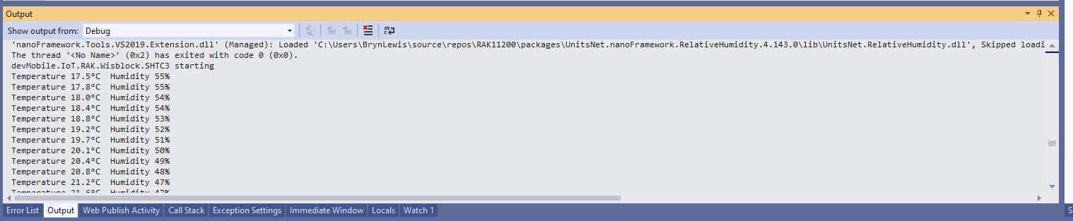
Debug.WriteLine("devMobile.IoT.RAK.Wisblock.SHTC3 starting");
try
{
Configuration.SetPinFunction(Gpio.IO04, DeviceFunction.I2C1_DATA);
Configuration.SetPinFunction(Gpio.IO05, DeviceFunction.I2C1_CLOCK);
I2cConnectionSettings settings = new(1, Shtc3.DefaultI2cAddress);
using (I2cDevice device = I2cDevice.Create(settings))
using (Shtc3 shtc3 = new(device))
{
while (true)
{
if (shtc3.TryGetTemperatureAndHumidity(out var temperature, out var relativeHumidity))
{
Debug.WriteLine($"Temperature {temperature.DegreesCelsius:F1}°C Humidity {relativeHumidity.Value:F0}%");
}
Thread.Sleep(10000);
}
}
}
catch (Exception ex)
{
Debug.WriteLine($"SHTC3 initialisation or read failed {ex.Message}");
Thread.Sleep(Timeout.Infinite);
}
}
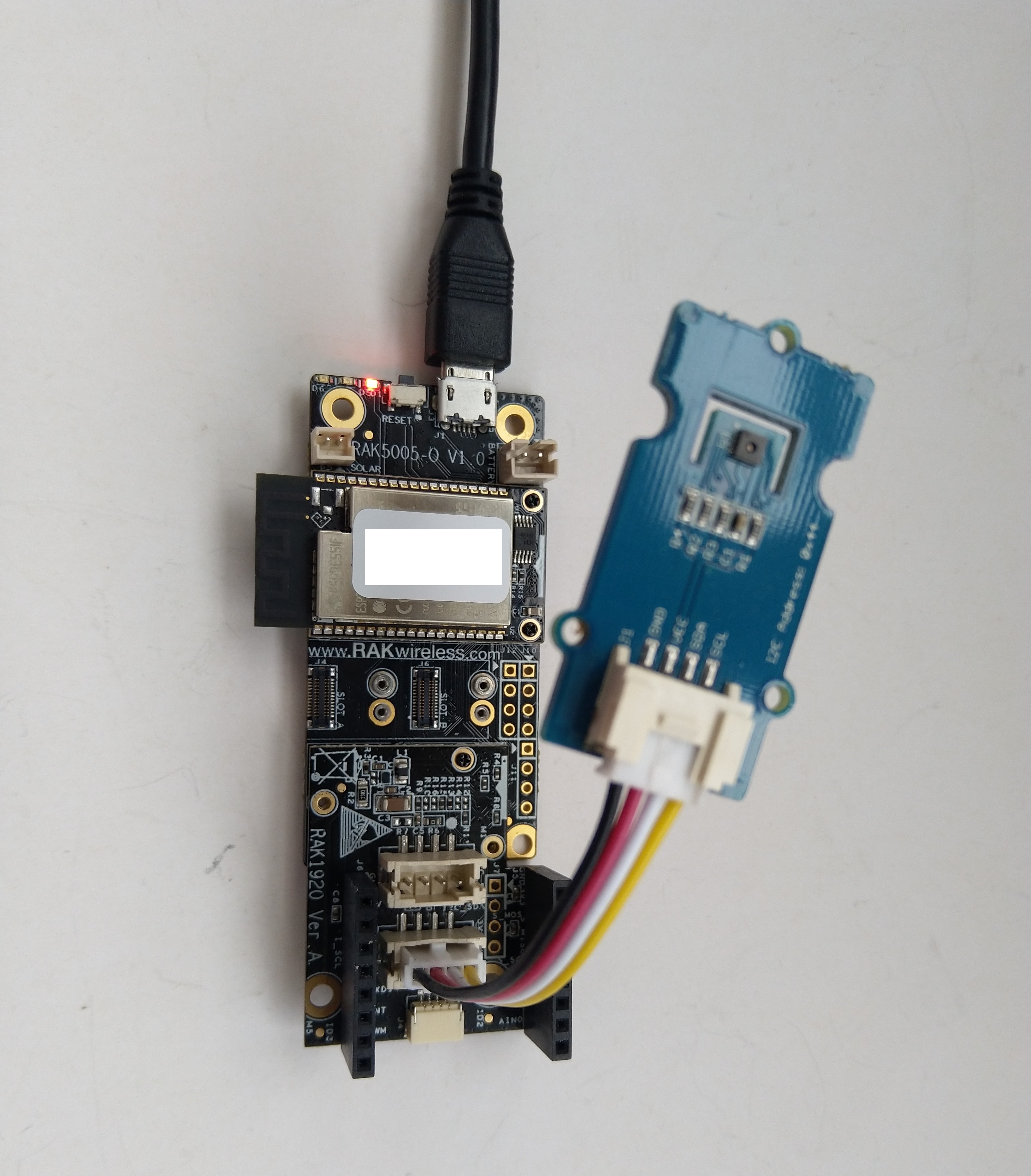
The second sample uses a Seeedstudio Grove – Temperature & Humidity Sensor (SHT31) pluged into a RAK1920 Sensor Adapter for Click, QWIIC and Grove Modules.
public static void Main()
{
    Debug.WriteLine("devMobile.IoT.RAK.Wisblock.SHT31 starting");

    try
    {
        Configuration.SetPinFunction(Gpio.IO04, DeviceFunction.I2C1_DATA);
        Configuration.SetPinFunction(Gpio.IO05, DeviceFunction.I2C1_CLOCK);

        I2cConnectionSettings settings = new(1, (byte)I2cAddress.AddrLow);

        using (I2cDevice device = I2cDevice.Create(settings))
        using (Sht3x sht31 = new(device))
        {

            while (true)
            {
                var temperature = sht31.Temperature;
                var relativeHumidity = sht31.Humidity;

                Debug.WriteLine($"Temperature {temperature.DegreesCelsius:F1}°C  Humidity {relativeHumidity.Value:F0}%");

                Thread.Sleep(10000);
            }
        }
    }
    catch (Exception ex)
    {
        Debug.WriteLine($"SHT31 initialisation or read failed {ex.Message}");

        Thread.Sleep(Timeout.Infinite);
     }
}

The SHTC3 and SHT31 sensors were used because they both have nanoFramework.IoTDevice library support.