Random wanderings through Microsoft Azure esp. PaaS plumbing, the IoT bits, AI on Micro controllers, AI on Edge Devices, .NET nanoFramework, .NET Core on *nix and ML.NET+ONNX
The voltage my test setup was calculating looked wrong, then I realised that the sample calculation in the RAK Wireless forums wasn’t applicable to my setup.
I updated the formula used to calculate the battery voltage and deployed the application
public static void Main()
{
    Debug.WriteLine($"{DateTime.UtcNow:HH:mm:ss} devMobile.IoT.RAK.Wisblock.AzureIoTHub.RAK11200.PowerSleep starting");

    Thread.Sleep(5000);

    try
    {
        double batteryVoltage;

        Configuration.SetPinFunction(Gpio.IO04, DeviceFunction.I2C1_DATA);
        Configuration.SetPinFunction(Gpio.IO05, DeviceFunction.I2C1_CLOCK);

        Debug.WriteLine($"{DateTime.UtcNow:HH:mm:ss} Battery voltage measurement");

        // Configure Analog input (AIN0) port then read the "battery charge"
        AdcController adcController = new AdcController();

        using (AdcChannel batteryVoltageAdcChannel = adcController.OpenChannel(AdcControllerChannel))
        {
            batteryVoltage = batteryVoltageAdcChannel.ReadValue() / 723.7685;

            Debug.WriteLine($" BatteryVoltage {batteryVoltage:F2}");

            if (batteryVoltage < Config.BatteryVoltageBrownOutThreshold)
            {
                Sleep.EnableWakeupByTimer(Config.FailureRetryInterval);
                Sleep.StartDeepSleep();
            }
        }
        catch (Exception ex)
        {
...
}
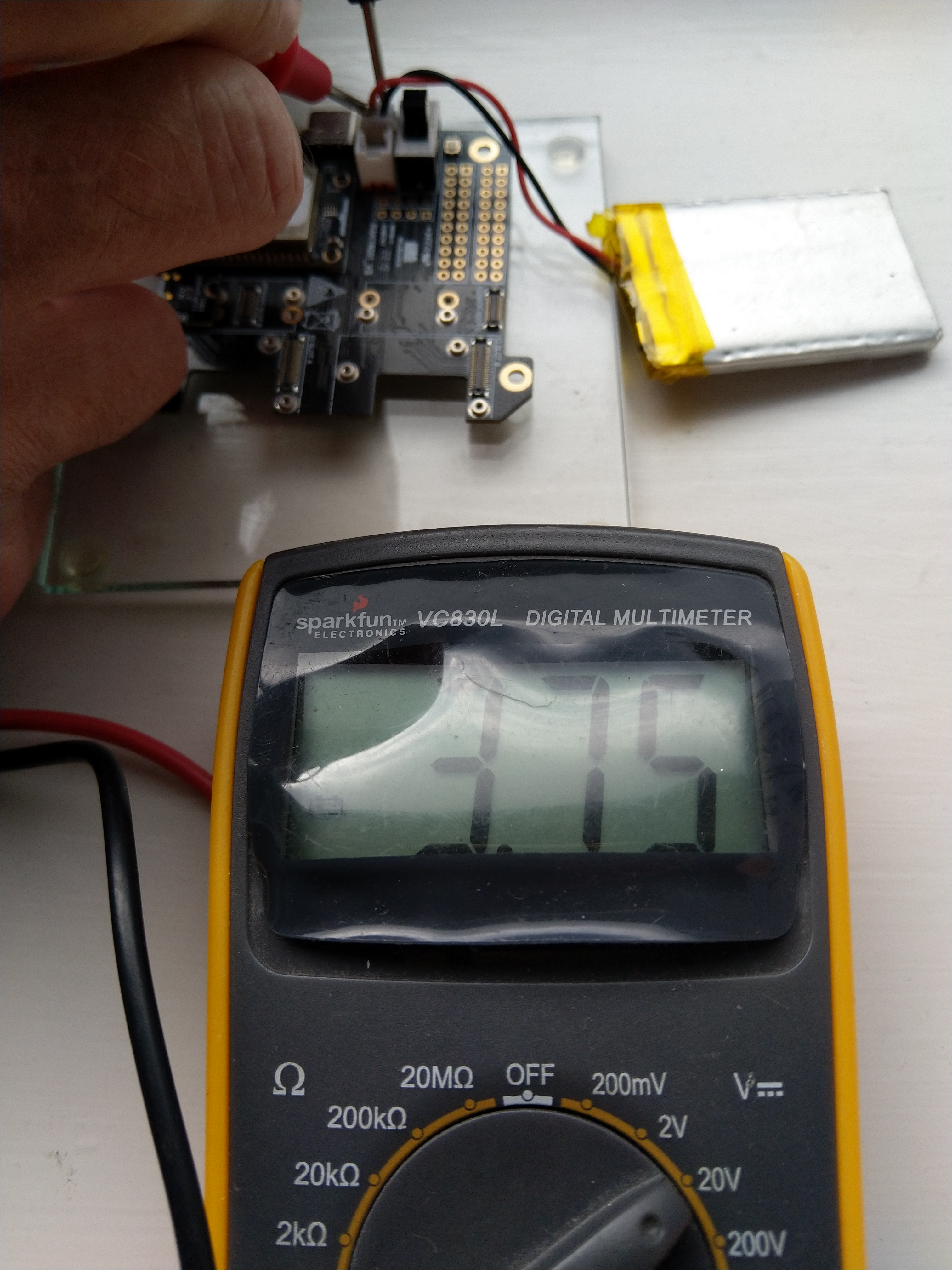
To test the accuracy of the voltage calculation I am going to run my setup on the office windowsill for a week regularly measuring the voltage. Then, turn the solar panel over (so the battery is not getting charged) and monitor the battery discharging until the RAK11200 WisBlock WiFi Module won’t connect to the network.
After some “tinkering” I found the voltage calculation was surprisingly accurate (usually within 0.01V) for my RAK19001 and RAK19007 base boards.
When the battery voltage was close to its minimum working voltage of the ESP32 device it would reboot when the WifiNetworkHelper.ConnectDhcp method was called. This would quickly drain the battery flat even when the solar panel was trying to charge the battery.
Now, before trying to connect to the wireless network the battery voltage is checked and if too low (more experimentation required) the device goes into a deep sleep for a configurable period (more experimentation required). This is so the solar panel can charge the battery to a level where wireless connectivity will work.
public static void Main()
{
    Debug.WriteLine($"{DateTime.UtcNow:HH:mm:ss} devMobile.IoT.RAK.Wisblock.AzureIoTHub.RAK11200.PowerSleep starting");

    Thread.Sleep(5000);

    try
    {
        Configuration.SetPinFunction(Gpio.IO04, DeviceFunction.I2C1_DATA);
        Configuration.SetPinFunction(Gpio.IO05, DeviceFunction.I2C1_CLOCK);

        Debug.WriteLine($"{DateTime.UtcNow:HH:mm:ss} Wifi connecting");

        if (!WifiNetworkHelper.ConnectDhcp(Config.Ssid, Config.Password, requiresDateTime: true))
       {
            if (NetworkHelper.HelperException != null)
            {
                 Debug.WriteLine($"{DateTime.UtcNow:HH:mm:ss} WifiNetworkHelper.ConnectDhcp failed {NetworkHelper.HelperException}");
            }

            Sleep.EnableWakeupByTimer(Config.FailureRetryInterval);
            Sleep.StartDeepSleep();
        }

        Debug.WriteLine($"{DateTime.UtcNow:HH:mm:ss} Wifi connected");

        // Configure the SHTC3
        I2cConnectionSettings settings = new(I2cDeviceBusID, Shtc3.DefaultI2cAddress);
        I2cDevice device = I2cDevice.Create(settings);
        Shtc3 shtc3 = new(device);

        // Assuming that if TryGetTemperatureAndHumidity fails accessing temperature or relativeHumidity will cause an exception
        shtc3.TryGetTemperatureAndHumidity(out var temperature, out var relativeHumidity);

#if SLEEP_SHT3C
        shtc3.Sleep();
#endif

        // Configure Analog input (AIN0) port then read the "battery charge"
        AdcController adcController = new AdcController();
        AdcChannel batteryChargeAdcChannel = adcController.OpenChannel(AdcControllerChannel);

        double batteryCharge = batteryChargeAdcChannel.ReadRatio() * 100.0;

        Debug.WriteLine($" Temperature {temperature.DegreesCelsius:F1}°C Humidity {relativeHumidity.Value:F0}% BatteryCharge {batteryCharge:F1}");

        // Assemble the JSON payload, should use nanoFramework.Json
        string payload = $"{{\"RelativeHumidity\":{relativeHumidity.Value:F0},\"Temperature\":{temperature.DegreesCelsius.ToString("F1")}, \"BatteryCharge\":{batteryCharge:F1}}}";

        // Configure the HttpClient uri, certificate, and authorization
        string uri = $"{Config.AzureIoTHubHostName}.azure-devices.net/devices/{Config.DeviceID}";

        HttpClient httpClient = new HttpClient()
        {
            SslProtocols = System.Net.Security.SslProtocols.Tls12,
            HttpsAuthentCert = new X509Certificate(Config.DigiCertBaltimoreCyberTrustRoot),
            BaseAddress = new Uri($"https://{uri}/messages/events?api-version=2020-03-13"),
        };
        httpClient.DefaultRequestHeaders.Add("Authorization", SasTokenGenerate(uri, Config.Key, DateTime.UtcNow.Add(Config.SasTokenRenewFor)));

        Debug.WriteLine($"{DateTime.UtcNow:HH:mm:ss} Azure IoT Hub device {Config.DeviceID} telemetry update start");

        HttpResponseMessage response = httpClient.Post("", new StringContent(payload));

        Debug.WriteLine($"{DateTime.UtcNow:HH:mm:ss} Response code:{response.StatusCode}");

        response.EnsureSuccessStatusCode();
    }
    catch (Exception ex)
    {
        Debug.WriteLine($"{DateTime.UtcNow:HH:mm:ss} Azure IoT Hub telemetry update failed:{ex.Message} {ex?.InnerException?.Message}");

        Sleep.EnableWakeupByTimer(Config.FailureRetryInterval);
        Sleep.StartDeepSleep();
    }

    Sleep.EnableWakeupByTimer(Config.TelemetryUploadInterval);
#if SLEEP_LIGHT
    Sleep.StartLightSleep();
#endif
#if SLEEP_DEEP
    Sleep.StartDeepSleep();
#endif
 }
The LightSleep or DeepSleep based code is significantly less complex because the allocation and deallocation of resources does not have to be managed because the application is restarted when the WakeUp Timer triggers.
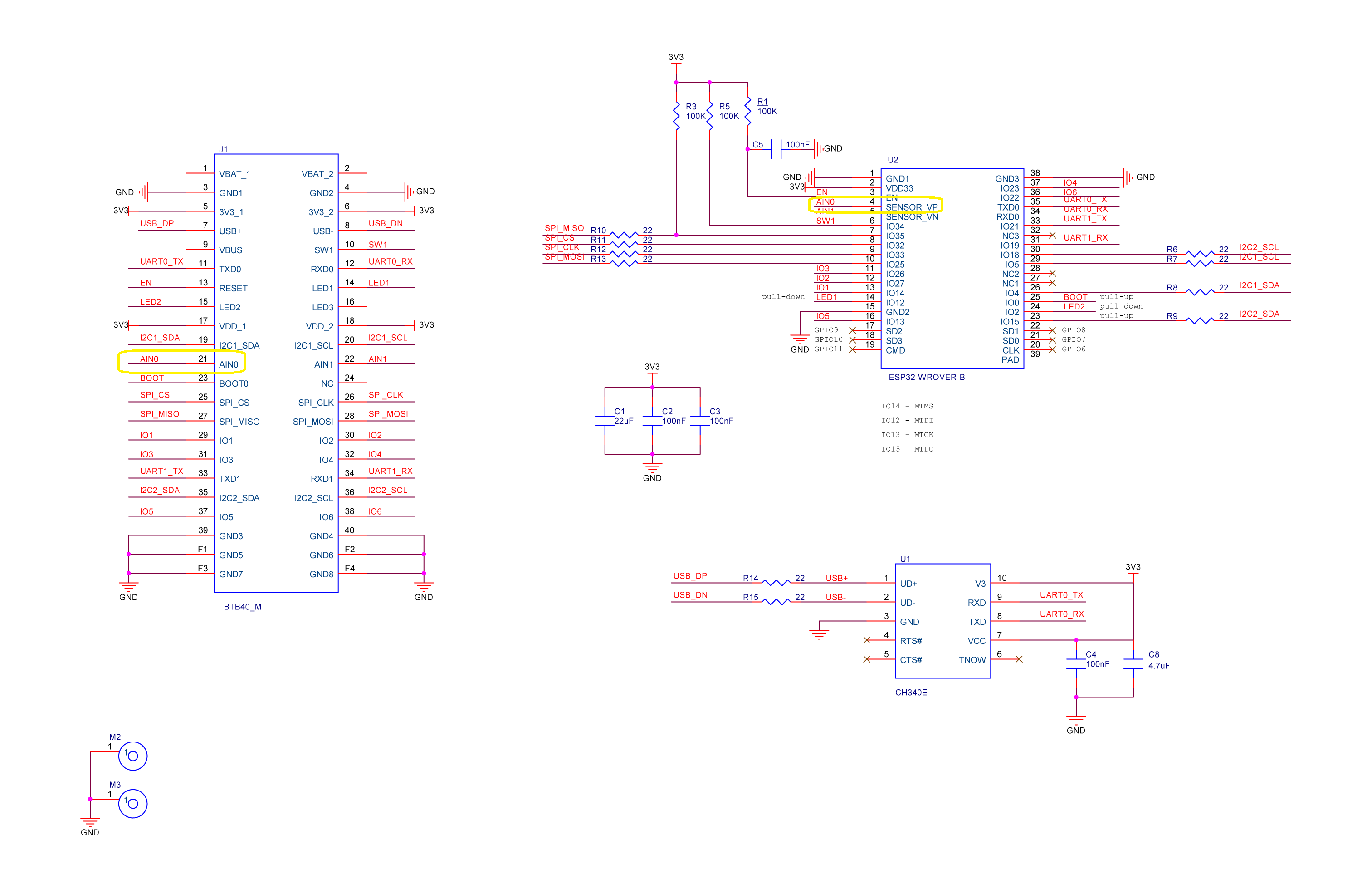
RAK1702 Schematic with voltage divider to ADC_VBAT connection highlighted
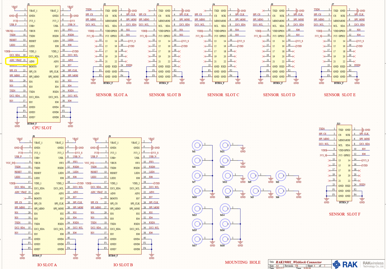
RAK1701 Schematic with ADC_VBAT to CPU slot connection highlighted
The RAK19007 WisBlock Base Board has a voltage divider (R3&R4 with output ADC_VBAT) which is connected (via R7) to pin 21(AIN0) on the CPU slot connector.
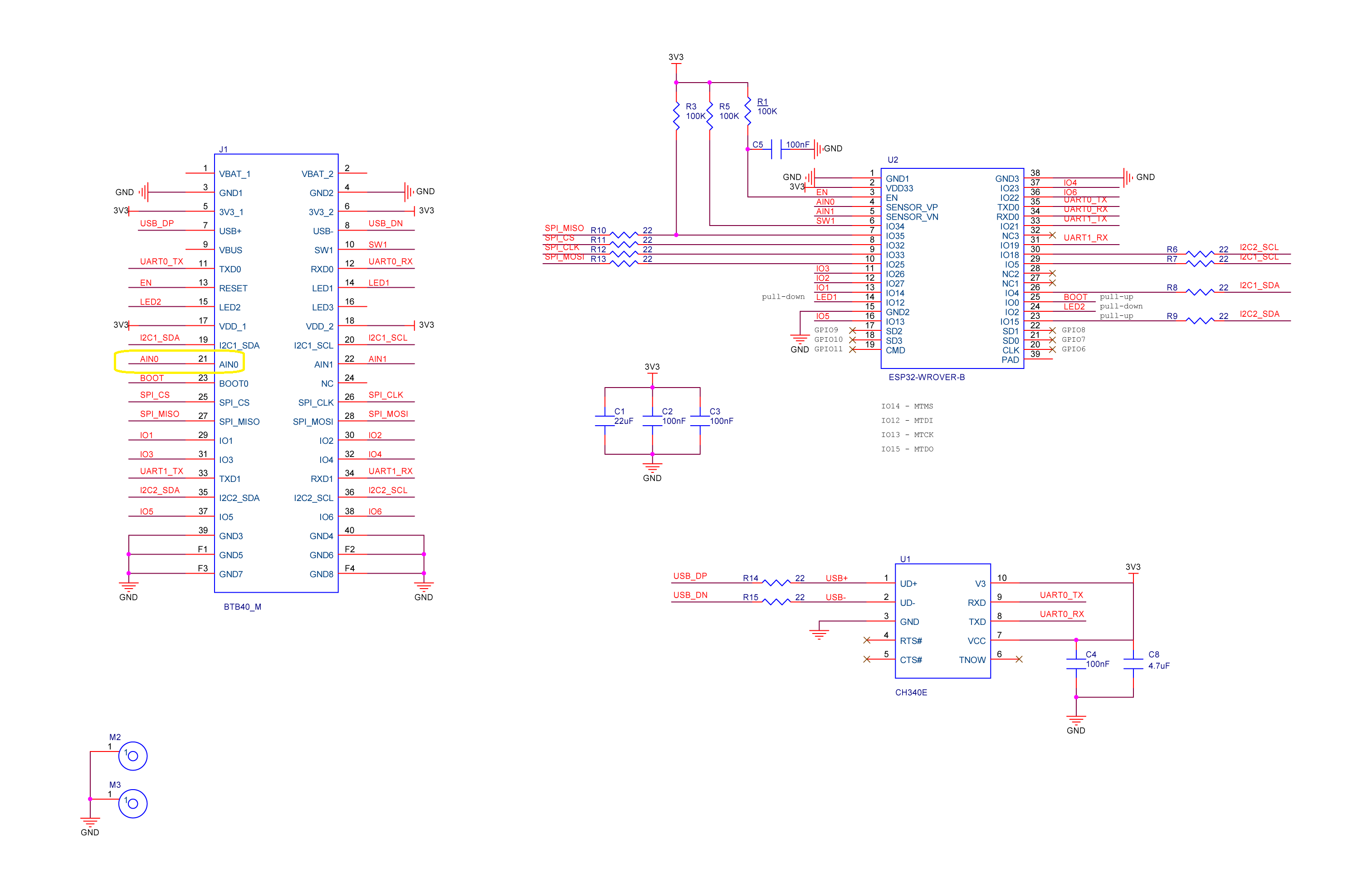
RAK11200 schematic with CPU Slot to ESP32-WROVER-B connection highlighted
 public class Program
 {
     private const int I2cDeviceBusID = 1;
     private const int AdcControllerChannel = 0;

     public static void Main()
     {
         DateTime sasTokenValidUntilUtc = DateTime.UtcNow;

         Debug.WriteLine($"{DateTime.UtcNow:HH:mm:ss} devMobile.IoT.RAK.Wisblock.AzureIoTHub.RAK11200.PowerBaseline starting");

         Configuration.SetPinFunction(Gpio.IO04, DeviceFunction.I2C1_DATA);
         Configuration.SetPinFunction(Gpio.IO05, DeviceFunction.I2C1_CLOCK);

         if (!WifiNetworkHelper.ConnectDhcp(Config.Ssid, Config.Password, requiresDateTime: true))
         {
             if (NetworkHelper.HelperException != null)
             {
                 Debug.WriteLine($"{DateTime.UtcNow:HH:mm:ss} WifiNetworkHelper.ConnectDhcp failed {NetworkHelper.HelperException}");
             }

             Thread.Sleep(Timeout.Infinite);
         }

         string uri = $"{Config.AzureIoTHubHostName}.azure-devices.net/devices/{Config.DeviceID}";

         // not setting Authorization here as it will change as SAS Token refreshed
         HttpClient httpClient = new HttpClient
         {
             SslProtocols = System.Net.Security.SslProtocols.Tls12,
             HttpsAuthentCert = new X509Certificate(Config.DigiCertBaltimoreCyberTrustRoot),
             BaseAddress = new Uri($"https://{uri}/messages/events?api-version=2020-03-13"),
         };

         I2cConnectionSettings settings = new(I2cDeviceBusID, Shtc3.DefaultI2cAddress);
         I2cDevice device = I2cDevice.Create(settings);
         Shtc3 shtc3 = new(device);

         AdcController adcController = new AdcController();
         AdcChannel batteryChargeAdcChannel = adcController.OpenChannel(AdcControllerChannel);

         string sasToken = "";

         while (true)
         {
             DateTime standardisedUtcNow = DateTime.UtcNow;

             Debug.WriteLine($"{DateTime.UtcNow:HH:mm:ss} Azure IoT Hub device {Config.DeviceID} telemetry update start");

             if (sasTokenValidUntilUtc <= standardisedUtcNow)
             {
                 sasTokenValidUntilUtc = standardisedUtcNow.Add(Config.SasTokenRenewEvery);

                 sasToken = SasTokenGenerate(uri, Config.Key, sasTokenValidUntilUtc);

                 Debug.WriteLine($" Renewing SAS token for {Config.SasTokenRenewFor} valid until {sasTokenValidUntilUtc:HH:mm:ss dd-MM-yy}");
             }

             if (!shtc3.TryGetTemperatureAndHumidity(out var temperature, out var relativeHumidity))
             {
                 Debug.WriteLine($" Temperature and Humidity read failed");

                 continue;
             }

             double batteryCharge = batteryChargeAdcChannel.ReadRatio() * 100.0;

             Debug.WriteLine($" Temperature {temperature.DegreesCelsius:F1}°C Humidity {relativeHumidity.Value:F0}% BatteryCharge {batteryCharge:F1}%");

             string payload = $"{{\"RelativeHumidity\":{relativeHumidity.Value:F0},\"Temperature\":{temperature.DegreesCelsius.ToString("F1")}, \"BatteryCharge\":{batteryCharge:F1}}}";

             try
             {
                 using (HttpContent content = new StringContent(payload))
                 {
                     content.Headers.Add("Authorization", sasToken);

                     using (HttpResponseMessage response = httpClient.Post("", content))
                     {
                         Console.WriteLine($"{DateTime.UtcNow:HH:mm:ss} Response code:{response.StatusCode}");

                         response.EnsureSuccessStatusCode();
                     }
                 }
             }
             catch (Exception ex)
             {
                 Debug.WriteLine($"{DateTime.UtcNow:HH:mm:ss} Azure IoT Hub POST failed:{ex.Message} {ex?.InnerException?.Message}");
             }

             Debug.WriteLine($"{DateTime.UtcNow:HH:mm:ss} Azure IoT Hub telemetry update done");

             Thread.Sleep(Config.TelemetryUploadInterval);
         }
     }
...
}
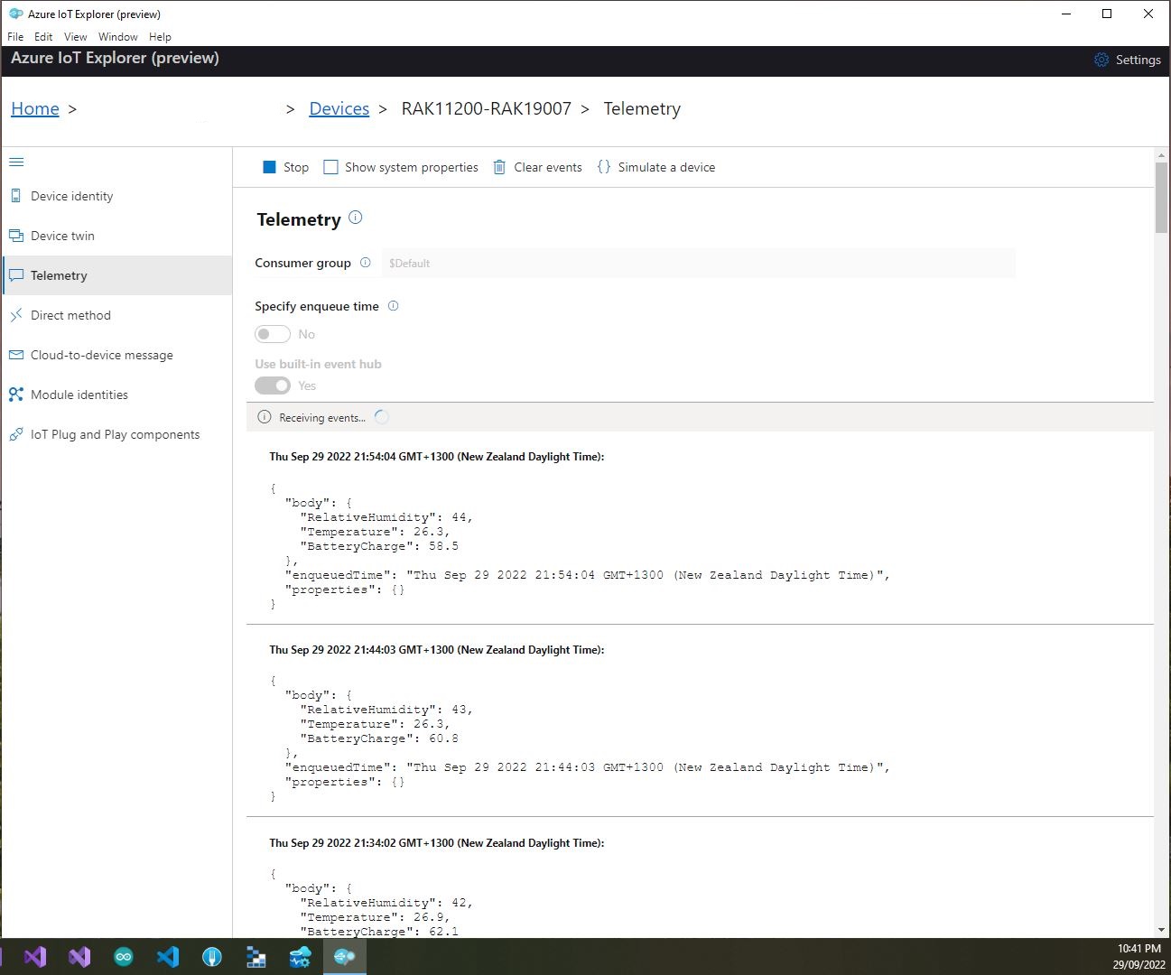
I used Azure IoT Explorer to monitor the Azure IoT Hub device telemetry to see how BatteryCharge value decreased to a level where the device wouldn’t transmit.
Azure IoT Explorer telemetry – device connected to a USB charger (11:01:19) then un-plugged (11:02:02)
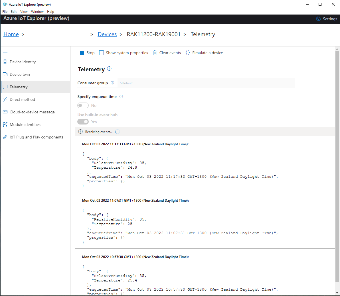
Azure IoT Explorer telemetry – Last two messages sent by the device
With no use of the “power conservation” functionality of the ESP32-WROVER-B powered by a 1200mAH battery the device ran for approximately 11hrs (11:00am – 10:00pm).
RAK2305 Wisblock AIN0 pin highlighted
I think the RAK2305 will not be able to measure “battery charge” as the SENSOR_VP pin on the Espressif ESP32-WROVER-B is not connected to AIN0.
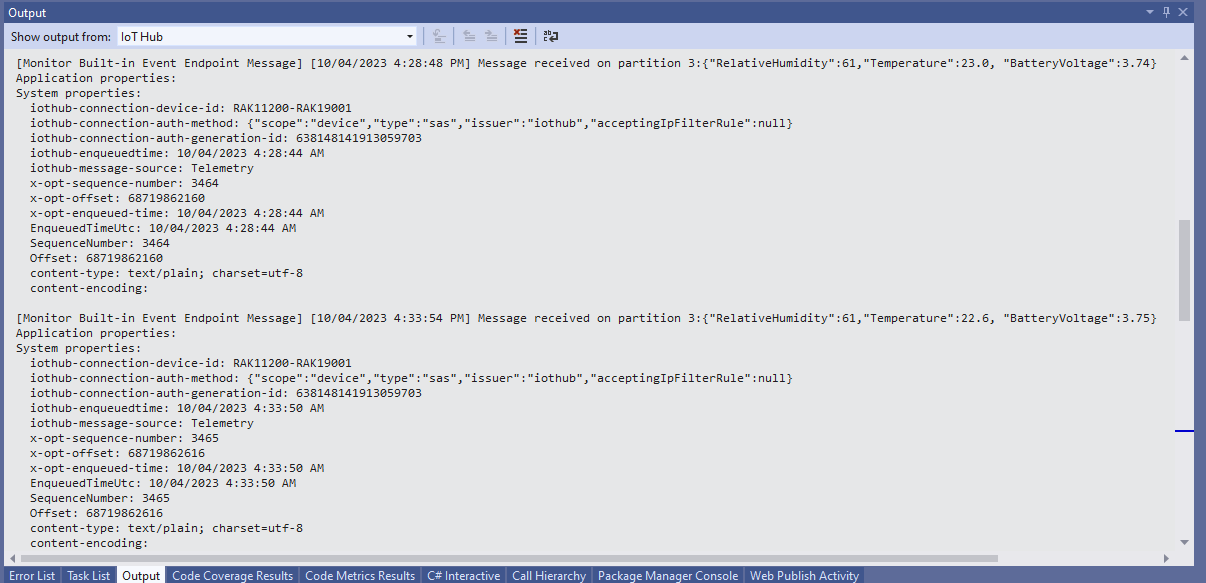
I was using Azure IoT Explorer to monitor the telemetry and found that the initial versions of the application would fail after 6 or 7 hours. After reviewing the code I added a couple of “using” statements which appear to have fixed the problem as the soak test has been running for 12hrs, 24hrs, 36hrs, 48hrs, 96hrs…
//---------------------------------------------------------------------------------
// Copyright (c) August 2022, devMobile Software
//
// Licensed under the Apache License, Version 2.0 (the "License");
// you may not use this file except in compliance with the License.
// You may obtain a copy of the License at
//
// http://www.apache.org/licenses/LICENSE-2.0
//
// Unless required by applicable law or agreed to in writing, software
// distributed under the License is distributed on an "AS IS" BASIS,
// WITHOUT WARRANTIES OR CONDITIONS OF ANY KIND, either express or implied.
// See the License for the specific language governing permissions and
// limitations under the License.
//
// RAK Core WisBlock
// https://docs.rakwireless.com/Product-Categories/WisBlock/RAK11200
//
// RAK WisBlock Wireless
// https://docs.rakwireless.com/Product-Categories/WisBlock/RAK2305/Overview/
//
// RAK WisBlock Bases
// https://docs.rakwireless.com/Product-Categories/WisBlock/RAK5005-O
// https://docs.rakwireless.com/Product-Categories/WisBlock/RAK19001
//
// RAK WisBlock Sensor
// https://docs.rakwireless.com/Product-Categories/WisBlock/RAK1910
//
// Uses the library
// https://github.com/mboud/TinyGPSPlusNF
//
// Inspired by
// https://github.com/RAKWireless/WisBlock/tree/master/examples/common/sensors/RAK1910_GPS_UBLOX7
//
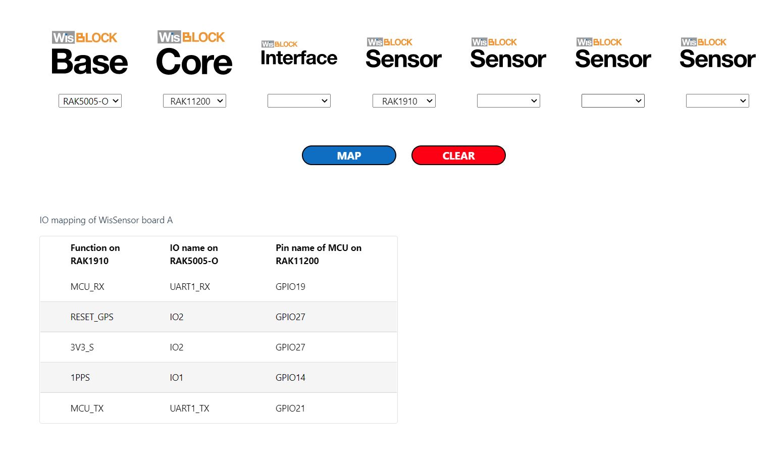
// Pins mapped with
// https://docs.rakwireless.com/Knowledge-Hub/Pin-Mapper/
//
// Flash device with
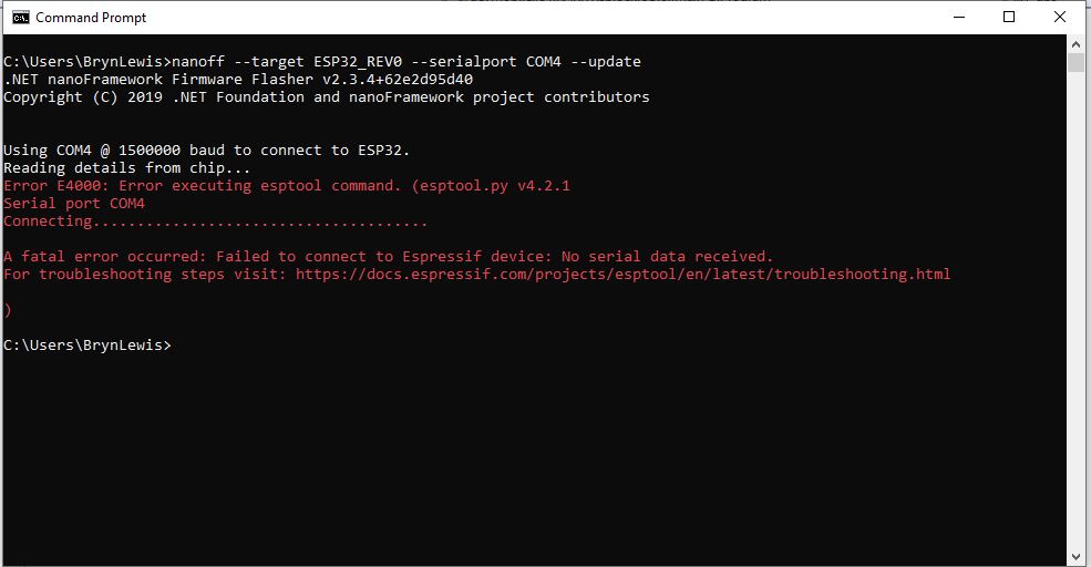
// nanoff --target ESP32_REV0 --serialport COM16 --update
//
//---------------------------------------------------------------------------------
namespace devMobile.IoT.RAK.Wisblock.RAK1910
{
using System;
using System.Device.Gpio;
using System.Diagnostics;
using System.IO.Ports;
using System.Threading;
using nanoFramework.Hardware.Esp32;
using TinyGPSPlusNF;
public class Program
{
private static TinyGPSPlus _gps;
public static void Main()
{
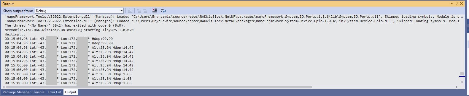
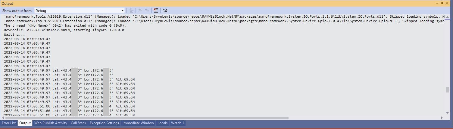
Debug.WriteLine($"devMobile.IoT.RAK.Wisblock.RAK1910 starting TinyGPS {TinyGPSPlus.LibraryVersion}");
try
{
#if RAK11200
Configuration.SetPinFunction(Gpio.IO21, DeviceFunction.COM2_TX);
Configuration.SetPinFunction(Gpio.IO19, DeviceFunction.COM2_RX);
#endif
#if RAK2350
Configuration.SetPinFunction(Gpio.IO21, DeviceFunction.COM2_RX);
Configuration.SetPinFunction(Gpio.IO19, DeviceFunction.COM2_TX);
#endif
_gps = new TinyGPSPlus();
// UART1 with default Max7Q baudrate
SerialPort serialPort = new SerialPort("COM2", 9600);
serialPort.DataReceived += SerialDevice_DataReceived;
serialPort.Open();
serialPort.WatchChar = '\n';
// Enable the GPS module GPS 3V3_S/RESET_GPS - IO2 - GPIO27
GpioController gpioController = new GpioController();
GpioPin Gps3V3 = gpioController.OpenPin(Gpio.IO27, PinMode.Output);
Gps3V3.Write(PinValue.High);
Debug.WriteLine("Waiting...");
Thread.Sleep(Timeout.Infinite);
}
catch (Exception ex)
{
Debug.WriteLine($"UBlox MAX7Q initialisation failed {ex.Message}");
Thread.Sleep(Timeout.Infinite);
}
}
private static void SerialDevice_DataReceived(object sender, SerialDataReceivedEventArgs e)
{
// we only care if got EoL character
if (e.EventType != SerialData.WatchChar)
{
return;
}
SerialPort serialDevice = (SerialPort)sender;
string sentence = serialDevice.ReadExisting();
if (_gps.Encode(sentence))
{
if (_gps.Date.IsValid)
{
Debug.Write($"{_gps.Date.Year}-{_gps.Date.Month:D2}-{_gps.Date.Day:D2} ");
}
if (_gps.Time.IsValid)
{
Debug.Write($"{_gps.Time.Hour:D2}:{_gps.Time.Minute:D2}:{_gps.Time.Second:D2}.{_gps.Time.Centisecond:D2} ");
}
if (_gps.Location.IsValid)
{
Debug.Write($"Lat:{_gps.Location.Latitude.Degrees:F5}° Lon:{_gps.Location.Longitude.Degrees:F5}° ");
}
if (_gps.Altitude.IsValid)
{
Debug.Write($"Alt:{_gps.Altitude.Meters:F1}M ");
}
if (_gps.Location.IsValid)
{
Debug.Write($"Hdop:{_gps.Hdop.Value:F2}");
}
if (_gps.Date.IsValid || _gps.Time.IsValid || _gps.Location.IsValid || _gps.Altitude.IsValid)
{
Debug.WriteLine("");
}
}
}
}
}
After some experimentation I found that serial port TX/RX lines had to be reversed because both devices would normally be connected to a WisBlock core module.
//---------------------------------------------------------------------------------
// Copyright (c) September 2022, devMobile Software
//
// Licensed under the Apache License, Version 2.0 (the "License");
// you may not use this file except in compliance with the License.
// You may obtain a copy of the License at
//
// http://www.apache.org/licenses/LICENSE-2.0
//
// Unless required by applicable law or agreed to in writing, software
// distributed under the License is distributed on an "AS IS" BASIS,
// WITHOUT WARRANTIES OR CONDITIONS OF ANY KIND, either express or implied.
// See the License for the specific language governing permissions and
// limitations under the License.
//
// https://docs.rakwireless.com/Product-Categories/WisBlock/RAK2305
//
// https://docs.rakwireless.com/Product-Categories/WisBlock/RAK11200
//
// https://store.rakwireless.com/products/rak1901-shtc3-temperature-humidity-sensor
//
// https://github.com/nanoframework/nanoFramework.IoT.Device/tree/develop/devices/Shtc3
//
//---------------------------------------------------------------------------------
namespace devMobile.IoT.RAK.Wisblock.RAK1901
{
using System;
using System.Diagnostics;
using System.Device.I2c;
using System.Threading;
using nanoFramework.Hardware.Esp32;
using Iot.Device.Shtc3;
public class Program
{
public static void Main()
{
Debug.WriteLine("devMobile.IoT.RAK.Wisblock.RAK11200RAK1901 starting");
try
{
// RAK11200 & RAK2305
                Configuration.SetPinFunction(Gpio.IO04, DeviceFunction.I2C1_DATA);
Configuration.SetPinFunction(Gpio.IO05, DeviceFunction.I2C1_CLOCK);
I2cConnectionSettings settings = new(1, Shtc3.DefaultI2cAddress);
using (I2cDevice device = I2cDevice.Create(settings))
using (Shtc3 shtc3 = new(device))
{
while (true)
{
if (shtc3.TryGetTemperatureAndHumidity(out var temperature, out var relativeHumidity))
{
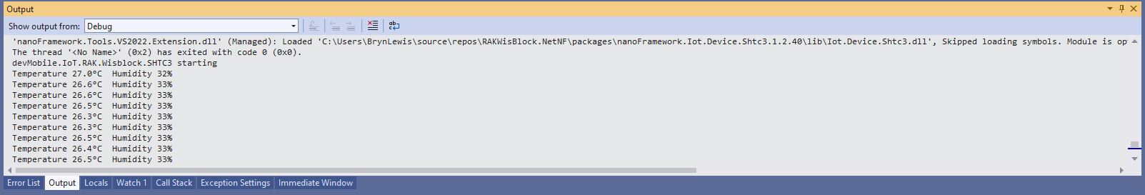
Debug.WriteLine($"Temperature {temperature.DegreesCelsius:F1}°C Humidity {relativeHumidity.Value:F0}%");
}
Thread.Sleep(10000);
}
}
}
catch (Exception ex)
{
Debug.WriteLine($"SHTC3 initialisation or read failed {ex.Message}");
Thread.Sleep(Timeout.Infinite);
}
}
}
}
Visual Studio Output window displaying SHT31 temperature & humidity values
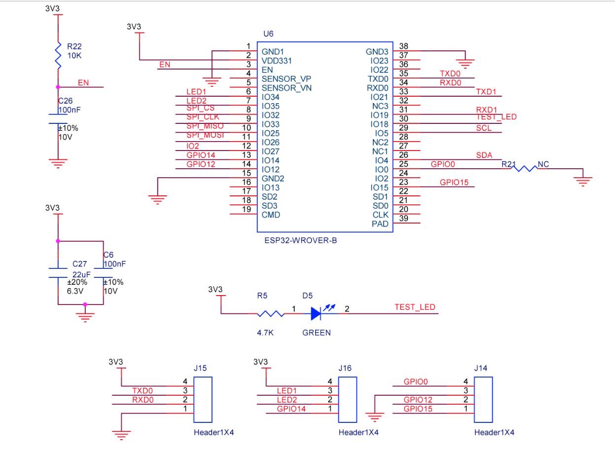
The RAK2305 Low Level Developer documentation described how to upload software developed with the Arduino tools by putting the ESP32 into “bootloader mode”. This is done by connecting (with the white jumper) the GPIO0 and GND pins on J14, and pressing the reset button.
The RAK2305 has has one onboard LED(TEST_LED) attached to IO18 which I added to the .NET nanoFrameworkBlinky sample.
//
// Copyright (c) .NET Foundation and Contributors
// See LICENSE file in the project root for full license information.
//
//
using System;
using System.Device.Gpio;
using System.Threading;
using nanoFramework.Hardware.Esp32;

namespace Blinky
{
   public class Program
   {
      private static GpioController s_GpioController;

      public static void Main()
      {
         s_GpioController = new GpioController();

         // pick a board, uncomment one line for GpioPin; default is STM32F769I_DISCO

         // DISCOVERY4: PD15 is LED6
         //GpioPin led = s_GpioController.OpenPin(PinNumber('D', 15), PinMode.Output);

         // ESP32 DevKit: 4 is a valid GPIO pin in, some boards like Xiuxin ESP32 may require GPIO Pin 2 instead.
         //GpioPin led = s_GpioController.OpenPin(4, PinMode.Output);

         // FEATHER S2:
         //GpioPin led = s_GpioController.OpenPin(13, PinMode.Output);

         // F429I_DISCO: PG14 is LEDLD4
         //GpioPin led = s_GpioController.OpenPin(PinNumber('G', 14), PinMode.Output);

         // NETDUINO 3 Wifi: A10 is LED onboard blue
         //GpioPin led = s_GpioController.OpenPin(PinNumber('A', 10), PinMode.Output);

         // QUAIL: PE15 is LED1
         //GpioPin led = s_GpioController.OpenPin(PinNumber('E', 15), PinMode.Output);

         // STM32F091RC: PA5 is LED_GREEN
         //GpioPin led = s_GpioController.OpenPin(PinNumber('A', 5), PinMode.Output);

         // STM32F746_NUCLEO: PB75 is LED2
         //GpioPin led = s_GpioController.OpenPin(PinNumber('B', 7), PinMode.Output);

         //STM32F769I_DISCO: PJ5 is LD2
         //GpioPin led = s_GpioController.OpenPin(PinNumber('J', 5), PinMode.Output);

         // ST_B_L475E_IOT01A: PB14 is LD2
         //GpioPin led = s_GpioController.OpenPin(PinNumber('B', 14), PinMode.Output);

         // STM32L072Z_LRWAN1: PA5 is LD2
         //GpioPin led = s_GpioController.OpenPin(PinNumber('A', 5), PinMode.Output);

         // TI CC13x2 Launchpad: DIO_07 it's the green LED
         //GpioPin led = s_GpioController.OpenPin(7, PinMode.Output);

         // TI CC13x2 Launchpad: DIO_06 it's the red LED
         //GpioPin led = s_GpioController.OpenPin(6, PinMode.Output);

         // ULX3S FPGA board: for the red D22 LED from the ESP32-WROOM32, GPIO5
         //GpioPin led = s_GpioController.OpenPin(5, PinMode.Output);

         // Silabs SLSTK3701A: LED1 PH14 is LLED1
         //GpioPin led = s_GpioController.OpenPin(PinNumber('H', 14), PinMode.Output);

         // RAK11200 on RAK5005
         //GpioPin led = s_GpioController.OpenPin(Gpio.IO12, PinMode.Output); // LED1 Green
         //GpioPin led = s_GpioController.OpenPin(Gpio.IO02, PinMode.Output); // LED2 Blue

         // RAK11200 on RAK19001 needs battery connected or power switch in rechargeable position.
         //GpioPin led = s_GpioController.OpenPin(Gpio.IO12, PinMode.Output); // LED1 Green
         //GpioPin led = s_GpioController.OpenPin(Gpio.IO02, PinMode.Output); // LED2 Blue

         // RAK2305
         //GpioPin led = s_GpioController.OpenPin(Gpio.IO18, PinMode.Output); // LED Green (Test LED) on device

         // RAK2305 On 5005 throws exceptions
         //GpioPin led = s_GpioController.OpenPin(Gpio.IO34, PinMode.Output); // LED1 Green
         //GpioPin led = s_GpioController.OpenPin(Gpio.IO35, PinMode.Output); // LED2 Blue

         // RAK2305 On 17001 throws exceptions
         //GpioPin led = s_GpioController.OpenPin(Gpio.IO34, PinMode.Output); // LED1 Green
         //GpioPin led = s_GpioController.OpenPin(Gpio.IO35, PinMode.Output); // LED2 Blue

         led.Write(PinValue.Low);

         while (true)
         {
            led.Toggle();
            Thread.Sleep(125);
            led.Toggle();
            Thread.Sleep(125);
            led.Toggle();
            Thread.Sleep(125);
            led.Toggle();
            Thread.Sleep(525);
         }
      }

      static int PinNumber(char port, byte pin)
      {
         if (port < 'A' || port > 'J')
            throw new ArgumentException();

         return ((port - 'A') * 16) + pin;
      }
   }
}
I added the RAK2305 configuration to my version of the nanoFramework Blinky sample and could reliably flash the onboard LED.