Wireless-Tag WT32-SC01 nanoFramework Chuck Norris API Client

Back in 2013 built a demo application which called the Chuck Norris API(ICNAPI) to demonstrate .NET Micro Framework Hypertext Transfer Protocol(HTTP) connectivity and this a new version for the .NET nanoFramework.

Chuck Norris API Home page

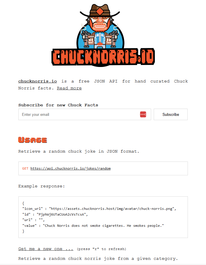
The application uses a System.Net.Http httpClient to call the ICNAPI and nanoFramework.Json to deserialize the responses.

namespace devMobile.IoT.WT32SC01.ChuckNorrisAPI
{
...
    internal class Joke
    {
        public string id { get; set; }
        public string url { get; set; }
        public string value { get; set; }
    }

    public class Program
    {
        public static void Main()
        {
            HttpClient httpClient;

            Debug.WriteLine($"{DateTime.UtcNow:HH:mm:ss} Wifi connecting");

            if (!WifiNetworkHelper.ConnectDhcp(Config.Ssid, Config.Password, requiresDateTime: true))
            {
                if (NetworkHelper.HelperException != null)
                {
                    Debug.WriteLine($"{DateTime.UtcNow:HH:mm:ss} WifiNetworkHelper.ConnectDhcp failed {NetworkHelper.HelperException}");
                }

                Thread.Sleep(Timeout.Infinite);
            }

            Debug.WriteLine($"{DateTime.UtcNow:HH:mm:ss} Wifi connected");

            using (httpClient = new HttpClient())
            {
                httpClient.SslProtocols = System.Net.Security.SslProtocols.Tls12;
                httpClient.HttpsAuthentCert = new X509Certificate(Config.LetsEncryptCACertificate);
                httpClient.BaseAddress = new Uri(Config.ChuckNorrisAPIUrl);

                while (true)
                {
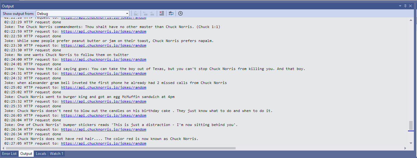
                    Debug.WriteLine($"{DateTime.UtcNow:HH:mm:ss} HTTP request to: {httpClient.BaseAddress.AbsoluteUri}");

                    var response = httpClient.GetString("");

                    Debug.WriteLine($"{DateTime.UtcNow:HH:mm:ss} HTTP request done");

                    Joke joke = (Joke)JsonConvert.DeserializeObject(response, typeof(Joke));

                    Debug.WriteLine($"Joke: {joke.value} ");

                    Thread.Sleep(Config.RequestDelay);
                }
            }
        }
    }
}
Visual Studio 2022 Debug output displaying Chuck Norris facts

The application configuration is stored in a separate file(config.cs) to reduce the likelihood of me accidently checking it into source control.

namespace devMobile.IoT.WT32SC01.ChuckNorrisAPI
{
    internal class Config
    {
        public const string Ssid = "";
        public const string Password = "";
        public const string ChuckNorrisAPIUrl = "https://api.chucknorris.io/jokes/random";

        public const string LetsEncryptCACertificate =
                 @"-----BEGIN CERTIFICATE-----
MIICGzCCAaGgAwIBAgIQQdKd0XLq7qeAwSxs6S+HUjAKBggqhkjOPQQDAzBPMQsw
CQYDVQQGEwJVUzEpMCcGA1UEChMgSW50ZXJuZXQgU2VjdXJpdHkgUmVzZWFyY2gg
R3JvdXAxFTATBgNVBAMTDElTUkcgUm9vdCBYMjAeFw0yMDA5MDQwMDAwMDBaFw00
MDA5MTcxNjAwMDBaME8xCzAJBgNVBAYTAlVTMSkwJwYDVQQKEyBJbnRlcm5ldCBT
ZWN1cml0eSBSZXNlYXJjaCBHcm91cDEVMBMGA1UEAxMMSVNSRyBSb290IFgyMHYw
EAYHKoZIzj0CAQYFK4EEACIDYgAEzZvVn4CDCuwJSvMWSj5cz3es3mcFDR0HttwW
+1qLFNvicWDEukWVEYmO6gbf9yoWHKS5xcUy4APgHoIYOIvXRdgKam7mAHf7AlF9
ItgKbppbd9/w+kHsOdx1ymgHDB/qo0IwQDAOBgNVHQ8BAf8EBAMCAQYwDwYDVR0T
AQH/BAUwAwEB/zAdBgNVHQ4EFgQUfEKWrt5LSDv6kviejM9ti6lyN5UwCgYIKoZI
zj0EAwMDaAAwZQIwe3lORlCEwkSHRhtFcP9Ymd70/aTSVaYgLXTWNLxBo1BfASdW
tL4ndQavEi51mI38AjEAi/V3bNTIZargCyzuFJ0nN6T5U6VR5CmD1/iQMVtCnwr1
/q4AaOeMSQ+2b1tbFfLn
            -----END CERTIFICATE-----";

        public static readonly TimeSpan RequestDelay = new TimeSpan(0, 30, 0); 
    }
}

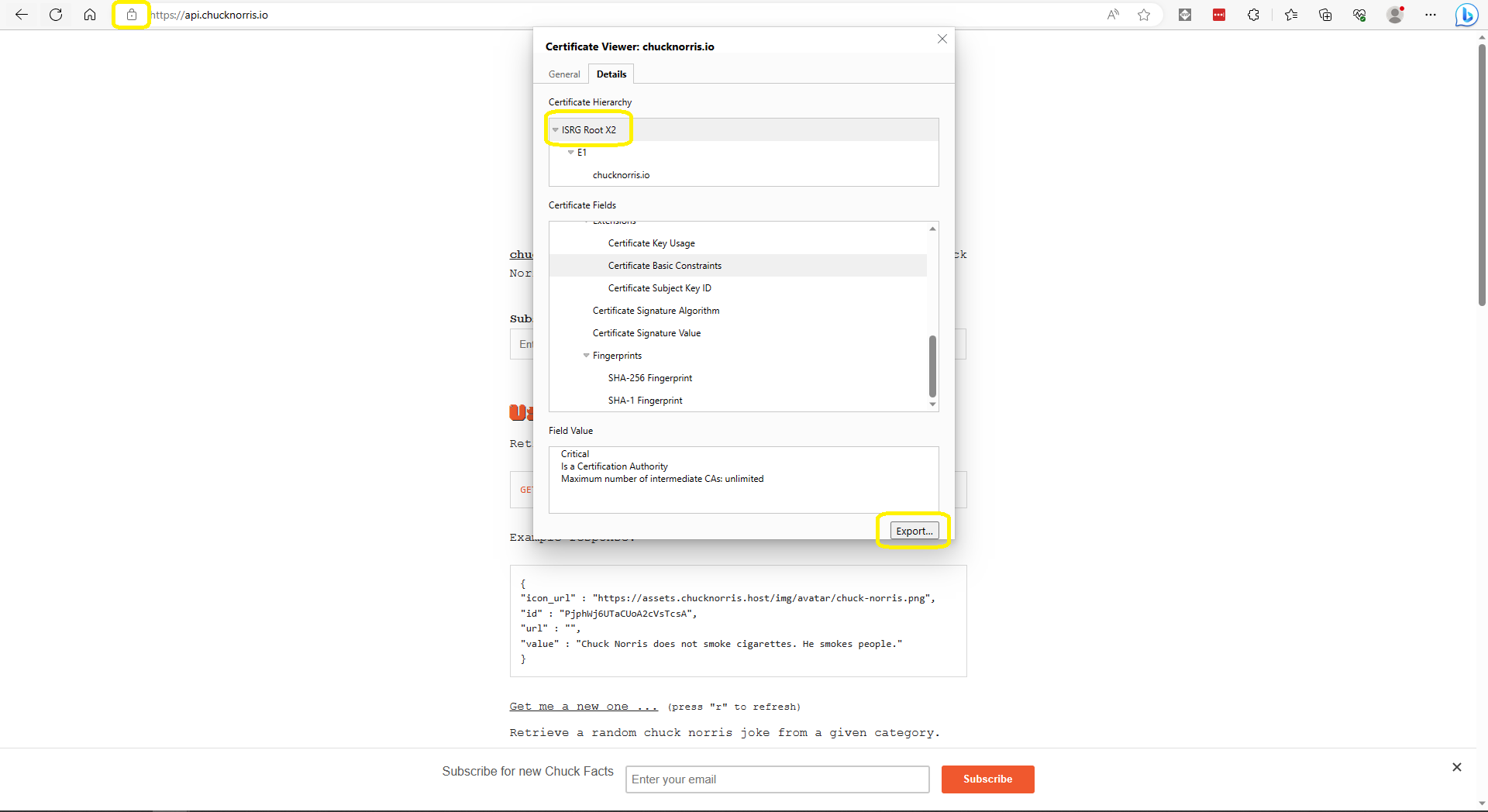
The ICNAPI supports HTTPS requests so I used the Micrsoft Edgium Certificate Viewer to download the Let’s Encrypt Internet Security Group(ISRG) Root X2 certificate.

Microsoft Edge Certificate View download

Some of the Chuck Norris facts are not suitable for school students so the request Uniform Resource Locator (URL) can be modified to ensure only “age appropriate” ones are returned.

Wireless-Tag WT32-SC01 nanoFramework getting started

Last week an ESP32 Development Board – WT32-SC01 with 3.5in 320×480 Multi-Touch capactive Screen, support Bluetooth & Wifi arrived from Elecrow. The development board was USD39.90 (June 2023) and appeared to be sourced from Wireless-Tag Technology.

WT32-SC01 packaging

The first step was to flash the WT32-SC01 with the latest version of the .NET nanoFramework for ESP32 devices. To get the device into “boot” mode I used a jumper wire to connect GPIO0 to ground before powering it up.

WT32-SC01 boot loader mode jumper

The .NET nanoFramework nanoff utility identified the device, downloaded the runtime package, and updated the device.

updating the WT32-SC01 with the nanoff utility

The next step was to run the blank NET nanoFramework sample application.

using System;
using System.Diagnostics;
using System.Threading;

namespace HelloWorld
{
    public class Program
    {
        public static void Main()
        {
            Debug.WriteLine("Hello from nanoFramework!");

            Thread.Sleep(Timeout.Infinite);

            // Browse our samples repository: https://github.com/nanoframework/samples
            // Check our documentation online: https://docs.nanoframework.net/
            // Join our lively Discord community: https://discord.gg/gCyBu8T
        }
    }
}

Microsoft Visual Studio 2022 displaying output of .NET nanoFramework Blank application

The WT32-SC01 doesn’t have a user LED so I modified the .NET nanoFramework blinky sample to flash the Liquid Crystal Display(LCD) backlight.

//
// Copyright (c) .NET Foundation and Contributors
// See LICENSE file in the project root for full license information.
//

using System.Device.Gpio;
using System;
using System.Threading;
using nanoFramework.Hardware.Esp32;

namespace Blinky
{
    public class Program
    {
        private static GpioController s_GpioController;
        public static void Main()
        {
            s_GpioController = new GpioController();

            // IO23 is LCD backlight
            GpioPin led = s_GpioController.OpenPin(Gpio.IO23,PinMode.Output ); 

            led.Write(PinValue.Low);

            while (true)
            {
                led.Toggle();
                Thread.Sleep(125);
                led.Toggle();
                Thread.Sleep(125);
                led.Toggle();
                Thread.Sleep(125);
                led.Toggle();
                Thread.Sleep(525);
            }
        }
    }
}

The

Flashing WT32-SC01 LCD backlight

Next steps getting the LCD+Touch panel and Wifi working

.NET nanoFramework RAK2305

The RAKwireless RAK2305 WisBlock WiFi Interface Module (WisBlock Wireless-IO Slot) is based on an Expressif ESP32 processor which is supported by the .NET nanoFramework. The first step was to solder some headers onto the RAK2305 so I could connect an FTDI module to get Universal Serial Bus(USB) connectivity.

RAK2305 + FTDI Test

After a small delay the RAK2305 appeared in Windows Device Manager on COM4

My first attempt to “flash” the RAK2305 with the nano Firmware Flasher(nanoff) failed

nanoff flashing failure

The RAK2305 Low Level Developer documentation described how to upload software developed with the Arduino tools by putting the ESP32 into “bootloader mode”. This is done by connecting (with the white jumper) the GPIO0 and GND pins on J14, and pressing the reset button.


nanoff flashing success

The first step with any embedded development project is to flash a Light Emitting Diode(LED)….

The RAK2305 has has one onboard LED(TEST_LED) attached to IO18 which I added to the .NET nanoFramework Blinky sample.

//
// Copyright (c) .NET Foundation and Contributors
// See LICENSE file in the project root for full license information.
//
//
using System;
using System.Device.Gpio;
using System.Threading;
using nanoFramework.Hardware.Esp32;

namespace Blinky
{
   public class Program
   {
      private static GpioController s_GpioController;

      public static void Main()
      {
         s_GpioController = new GpioController();

         // pick a board, uncomment one line for GpioPin; default is STM32F769I_DISCO

         // DISCOVERY4: PD15 is LED6 
         //GpioPin led = s_GpioController.OpenPin(PinNumber('D', 15), PinMode.Output);

         // ESP32 DevKit: 4 is a valid GPIO pin in, some boards like Xiuxin ESP32 may require GPIO Pin 2 instead.
         //GpioPin led = s_GpioController.OpenPin(4, PinMode.Output);

         // FEATHER S2: 
         //GpioPin led = s_GpioController.OpenPin(13, PinMode.Output);

         // F429I_DISCO: PG14 is LEDLD4 
         //GpioPin led = s_GpioController.OpenPin(PinNumber('G', 14), PinMode.Output);

         // NETDUINO 3 Wifi: A10 is LED onboard blue
         //GpioPin led = s_GpioController.OpenPin(PinNumber('A', 10), PinMode.Output);

         // QUAIL: PE15 is LED1  
         //GpioPin led = s_GpioController.OpenPin(PinNumber('E', 15), PinMode.Output);

         // STM32F091RC: PA5 is LED_GREEN
         //GpioPin led = s_GpioController.OpenPin(PinNumber('A', 5), PinMode.Output);

         // STM32F746_NUCLEO: PB75 is LED2
         //GpioPin led = s_GpioController.OpenPin(PinNumber('B', 7), PinMode.Output);

         //STM32F769I_DISCO: PJ5 is LD2
         //GpioPin led = s_GpioController.OpenPin(PinNumber('J', 5), PinMode.Output);

         // ST_B_L475E_IOT01A: PB14 is LD2
         //GpioPin led = s_GpioController.OpenPin(PinNumber('B', 14), PinMode.Output);

         // STM32L072Z_LRWAN1: PA5 is LD2
         //GpioPin led = s_GpioController.OpenPin(PinNumber('A', 5), PinMode.Output);

         // TI CC13x2 Launchpad: DIO_07 it's the green LED
         //GpioPin led = s_GpioController.OpenPin(7, PinMode.Output);

         // TI CC13x2 Launchpad: DIO_06 it's the red LED  
         //GpioPin led = s_GpioController.OpenPin(6, PinMode.Output);

         // ULX3S FPGA board: for the red D22 LED from the ESP32-WROOM32, GPIO5
         //GpioPin led = s_GpioController.OpenPin(5, PinMode.Output);

         // Silabs SLSTK3701A: LED1 PH14 is LLED1
         //GpioPin led = s_GpioController.OpenPin(PinNumber('H', 14), PinMode.Output);

         // RAK11200 on RAK5005
         //GpioPin led = s_GpioController.OpenPin(Gpio.IO12, PinMode.Output); // LED1 Green
         //GpioPin led = s_GpioController.OpenPin(Gpio.IO02, PinMode.Output); // LED2 Blue

         // RAK11200 on RAK19001 needs battery connected or power switch in rechargeable position.
         //GpioPin led = s_GpioController.OpenPin(Gpio.IO12, PinMode.Output); // LED1 Green
         //GpioPin led = s_GpioController.OpenPin(Gpio.IO02, PinMode.Output); // LED2 Blue

         // RAK2305 
         //GpioPin led = s_GpioController.OpenPin(Gpio.IO18, PinMode.Output); // LED Green (Test LED) on device

         // RAK2305 On 5005 throws exceptions
         //GpioPin led = s_GpioController.OpenPin(Gpio.IO34, PinMode.Output); // LED1 Green
         //GpioPin led = s_GpioController.OpenPin(Gpio.IO35, PinMode.Output); // LED2 Blue

         // RAK2305 On 17001 throws exceptions
         //GpioPin led = s_GpioController.OpenPin(Gpio.IO34, PinMode.Output); // LED1 Green
         //GpioPin led = s_GpioController.OpenPin(Gpio.IO35, PinMode.Output); // LED2 Blue

         led.Write(PinValue.Low);

         while (true)
         {
            led.Toggle();
            Thread.Sleep(125);
            led.Toggle();
            Thread.Sleep(125);
            led.Toggle();
            Thread.Sleep(125);
            led.Toggle();
            Thread.Sleep(525);
         }
      }

      static int PinNumber(char port, byte pin)
      {
         if (port < 'A' || port > 'J')
            throw new ArgumentException();

         return ((port - 'A') * 16) + pin;
      }
   }
}

I added the RAK2305 configuration to my version of the nanoFramework Blinky sample and could reliably flash the onboard LED.

.NET nanoFramework RAK11200 – I2C SHT3C & SHT31

The RAKwireless RAK11200 WisBlock WiFi Module module is based on an Expressif ESP32 processor which is supported by the .NET nanoFramework and I wanted to explore the different ways Inter-Integrated Circuit(I2C) devices could be connected.

The RAK11200 WisBlock WiFi Module has two I2C ports and on the RAK5005 WisBlock Base Board the Wisblock Sensor, and RAK1920 WisBlock Sensor Adapter Module Grove Socket are connected to I2C1.

RAK11200 Schematic

The I2C1 the SDA(serial data) and SCL(serial clock line) have to be mapped to physical pins on the RAK11200 WisBlock WiFi Module using the nanoFramework ESP32 support NuGet. package

                Configuration.SetPinFunction(Gpio.IO04, DeviceFunction.I2C1_DATA);
                Configuration.SetPinFunction(Gpio.IO05, DeviceFunction.I2C1_CLOCK)

The first sample project uses a RAK1901 SHTC3 WisBlock Sensor because it plugs into the RAK5005 WisBlock Base Board.

RAK5005 Baseboard, RAK1901 Sensor and RAK11200 Core WisBlock modules
public static void Main()
{
    Debug.WriteLine("devMobile.IoT.RAK.Wisblock.SHTC3 starting");

    try
    {
        Configuration.SetPinFunction(Gpio.IO04, DeviceFunction.I2C1_DATA);
        Configuration.SetPinFunction(Gpio.IO05, DeviceFunction.I2C1_CLOCK);

        I2cConnectionSettings settings = new(1, Shtc3.DefaultI2cAddress);

        using (I2cDevice device = I2cDevice.Create(settings))
        using (Shtc3 shtc3 = new(device))
        {
            while (true)
            {
                if (shtc3.TryGetTemperatureAndHumidity(out var temperature, out var relativeHumidity))
                {
                    Debug.WriteLine($"Temperature {temperature.DegreesCelsius:F1}°C  Humidity {relativeHumidity.Value:F0}%");
                }

                Thread.Sleep(10000);
            }
        }
    }
    catch (Exception ex)
    {
        Debug.WriteLine($"SHTC3 initialisation or read failed {ex.Message}");

        Thread.Sleep(Timeout.Infinite);
    }
}
Visual Studio Output window displaying SHT3C temperature & humidity values

The second sample uses a Seeedstudio Grove – Temperature & Humidity Sensor (SHT31) pluged into a RAK1920 Sensor Adapter for Click, QWIIC and Grove Modules.

RAK5005 Baseboard, RAK1920 Sensor, RAK11200 Core WisBlock modules and Seeedstudio Grove SHT31
public static void Main()
{
    Debug.WriteLine("devMobile.IoT.RAK.Wisblock.SHT31 starting");

    try
    {
        Configuration.SetPinFunction(Gpio.IO04, DeviceFunction.I2C1_DATA);
        Configuration.SetPinFunction(Gpio.IO05, DeviceFunction.I2C1_CLOCK);

        I2cConnectionSettings settings = new(1, (byte)I2cAddress.AddrLow);

        using (I2cDevice device = I2cDevice.Create(settings))
        using (Sht3x sht31 = new(device))
        {

            while (true)
            {
                var temperature = sht31.Temperature;
                var relativeHumidity = sht31.Humidity;

                Debug.WriteLine($"Temperature {temperature.DegreesCelsius:F1}°C  Humidity {relativeHumidity.Value:F0}%");

                Thread.Sleep(10000);
            }
        }
    }
    catch (Exception ex)
    {
        Debug.WriteLine($"SHT31 initialisation or read failed {ex.Message}");

        Thread.Sleep(Timeout.Infinite);
     }
}
Visual Studio Output window displaying SHT31 temperature & humidity values

The SHTC3 and SHT31 sensors were used because they both have nanoFramework.IoTDevice library support.

.NET nanoFramework RAK11200

The RAKwireless RAK11200 WisBlock WiFi Module module is based on an Expressif ESP32 processor which is supported by the .NET nanoFramework. The first step was to mount the RAK11200 on a RAK5005 WisBlock Base Board to get Universal Serial Bus(USB) connectivity.

RAK11200 Mounted on RAK5005 base board

My first attempt “flash” the RAK11200 with the nano Firmware Flasher(nanoff) failed badly

nanoff flashing failure

The RAK11200 documentation described how to upload software developed with the Arduino tools by putting the ESP32 into “bootloader mode” by connecting the BOOT0 and GND pins, then pressing the reset button.

RAK11200 BOOT0 & GND pins connected to

After some “trial and error” the download process worked pretty reliably…

nanoff flashing success

The first step with any embedded development project is to flash a Light Emitting Diode(LED)….

RAK11200 Schematic

The RAK11200 has two LEDs, a blue attached to IO02 and a green one attached to IO12.

//
// Copyright (c) .NET Foundation and Contributors
// See LICENSE file in the project root for full license information.
//
//
using System;
using System.Device.Gpio;
using System.Threading;
using nanoFramework.Hardware.Esp32;

namespace Blinky
{
   public class Program
   {
      private static GpioController s_GpioController;
      public static void Main()
      {
         s_GpioController = new GpioController();

         // pick a board, uncomment one line for GpioPin; default is STM32F769I_DISCO

         // DISCOVERY4: PD15 is LED6 
         //GpioPin led = s_GpioController.OpenPin(PinNumber('D', 15), PinMode.Output);

         // ESP32 DevKit: 4 is a valid GPIO pin in, some boards like Xiuxin ESP32 may require GPIO Pin 2 instead.
         //GpioPin led = s_GpioController.OpenPin(4, PinMode.Output);

         // FEATHER S2: 
         //GpioPin led = s_GpioController.OpenPin(13, PinMode.Output);

         // F429I_DISCO: PG14 is LEDLD4 
         //GpioPin led = s_GpioController.OpenPin(PinNumber('G', 14), PinMode.Output);

         // NETDUINO 3 Wifi: A10 is LED onboard blue
         //GpioPin led = s_GpioController.OpenPin(PinNumber('A', 10), PinMode.Output);

         // QUAIL: PE15 is LED1  
         //GpioPin led = s_GpioController.OpenPin(PinNumber('E', 15), PinMode.Output);

         // STM32F091RC: PA5 is LED_GREEN
         //GpioPin led = s_GpioController.OpenPin(PinNumber('A', 5), PinMode.Output);

         // STM32F746_NUCLEO: PB75 is LED2
         //GpioPin led = s_GpioController.OpenPin(PinNumber('B', 7), PinMode.Output);

         //STM32F769I_DISCO: PJ5 is LD2
         //GpioPin led = s_GpioController.OpenPin(PinNumber('J', 5), PinMode.Output);

         // ST_B_L475E_IOT01A: PB14 is LD2
         //GpioPin led = s_GpioController.OpenPin(PinNumber('B', 14), PinMode.Output);

         // STM32L072Z_LRWAN1: PA5 is LD2
         //GpioPin led = s_GpioController.OpenPin(PinNumber('A', 5), PinMode.Output);

         // TI CC13x2 Launchpad: DIO_07 it's the green LED
         //GpioPin led = s_GpioController.OpenPin(7, PinMode.Output);

         // TI CC13x2 Launchpad: DIO_06 it's the red LED  
         //GpioPin led = s_GpioController.OpenPin(6, PinMode.Output);

         // ULX3S FPGA board: for the red D22 LED from the ESP32-WROOM32, GPIO5
         //GpioPin led = s_GpioController.OpenPin(5, PinMode.Output);

         // Silabs SLSTK3701A: LED1 PH14 is LLED1
         //GpioPin led = s_GpioController.OpenPin(PinNumber('H', 14), PinMode.Output);

         // RAK11200 on RAK5005
         //GpioPin led = s_GpioController.OpenPin(Gpio.IO12, PinMode.Output); // LED1 Green
         //GpioPin led = s_GpioController.OpenPin(Gpio.IO02, PinMode.Output); // LED2 Blue

         // RAK11200 on RAK19001 needs battery connected or power switch in rechargeable position.
         //GpioPin led = s_GpioController.OpenPin(Gpio.IO12, PinMode.Output); // LED1 Green
         //GpioPin led = s_GpioController.OpenPin(Gpio.IO02, PinMode.Output); // LED2 Blue

         // RAK2305 
         //GpioPin led = s_GpioController.OpenPin(Gpio.IO18, PinMode.Output); // LED Green (Test LED) on device

         // RAK2305 On 5005 throws exceptions
         //GpioPin led = s_GpioController.OpenPin(Gpio.IO34, PinMode.Output); // LED1 Green
         //GpioPin led = s_GpioController.OpenPin(Gpio.IO35, PinMode.Output); // LED2 Blue

         // RAK2305 On 17001 throws exceptions
         //GpioPin led = s_GpioController.OpenPin(Gpio.IO34, PinMode.Output); // LED1 Green
         //GpioPin led = s_GpioController.OpenPin(Gpio.IO35, PinMode.Output); // LED2 Blue

         led.Write(PinValue.Low);

         while (true)
         {
            led.Toggle();
            Thread.Sleep(125);
            led.Toggle();
            Thread.Sleep(125);
            led.Toggle();
            Thread.Sleep(125);
            led.Toggle();
            Thread.Sleep(525);
         }
      }

      static int PinNumber(char port, byte pin)
      {
         if (port < 'A' || port > 'J')
            throw new ArgumentException();

         return ((port - 'A') * 16) + pin;
      }
   }
}

I added the RAK11200 configuration to my version of the nanoFramework Blinky sample and could reliably flash either of the LEDs.