The first step was to check that I could get a “battery charge” value for the RAKWireless RAK11200 WisBlock WiFi Module on a RAK19007 WisBlock Base Board to send to an Azure IoT Hub.


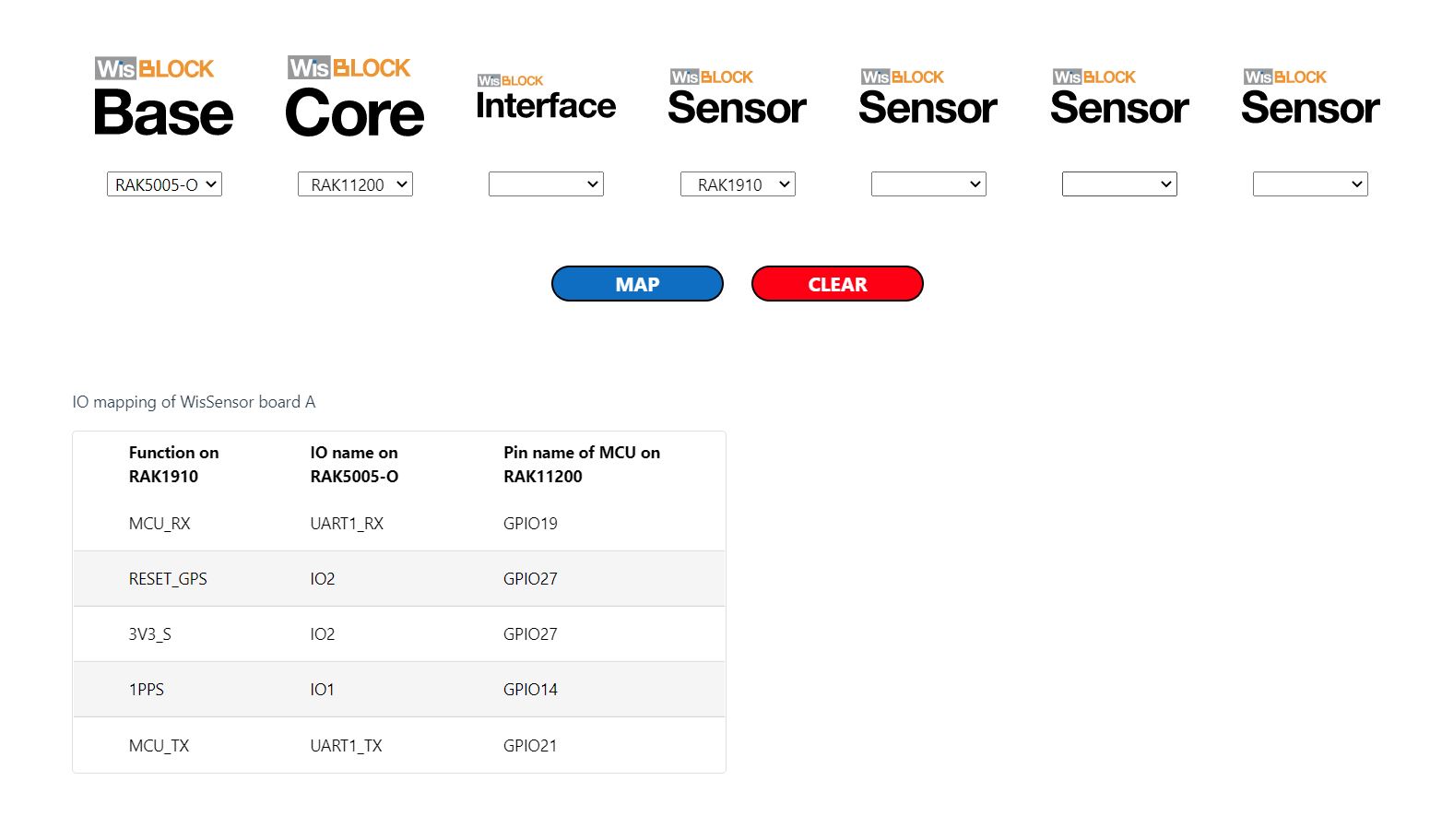
The RAK19007 WisBlock Base Board has a voltage divider (R3&R4 with output ADC_VBAT) which is connected (via R7) to pin 21(AIN0) on the CPU slot connector.
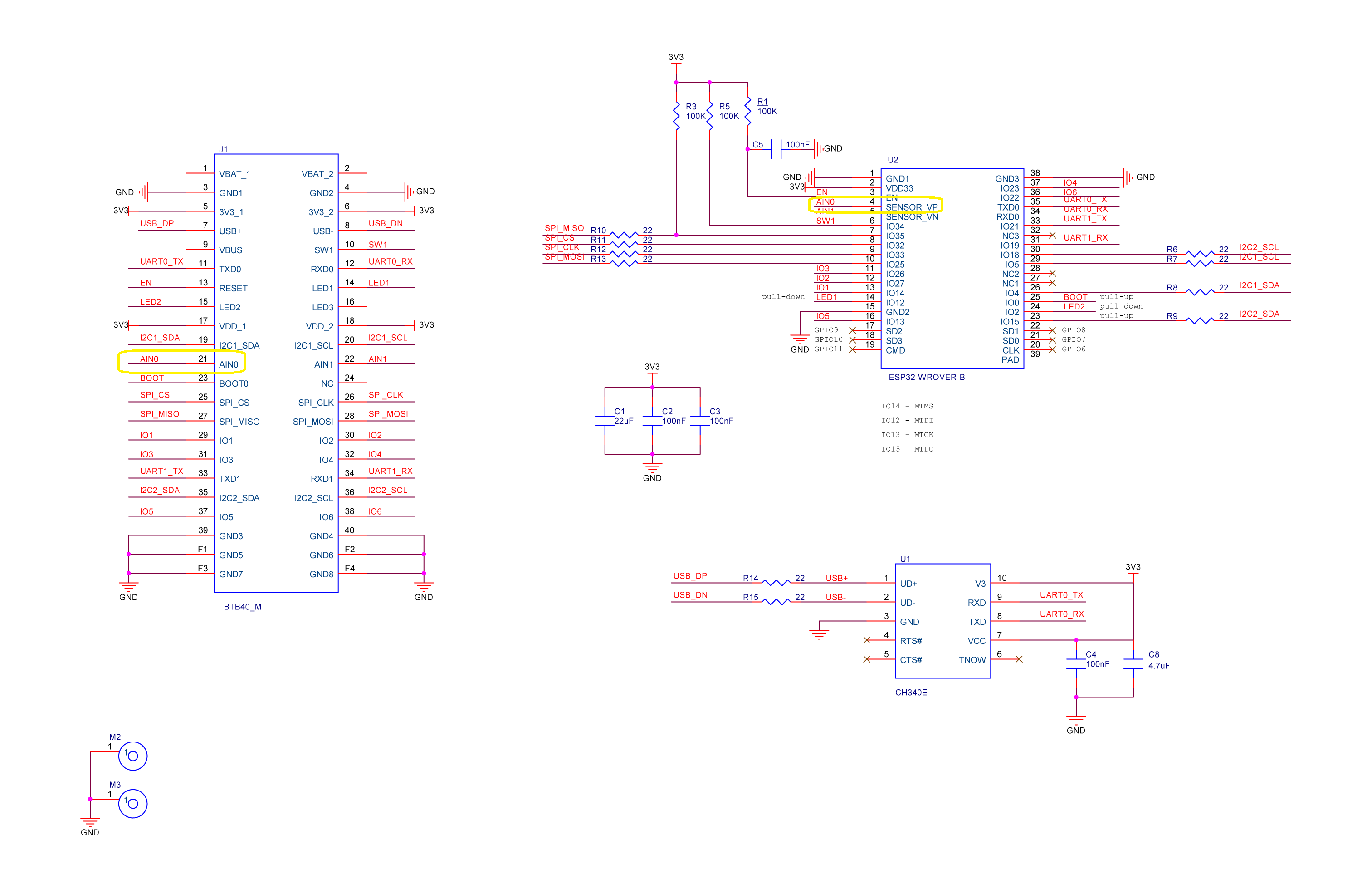
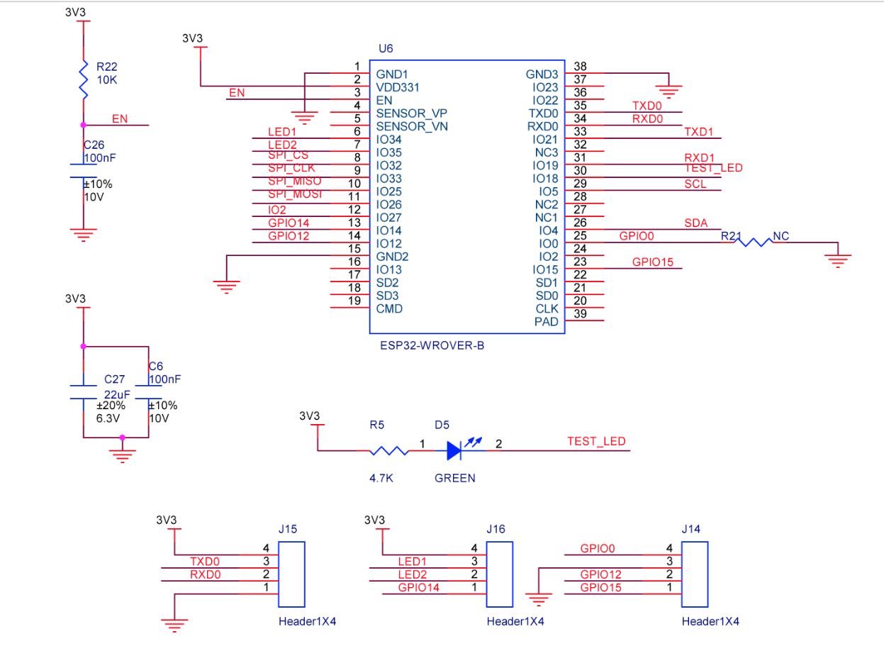
The AIN0(pin 21) of the RAK11200 WisBlock WiFi Module is connected to SENSOR_VP(pin4) of the Espressif ESP32-WROVER-B so I could measure the battery charge.

My test setup was a RAK11200 WisBlock WiFi Module, RAK19007 WisBlock Base Board, RAK1901 WisBlock Temperature and Humidity Sensor and 1200mAH Lithium Polymer (LiPo) battery which uploads temperature, humidity and battery charge telemetry to an Azure IoT Hub every 10 minutes.
I used AdcController + AdcChannel to read the AIN0 value which was then inserted in the Java Script Object Notation(JSON) telemetry payload.
public class Program
{
private const int I2cDeviceBusID = 1;
private const int AdcControllerChannel = 0;
public static void Main()
{
DateTime sasTokenValidUntilUtc = DateTime.UtcNow;
Debug.WriteLine($"{DateTime.UtcNow:HH:mm:ss} devMobile.IoT.RAK.Wisblock.AzureIoTHub.RAK11200.PowerBaseline starting");
Configuration.SetPinFunction(Gpio.IO04, DeviceFunction.I2C1_DATA);
Configuration.SetPinFunction(Gpio.IO05, DeviceFunction.I2C1_CLOCK);
if (!WifiNetworkHelper.ConnectDhcp(Config.Ssid, Config.Password, requiresDateTime: true))
{
if (NetworkHelper.HelperException != null)
{
Debug.WriteLine($"{DateTime.UtcNow:HH:mm:ss} WifiNetworkHelper.ConnectDhcp failed {NetworkHelper.HelperException}");
}
Thread.Sleep(Timeout.Infinite);
}
string uri = $"{Config.AzureIoTHubHostName}.azure-devices.net/devices/{Config.DeviceID}";
// not setting Authorization here as it will change as SAS Token refreshed
HttpClient httpClient = new HttpClient
{
SslProtocols = System.Net.Security.SslProtocols.Tls12,
HttpsAuthentCert = new X509Certificate(Config.DigiCertBaltimoreCyberTrustRoot),
BaseAddress = new Uri($"https://{uri}/messages/events?api-version=2020-03-13"),
};
I2cConnectionSettings settings = new(I2cDeviceBusID, Shtc3.DefaultI2cAddress);
I2cDevice device = I2cDevice.Create(settings);
Shtc3 shtc3 = new(device);
AdcController adcController = new AdcController();
AdcChannel batteryChargeAdcChannel = adcController.OpenChannel(AdcControllerChannel);
string sasToken = "";
while (true)
{
DateTime standardisedUtcNow = DateTime.UtcNow;
Debug.WriteLine($"{DateTime.UtcNow:HH:mm:ss} Azure IoT Hub device {Config.DeviceID} telemetry update start");
if (sasTokenValidUntilUtc <= standardisedUtcNow)
{
sasTokenValidUntilUtc = standardisedUtcNow.Add(Config.SasTokenRenewEvery);
sasToken = SasTokenGenerate(uri, Config.Key, sasTokenValidUntilUtc);
Debug.WriteLine($" Renewing SAS token for {Config.SasTokenRenewFor} valid until {sasTokenValidUntilUtc:HH:mm:ss dd-MM-yy}");
}
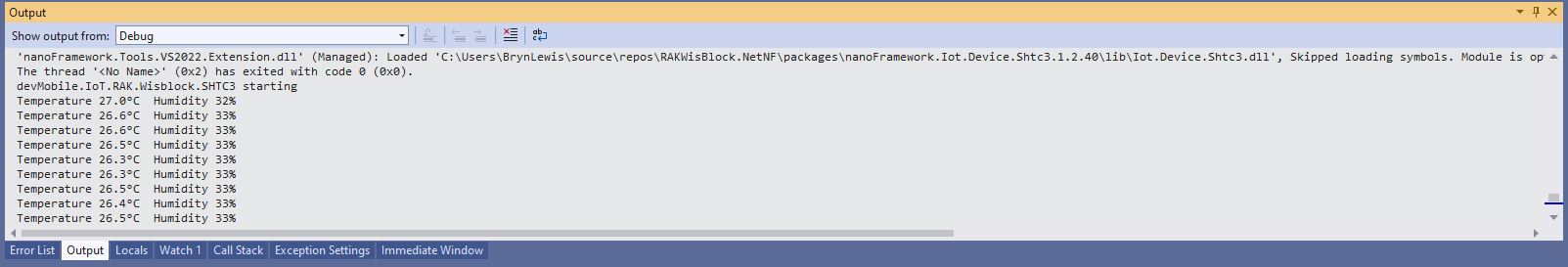
if (!shtc3.TryGetTemperatureAndHumidity(out var temperature, out var relativeHumidity))
{
Debug.WriteLine($" Temperature and Humidity read failed");
continue;
}
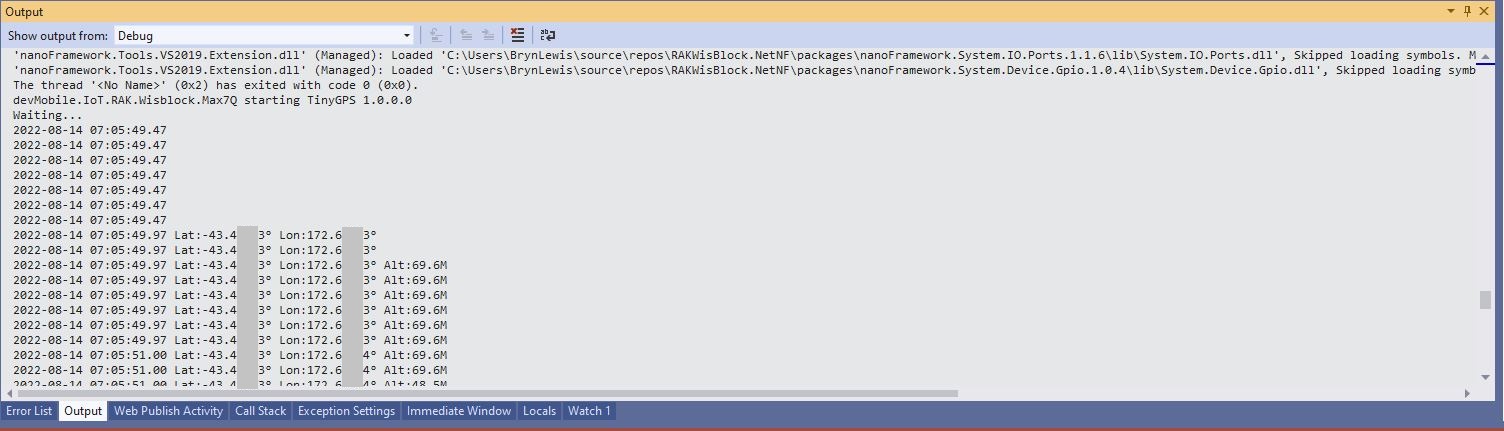
double batteryCharge = batteryChargeAdcChannel.ReadRatio() * 100.0;
Debug.WriteLine($" Temperature {temperature.DegreesCelsius:F1}°C Humidity {relativeHumidity.Value:F0}% BatteryCharge {batteryCharge:F1}%");
string payload = $"{{\"RelativeHumidity\":{relativeHumidity.Value:F0},\"Temperature\":{temperature.DegreesCelsius.ToString("F1")}, \"BatteryCharge\":{batteryCharge:F1}}}";
try
{
using (HttpContent content = new StringContent(payload))
{
content.Headers.Add("Authorization", sasToken);
using (HttpResponseMessage response = httpClient.Post("", content))
{
Console.WriteLine($"{DateTime.UtcNow:HH:mm:ss} Response code:{response.StatusCode}");
response.EnsureSuccessStatusCode();
}
}
}
catch (Exception ex)
{
Debug.WriteLine($"{DateTime.UtcNow:HH:mm:ss} Azure IoT Hub POST failed:{ex.Message} {ex?.InnerException?.Message}");
}
Debug.WriteLine($"{DateTime.UtcNow:HH:mm:ss} Azure IoT Hub telemetry update done");
Thread.Sleep(Config.TelemetryUploadInterval);
}
}
...
}
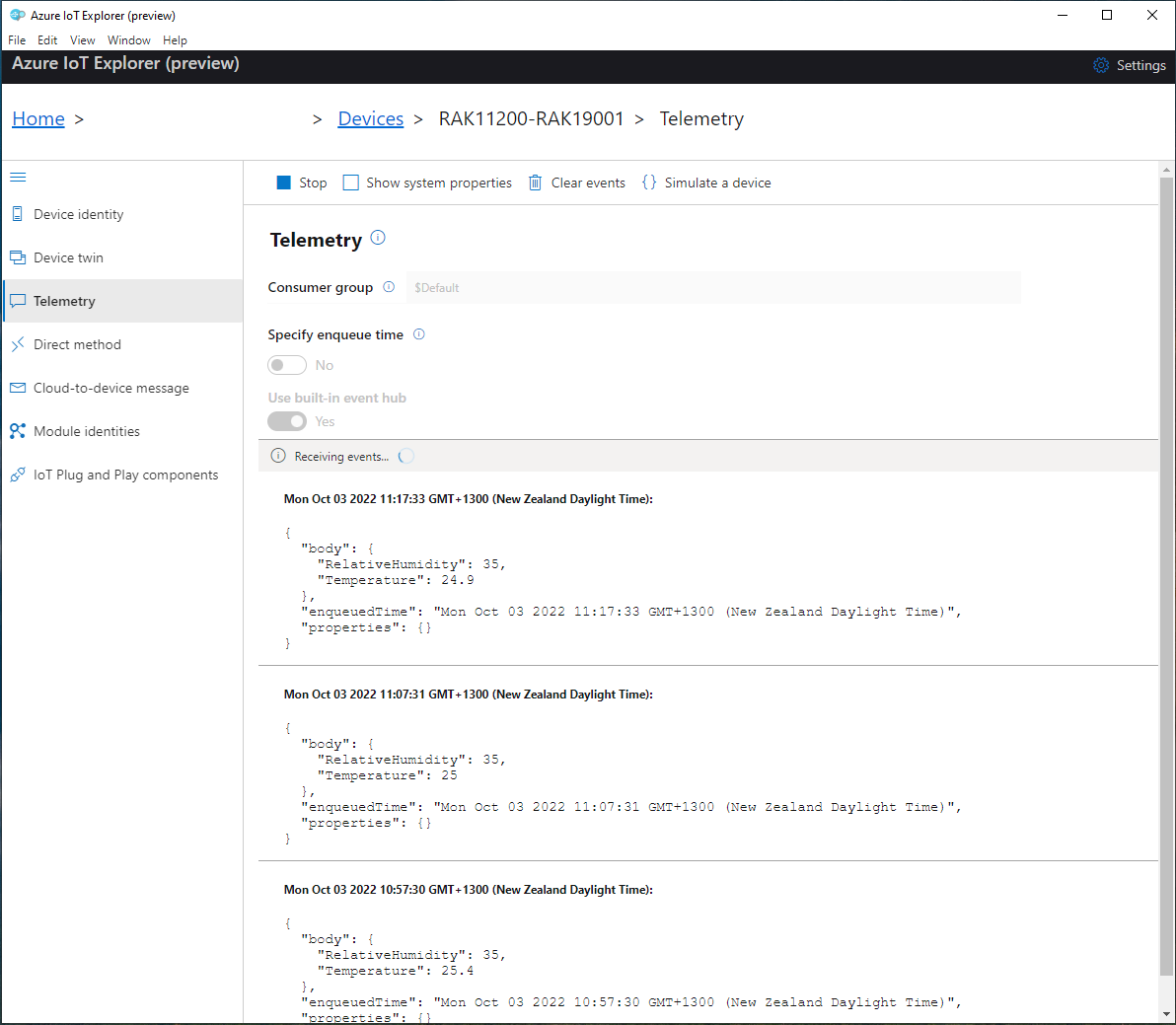
I used Azure IoT Explorer to monitor the Azure IoT Hub device telemetry to see how BatteryCharge value decreased to a level where the device wouldn’t transmit.

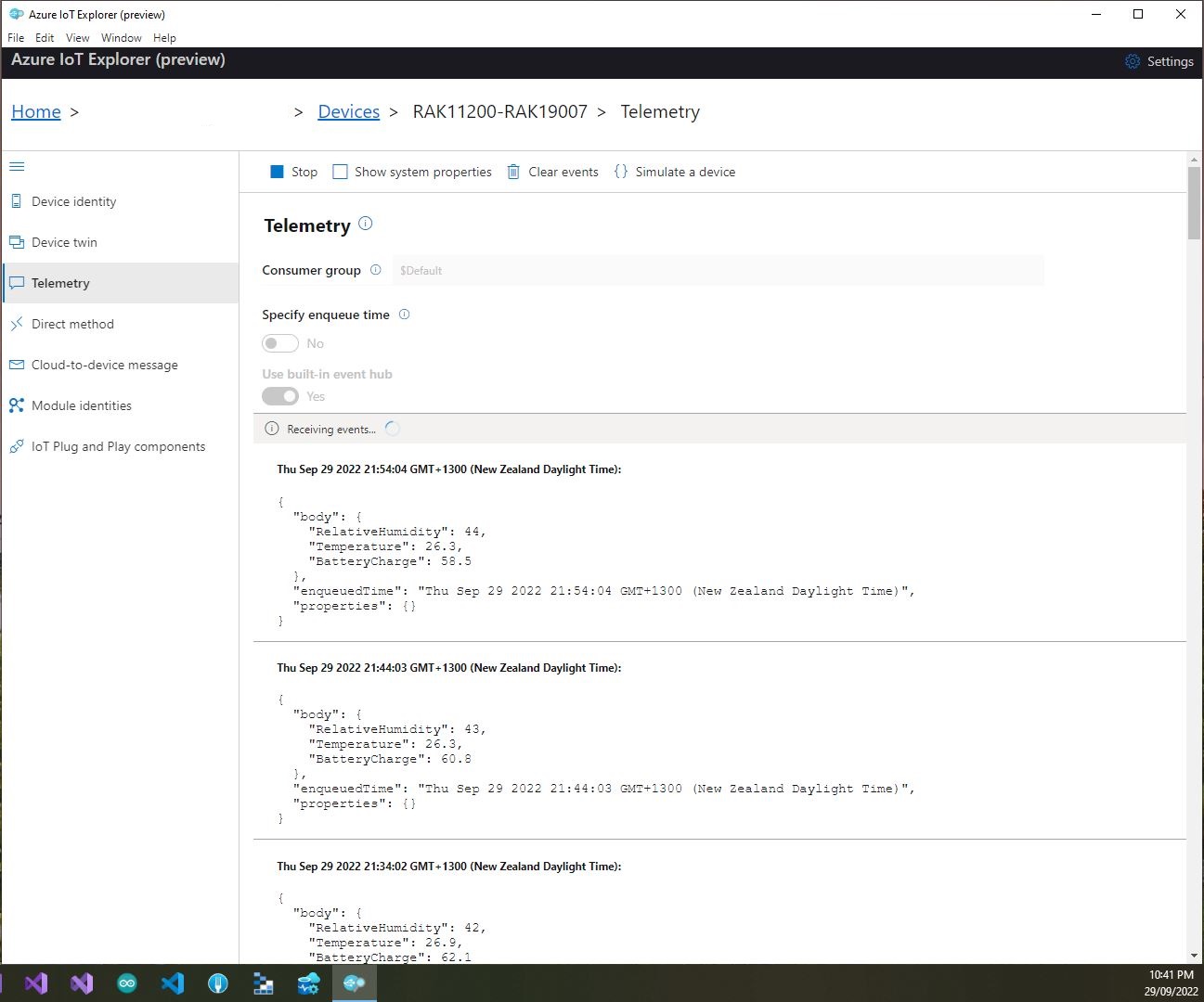
With no use of the “power conservation” functionality of the ESP32-WROVER-B powered by a 1200mAH battery the device ran for approximately 11hrs (11:00am – 10:00pm).

I think the RAK2305 will not be able to measure “battery charge” as the SENSOR_VP pin on the Espressif ESP32-WROVER-B is not connected to AIN0.