Random wanderings through Microsoft Azure esp. PaaS plumbing, the IoT bits, AI on Micro controllers, AI on Edge Devices, .NET nanoFramework, .NET Core on *nix and ML.NET+ONNX
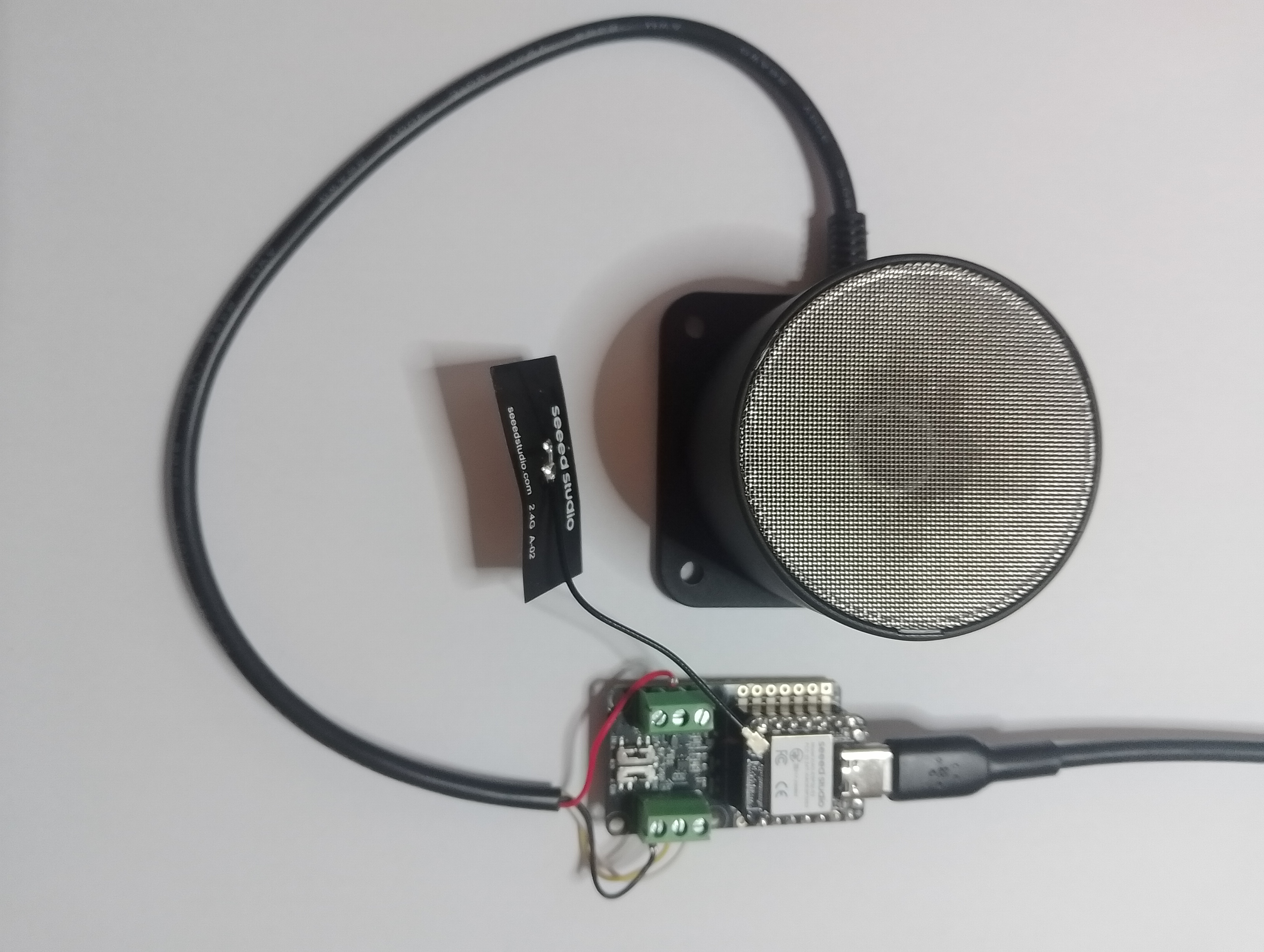
// XIAO ESP32S3 + RS485 breakout + Seeed 101991042 (RS-485 Modbus RTU)
// Reads: 0x0100 (calculated distance, mm), 0x0101 (real-time distance, mm),
// 0x0102 (temperature, 0.1°C). Can write 0x0200 (slave address).
// Serial: 9600 8N1 per datasheet. (Default slave addr = 0x01)
//Iot.Device.Modbus (namespace Iot.Device.Modbus.Client)
//using Iot.Device.Modbus;
using Iot.Device.Modbus.Client;
//using Microsoft.Extensions.Logging;
using nanoFramework.Hardware.Esp32;
//using nanoFramework.Logging.Debug;
using System;
using System.Diagnostics;
using System.IO.Ports;
using System.Threading;
namespace SeeedRS485500cmUltrasonicLevelSensor
{
public class Program
{
// === Sensor Modbus params (from Seeed datasheet) ===
private const byte SlaveAddress = 0x01; // default
private const ushort RegCalcDistance = 0x0100;// mm, ~500ms processing
//private const ushort RegRealDistance = 0x0101;// mm, ~100ms
private const ushort RegTemperature = 0x0102;// INT16, 0.1°C units
private const ushort RegSlaveAddress = 0x0200;// R/W address register
public static void Main()
{
ModbusClient _client;
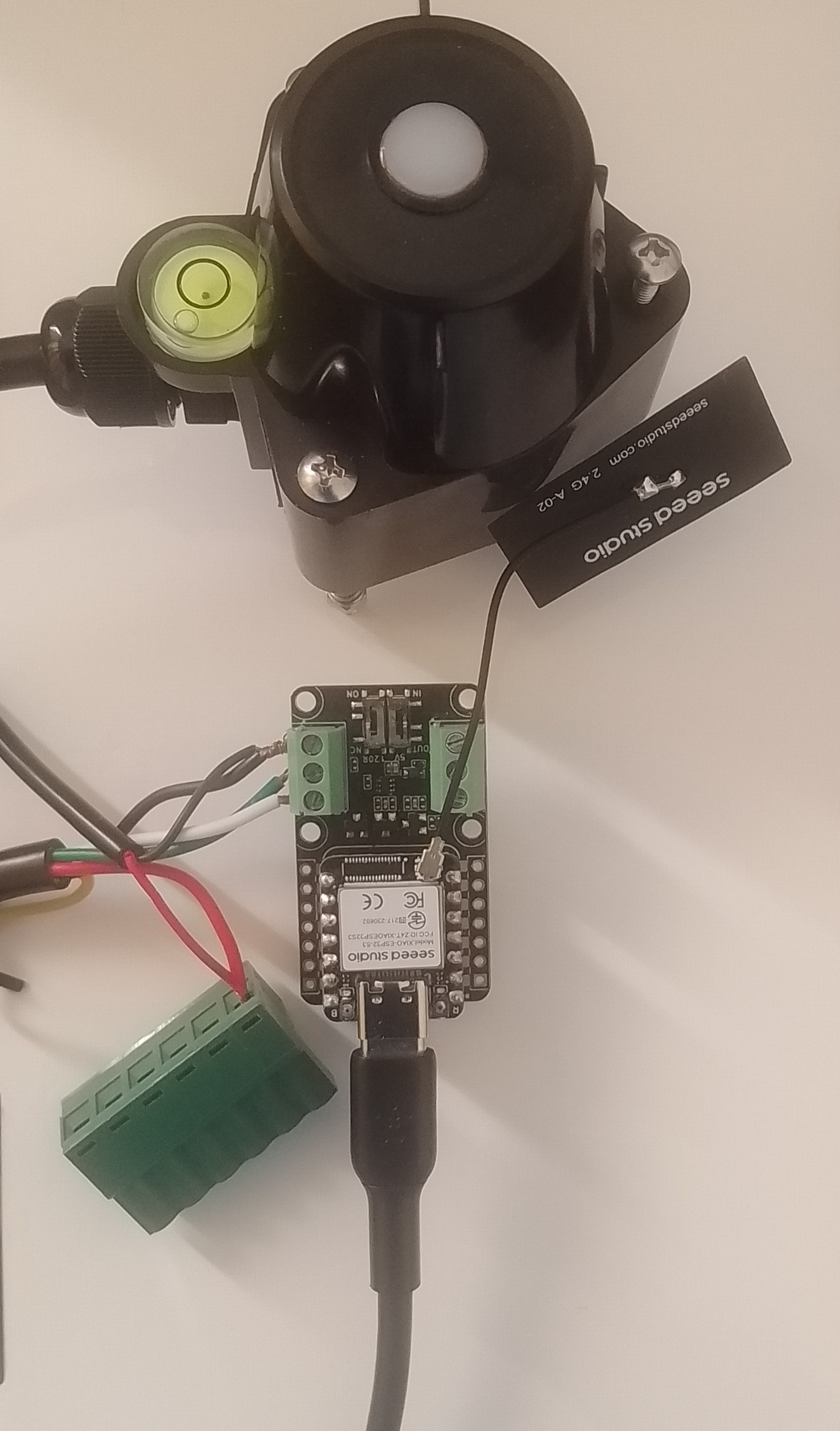
Console.WriteLine("Modbus: Seeed SKU101991042 Starting");
Configuration.SetPinFunction(Gpio.IO06, DeviceFunction.COM2_RX);
Configuration.SetPinFunction(Gpio.IO05, DeviceFunction.COM2_TX);
// This port number is a bit weird, need to double check in RS485 Sender/Receiver apps
Configuration.SetPinFunction(Gpio.IO03, DeviceFunction.COM2_RTS);
var ports = SerialPort.GetPortNames();
Debug.WriteLine("Available ports: ");
foreach (string port in ports)
{
Debug.WriteLine($" {port}");
}
using (_client = new ModbusClient("COM2"))
{
_client.ReadTimeout = _client.WriteTimeout = 2000;
//_client.Logger = new DebugLogger("ModbusClient")
//{
// MinLogLevel = LogLevel.Debug
//};
while (true)
{
try
{
// 0x0100 Calculated distance (mm). Takes ~500ms to compute per datasheet.
short[] calc = _client.ReadHoldingRegisters(SlaveAddress, RegCalcDistance, 1);
ushort calcMm = (ushort)calc[0];
float calcCm = calcMm / 10.0f;
Console.WriteLine($"Calculated distance: {calcMm} mm ({calcCm:F1} cm)");
/*
// 0x0101 Real-time distance (mm). Faster ~100ms response.
short[] real = _client.ReadHoldingRegisters(SlaveAddress, RegRealDistance, 1);
short realMm = real[0];
float realCm = realMm / 10.0f;
Console.WriteLine($"Real-time distance: {realMm} mm ({realCm:F1} cm)");
*/
// 0x0102 Temperature (INT16, 0.1°C)
short[] temp = _client.ReadHoldingRegisters(SlaveAddress, RegTemperature, 1);
short tempRaw = unchecked((short)temp[0]); // signed per datasheet
float tempC = tempRaw / 10.0f;
Console.WriteLine($"Temperature: {tempC:F1} °C");
}
catch (Exception ex)
{
Console.WriteLine($"Modbus read failed: {ex.Message}");
}
Thread.Sleep(10000);
}
}
}
}
}
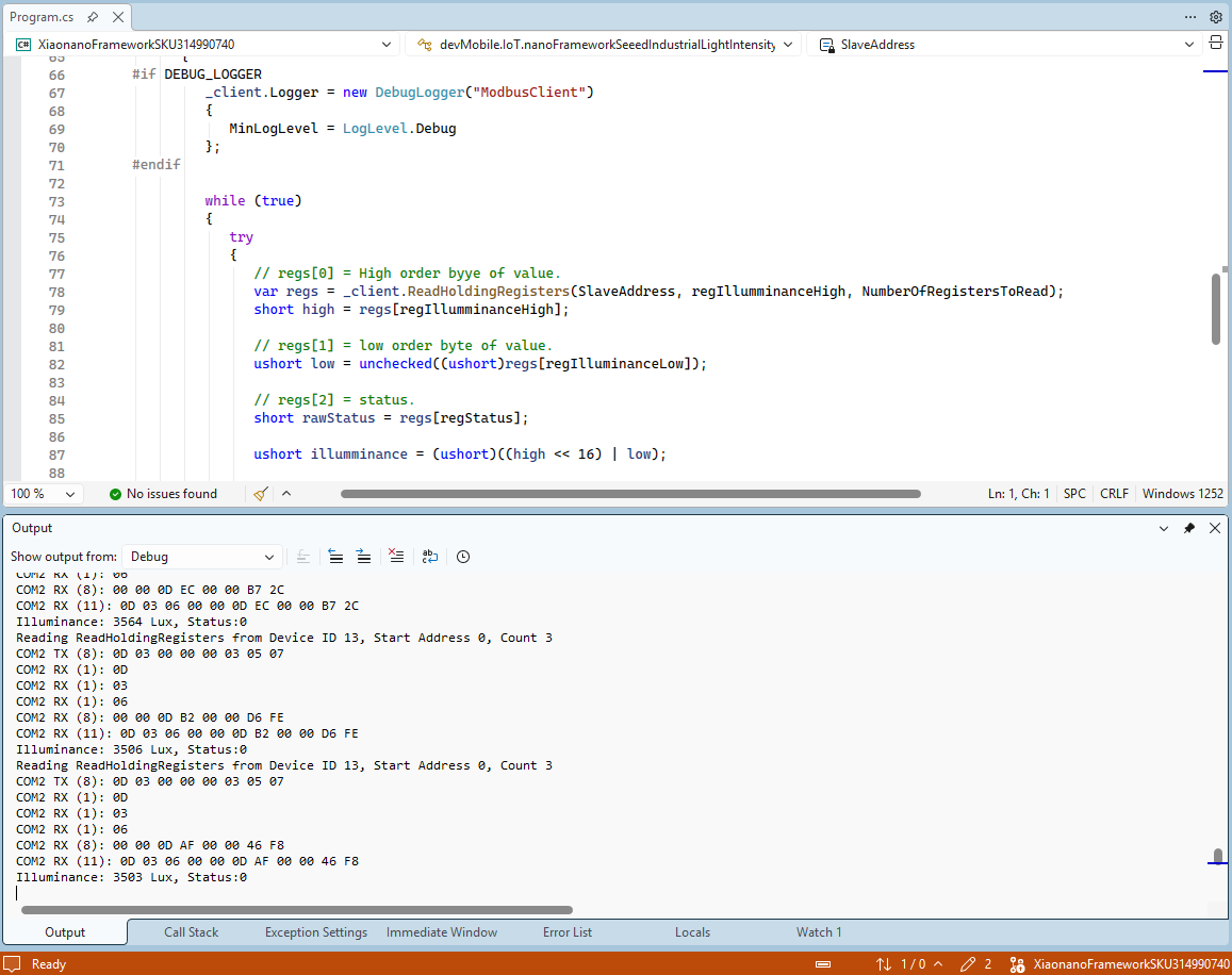
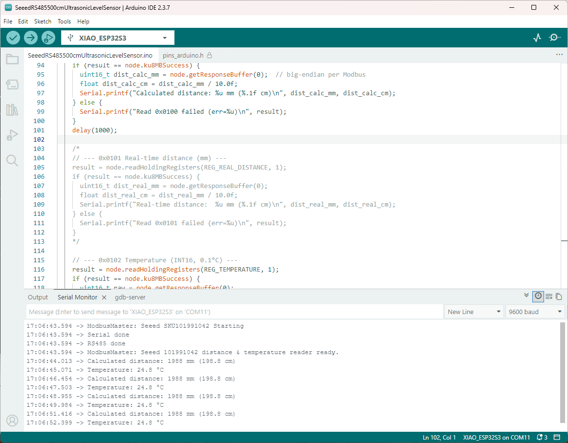
The nanoFramework logging support made debugging connectivity issues much faster. So much so I started with the nanoFramework application then progressed to the Arduino version.
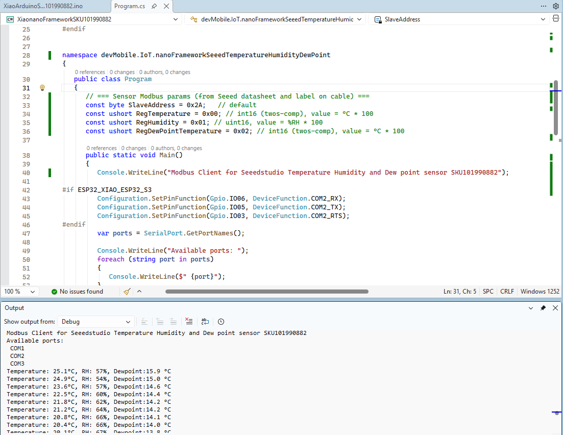
I had to add a short delay between each Modbus sensor value read to stop timeout errors.