Code Camp Christchurch 2014

The Hardware

Flash an LED

OutputPort led = new OutputPort(Pins.ONBOARD_LED, false);
while ( true)
{
   Led.Write(!Led.Read())
   Thread.Sleep(500)
}

Digital Input – Polled

InputPort button = new InputPort(Pins.ONBOARD_SW1, false, Port.ResistorMode.Disabled);
OutputPort led = new OutputPort(Pins.ONBOARD_LED, false);
while (true)
{
   led.Write(button.Read());
   Thread.Sleep(1000);
}

Digital Input – Interrupt

static OutputPort interuptled = new OutputPort(Pins.ONBOARD_LED, false);
InterruptPort button = new InterruptPort(Pins.ONBOARD_SW1, false, Port.ResistorMode.Disabled, Port.InterruptMode.InterruptEdgeHigh);
button.OnInterrupt += new NativeEventHandler(button_OnInterrupt);

Thread.Sleep(Timeout.Infinite);

static void button_OnInterrupt(uint data1, uint data2, DateTime time)
{
   interuptled.Write(!interuptled.Read());
}

Analog Input

AnalogInput Sensor = new AnalogInput(Cpu.AnalogChannel.ANALOG_0);
while ( true)
{
   Debug.Print( "Value " + Sensor.Read().ToString("F2"));
   Thread.Sleep(500);
}

Pulse Width Modulation Output

AnalogInput brightness = new AnalogInput(AnalogChannels.ANALOG_PIN_A0);
PWM led = new PWM(PWMChannels.PWM_PIN_D5, 1000, 0.0, false);

led.Start();
while (true)
{
   Debug.Print("Brightness " + led.DutyCycle.ToString("F2"));
   led.DutyCycle = brightness.Read();
   Thread.Sleep(500);
}
led.Stop();

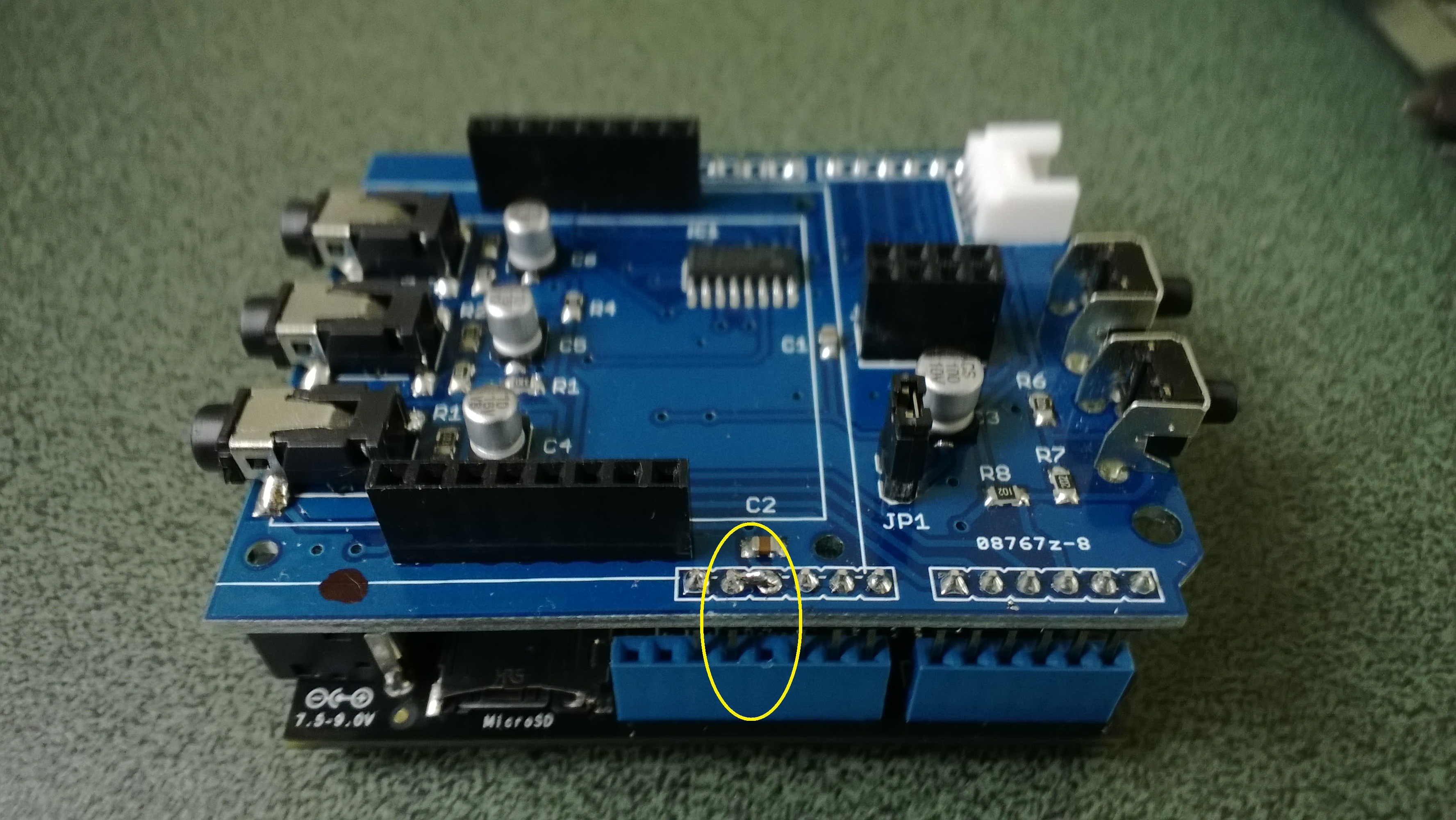
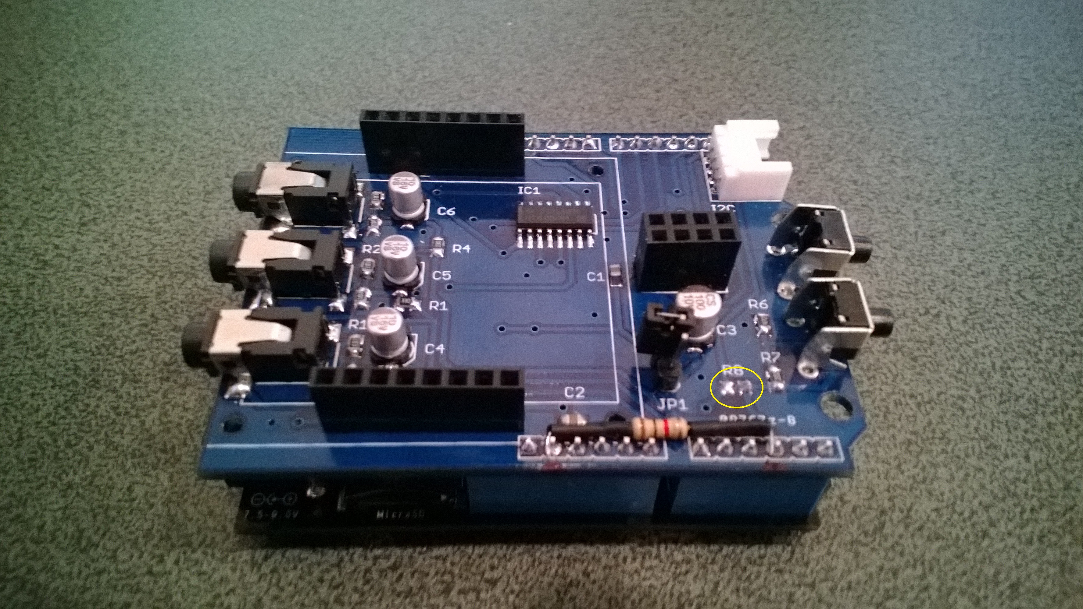
Power Consumption Monitor

Developing the software for the Energy Monitor Shield

Robot

Developing the software

  • Determine the distance to objects
  • Control the speed & direction of the motors using a Motor Shield Driver
  • Basic obstacle avoidance
  • Avoid obstacles using a state machine
  • Fine tune the motor speeds using a rotary encoder
  • Connect the GPS
  • Upload the position information to Xively

Heart Rate Monitor

Developing the software

  • Read the buttons using an AnalogInput
  • Count the number of button presses using an InterruptPort and a Timer
  • Determine the pulse rate in BPM by counting
  • Determine the average pulse rate in BPM
  • Display and manage the pulse rate info on the DFRobot 16×2 Lcd Shield
  • Upload the pulse rate information to xively


Energy Monitor Shield Noise Reduction

In a couple of previous posts the noise on the Netduino AnalogInput and the impact of this on the RMS current measurement was discussed. I trialled two versions of the code to see if my approach worked. Both versions used the initial calibration phase to measure the maximum and minimum values of the noise.

int valueSum = 0;
int valueNoiseMinimum = int.MaxValue;
int valueNoiseMaximum = int.MinValue;
int valueSumSqr = 0;
int offset;
AnalogInput x1 = new AnalogInput(Cpu.AnalogChannel.ANALOG_0);

// Calculate the sum for offset for first run
for (int i = 0; i < SampleCount; i++)
{
  int value = x1.ReadRaw();
  valueSum = valueSum + value;

   if (value < valueNoiseMinimum)
   {
      valueNoiseMinimum = value;
   }
   if (value > valueNoiseMaximum)
   {
      valueNoiseMaximum = value;
   }
}

offset = valueSum / SampleCount;
valueNoiseMinimum -= offset;
valueNoiseMaximum -= offset;

The first version used only the initial offset

Stopwatch stopwatch = Stopwatch.StartNew();
stopwatch.Start();

for (int i = 0; i < SampleCount; i++)
{
   int value = x1.ReadRaw();
   value -= offset;

   if ((value &gt; valueNoiseMaximum) || (value &lt; valueNoiseMinimum))
   {
   valueSumSqr += (value * value);
   }
}
stopwatch.Stop();

RMS 42.2729 RMS Current 3.4A RMS Power 775W Duration = 3301 mSec 30293/sec
RMS 42.2137 RMS Current 3.4A RMS Power 774W Duration = 3302 mSec 30284/sec
RMS 42.2374 RMS Current 3.4A RMS Power 775W Duration = 3302 mSec 30284/sec
RMS 42.1307 RMS Current 3.4A RMS Power 773W Duration = 3302 mSec 30284/sec
RMS 42.1189 RMS Current 3.4A RMS Power 773W Duration = 3302 mSec 30284/sec
RMS 42.1307 RMS Current 3.4A RMS Power 773W Duration = 3302 mSec 30284/sec
RMS 42.1070 RMS Current 3.4A RMS Power 772W Duration = 3302 mSec 30284/sec
RMS 42.1189 RMS Current 3.4A RMS Power 773W Duration = 3302 mSec 30284/sec
RMS 42.1426 RMS Current 3.4A RMS Power 773W Duration = 3303 mSec 30275/sec

The second version updated the offset every iteration

Stopwatch stopwatch = Stopwatch.StartNew();
stopwatch.Start();

for (int i = 0; i &lt; SampleCount; i++)
{
   int value = x1.ReadRaw();
   valueSum += value;
   value -= offset;

   if ((value &gt; valueNoiseMaximum) || (value &lt; valueNoiseMinimum))
   {
      valueSumSqr += (value * value);
   }
}
stopwatch.Stop();
offset = valueSum / SampleCount;

This was slightly slower due to the extra addition operation in the sampling loop

RMS 41.5933 RMS Current 3.3A RMS Power 763W Duration = 3537 mSec 28272/sec
RMS 41.6653 RMS Current 3.3A RMS Power 764W Duration = 3541 mSec 28240/sec
RMS 41.6053 RMS Current 3.3A RMS Power 763W Duration = 3538 mSec 28264/sec
RMS 41.5572 RMS Current 3.3A RMS Power 762W Duration = 3537 mSec 28272/sec
RMS 41.5331 RMS Current 3.3A RMS Power 762W Duration = 3537 mSec 28272/sec
RMS 41.4970 RMS Current 3.3A RMS Power 761W Duration = 3540 mSec 28248/sec
RMS 41.4849 RMS Current 3.3A RMS Power 761W Duration = 3538 mSec 28264/sec
RMS 41.4849 RMS Current 3.3A RMS Power 761W Duration = 3516 mSec 28441/sec

At 28K4 samples per second the self adjusting RMS calculation is sampling the 50Hz waveform much more frequently than required.

Energy Monitor Shield RMS Calculation

The voltage output by the current sensor and measured by the Netduino needs to be corrected using the offset value then the RMS value calculated. This RMS value then needs to be adjusted taking into account the voltage range of the Netduino analog input (0V-3V3), the resolution of the analog input (12 bits) and the voltage output by the non-invasive current sensor (0~1V for 0~30A).

My approach appears to produce reasonable values but I will need to compare them with a calibrated reference device to check its accuracy. The 18W measurement with no current flowing is due to the noise on the analog input discussed in an earlier post.

The first version of the software used the initial offset value, the second version updates the offset value at the end of each set of samples.

int valueSum = 0;
int valueSumSqr = 0;
int offset;
AnalogInput x1 = new AnalogInput(Cpu.AnalogChannel.ANALOG_0);

// Calculate the sum for initial offset
for (int i = 0; i < SampleCount; i++)
{
valueSum += x1.ReadRaw();
}
offset = valueSum / SampleCount;

Stopwatch stopwatch = Stopwatch.StartNew();
stopwatch.Start();

for (int i = 0; i < SampleCount; i++)
{
int value = x1.ReadRaw();

value -= offset;

valueSumSqr += (value * value);
}
stopwatch.Stop();

double rms = System.Math.Sqrt((double)(valueSumSqr / SampleCount));
double rmsCurrent = rms * (3.3 / 4096.0) * 3.3 * 30.0;
double rmsWatts = rmsCurrent * 230;

Duration = 2587 mSec 38654/sec RMS 1.0 RMS Current 0.1A RMS Power 18W
Duration = 2588 mSec 38639/sec RMS 1.0 RMS Current 0.1A RMS Power 18W
Duration = 2587 mSec 38654/sec RMS 1.0 RMS Current 0.1A RMS Power 18W

int valueSum = 0;
int valueSumSqr = 0;
int offset;
AnalogInput x1 = new AnalogInput(Cpu.AnalogChannel.ANALOG_0);
// Calculate the sum for initial offset
for (int i = 0; i < SampleCount; i++)
{
valueSum += x1.ReadRaw();
}
offset = valueSum / SampleCount;

Stopwatch stopwatch = Stopwatch.StartNew();
stopwatch.Start();

for (int i = 0; i < SampleCount; i++)
{
int value = x1.ReadRaw();

valueSum += value;

value -= offset;

valueSumSqr += (value * value);
}
stopwatch.Stop();

offset = valueSum / SampleCount;

double rms = System.Math.Sqrt((double)(valueSumSqr / SampleCount));
double rmsCurrent = rms * (3.3 / 4096.0) * 3.3 * 30.0 ;
double rmsWatts = rmsCurrent * 230;

Duration = 2816 mSec 35511/sec RMS 1.0 RMS Current 0.1A RMS Power 18W

Both versions appear to sample the output of the non-invasive current sensor at a more than sufficient rate.

Energy Monitor Shield Analog Input Noise

While writing the calibration code I noticed that the voltage reading was a bit noisy so I modified the code to record the minimum & maximum values then put the current sensor clamp on a wire not carrying any current.

int value;
int valueSum = 0;
int valueMinimum = int.MaxValue;
int valueMaximum = int.MinValue;
AnalogInput x1 = new AnalogInput(Cpu.AnalogChannel.ANALOG_0);

stopwatch.Start();
for (int i = 0; i < SampleCount; i++)
{
value = x1.ReadRaw();

if (value < valueMinimum)
{
valueMinimum = value;
}
if (value > valueMaximum)
{
valueMaximum = value;
}
valueSum += value;
}
stopwatch.Stop();

Duration = 3509 mSec 28498/sec Min=2031 Max=2052 Avg=2041
Duration = 3501 mSec 28563/sec Min=2031 Max=2052 Avg=2041
Duration = 3500 mSec 28571/sec Min=2031 Max=2053 Avg=2041
Duration = 3501 mSec 28563/sec Min=2031 Max=2053 Avg=2041
Duration = 3500 mSec 28571/sec Min=2031 Max=2051 Avg=2041
Duration = 3500 mSec 28571/sec Min=2031 Max=2052 Avg=2041
Duration = 3500 mSec 28571/sec Min=2031 Max=2053 Avg=2041
Duration = 3501 mSec 28563/sec Min=2032 Max=2053 Avg=2041
Duration = 3500 mSec 28571/sec Min=2031 Max=2053 Avg=2041
Duration = 3500 mSec 28571/sec Min=2030 Max=2052 Avg=2041

Looks like there is a little bit of noise on the input when there is no current flowing.

I also tried using the baked in Min & Max functions but these were a bit slower which was not what I was expecting

int value;
int valueSum = 0;
int valueMinimum = int.MaxValue;
int valueMaximum = int.MinValue;
AnalogInput x1 = new AnalogInput(Cpu.AnalogChannel.ANALOG_0);

stopwatch.Start();
for (int i = 0; i < SampleCount; i++)
{
value = x1.ReadRaw();

valueMinimum = System.Math.Min(value, valueMinimum);
valueMaximum = System.Math.Max(value, valueMaximum);

valueSum += value;
}
stopwatch.Stop();

Duration = 4672 mSec 21390/sec Min=2036 Max=2048 Avg=2041
Duration = 4665 mSec 21436/sec Min=2036 Max=2049 Avg=2041
Duration = 4665 mSec 21436/sec Min=2035 Max=2049 Avg=2041
Duration = 4664 mSec 21440/sec Min=2036 Max=2048 Avg=2041
Duration = 4664 mSec 21440/sec Min=2036 Max=2049 Avg=2041
Duration = 4664 mSec 21440/sec Min=2035 Max=2048 Avg=2041
Duration = 4664 mSec 21440/sec Min=2035 Max=2049 Avg=2041
Duration = 4664 mSec 21440/sec Min=2035 Max=2048 Avg=2041

Energy Monitor Shield Sensor Calibration

The Netduino 2 Plus AnalogInput has a range of 0V to 3V3. The Non Invasive Current Sensor we are using returns 0-1V AC for 0-30 Amps AC. To measure the sensor’s output waveform the Energy Monitor Shield uses a voltage divider to offset the reference voltage to 3v3/2. To calibrate the sensor we averaged the input voltage and over 100,000 readings.

The initial code looked like this

int value;
int valueSum = 0;
AnalogInput x1 = new AnalogInput(Cpu.AnalogChannel.ANALOG_0);

stopwatch.Start();
for (int i = 0; i < SampleCount; i++)
{
value = x1.ReadRaw();

valueSum = valueSum + value;
}
stopwatch.Stop();

Duration = 2272 mSec 44014/sec
Duration = 2273 mSec 43994/sec
Duration = 2272 mSec 44014/sec

I then modified the code to not use a temporary variable

int valueSum = 0;
AnalogInput x1 = new AnalogInput(Cpu.AnalogChannel.ANALOG_0);

stopwatch.Start();
for (int i = 0; i < SampleCount; i++)
{
valueSum = valueSum + x1.ReadRaw();
}
stopwatch.Stop();

Duration = 2181 mSec 45829/sec
Duration = 2182 mSec 45829/sec
Duration = 2181 mSec 45829/sec

The code without the temporary variable was slightly faster.


Netduino AnalogInput read rates

At CodeClub some of the students are building a netduino based power consumption monitor using an Energy Monitor Shield (with my modifications). The approach for the software was “inspired” by the Arduino code developed by the Open Energy Monitor project. First step was to confirm that the Netduino 2 Plus we were using could sample the Alternating Current(AC) waveform often enough.

The first version of the code called the Microsoft.Spot.Hardware.AnalogInput.Read method (which returns a floating point number) 100,000 times. The duration was measured using a Stopwatch class written by ChrisW of Secretlabs.

double value;
AnalogInput x1 = new AnalogInput(Cpu.AnalogChannel.ANALOG_0);

Stopwatch stopwatch = Stopwatch.StartNew();
stopwatch.Start();
for (int i = 0; i < SampleCount; i++)
{
value = x1.Read();
}
stopwatch.Stop();

Duration = 5496 mSec 18195/sec
Duration = 5497 mSec 18191/sec
Duration = 5496 mSec 18195/sec
Duration = 5497 mSec 18191/sec
Duration = 5496 mSec 18195/sec
Duration = 5497 mSec 18191/sec

The AnalogPort also has a overloaded Read method which returns an integer

int value;
AnalogInput x1 = new AnalogInput(Cpu.AnalogChannel.ANALOG_0);
stopwatch.Start();
for (int i = 0; i < SampleCount; i++)
{
value = x1.ReadRaw();
}
stopwatch.Stop();

Duration = 2081 mSec 48053/sec
Duration = 2082 mSec 48030/sec
Duration = 2081 mSec 48053/sec
Duration = 2082 mSec 48030/sec
Duration = 2081 mSec 48053/sec

There is also a Secret labs AnalogInput which has a Read method which returns an integer

int value;
SecretLabs.NETMF.Hardware.AnalogInput x1 = new SecretLabs.NETMF.Hardware.AnalogInput(Pins.GPIO_PIN_A0);
stopwatch.Start();
for (int i = 0; i < SampleCount; i++)
{
value = x1.Read();
}
stopwatch.Stop();

Duration = 8563 mSec 11678/sec
Duration = 8564 mSec 11676/sec
Duration = 8563 mSec 11678/sec

The int Microsoft.Spot.Hardware.AnalogInput.ReadRaw() appears to be  quite a bit faster than the other two approaches.

Energy Monitor Shield Current Sensor

The energy monitor shield has three current sensor inputs (A0 thru A2) which have a voltage divider to provide a reference offset voltage for the analog inputs on the Netduino. The reference offset voltage with a 5V supply was 2.5V which meant on a 3.3V device the range of the sensors (1V for 30 Amps) would be compromised.

In a previous post I modified the shield by replacing a resistor but there appears to be an easier modification. While looking at the schematic and the shield I realised that cutting off the 5V pin and connecting the 3.3V pin and 5V pin together would make all the analog inputs use the 3.3V rail.

Energy Shield with modifications for 3.3V operation

Energy Shield with modifications for 3.3V operation

It would be good if the designers of the shield would consider putting a switch or jumpers on the device to allow 3V3 or 5V operation.

public class Program
{
public static void Main()
{
AnalogInput buttons = new AnalogInput(Cpu.AnalogChannel.ANALOG_0);

while (true)
{
Debug.Print(buttons.Read().ToString(“F2”));

Thread.Sleep(250);
}
}
}

Energy Monitor Shield Buttons

The two buttons on the energy monitor shield are connected to the analog input A3 via a voltage divider. The shield appears to be designed for 5V devices as the input for the voltage divider is connected to VCC which is 5V. Netduinos and some Arduinos are 3.3V devices and this approach won’t work on these devices.

public static void Main()
{
AnalogInput buttons = new AnalogInput(Cpu.AnalogChannel.ANALOG_3);


while (true)
{
Debug.Print(buttons.Read().ToString("F2"));
Thread.Sleep(250);
}
}

The return value of the AnalogOutput with no button pressed was 1.0, SW1 pressed 1.0 and with SW2 pressed 0.93.

To work around this issue I modified the shield so the input voltage to the voltage divider is 3.3V. With my modified shield the return value of the AnalogOutput with no button pressed was 0.87, SW1 pressed 0.83 and with SW2 pressed 0.67. [Edit-see next post with easier modification]

To change the input voltage of the voltage divider I removed R8(circled) and replaced it with a 1K resistor connected to 3.3V.

Energy Shield with Button modifications

Energy Shield with Button modifications