As part of this series of samples comparing Arduino to nanoFramework to .NET IoT Device “Proof of Concept (PoC) applications, and a couple of posts use a SenseCAP Temperature dewpoint, and humidity Sensor SKU101990882.
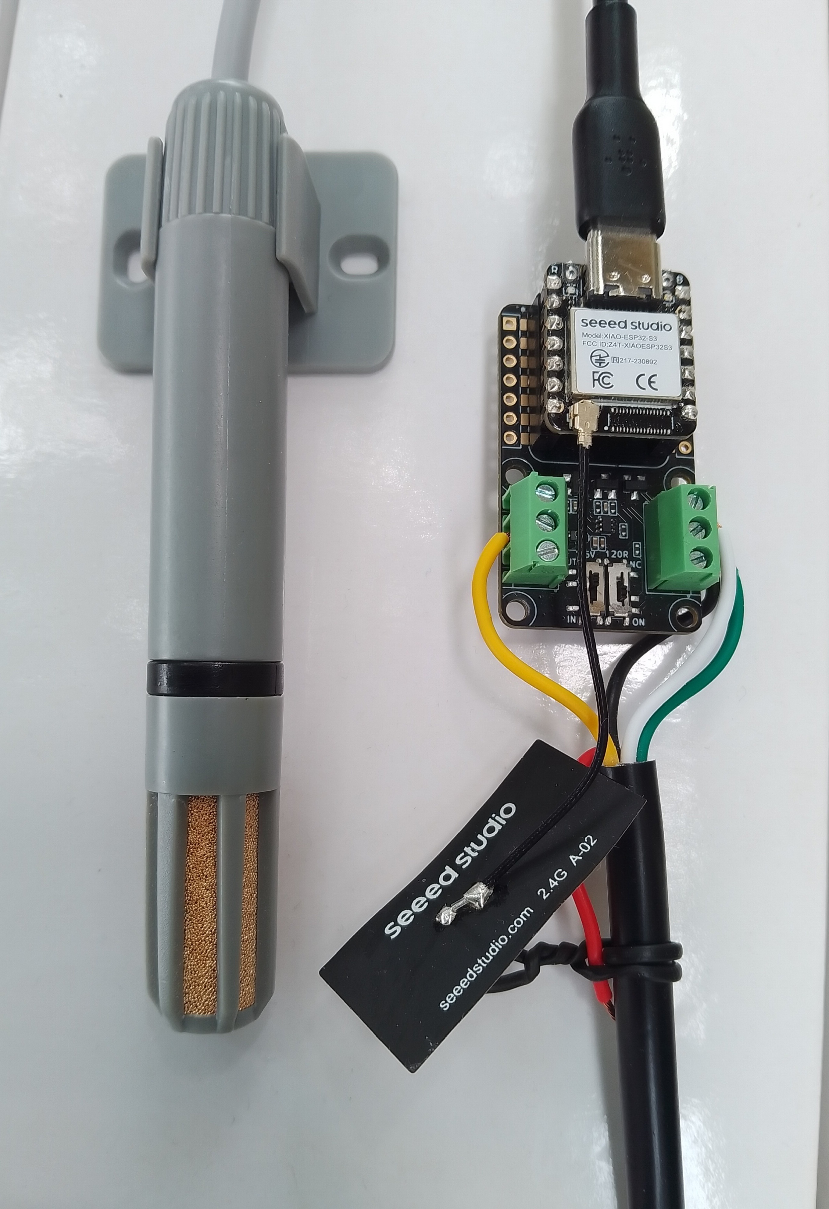
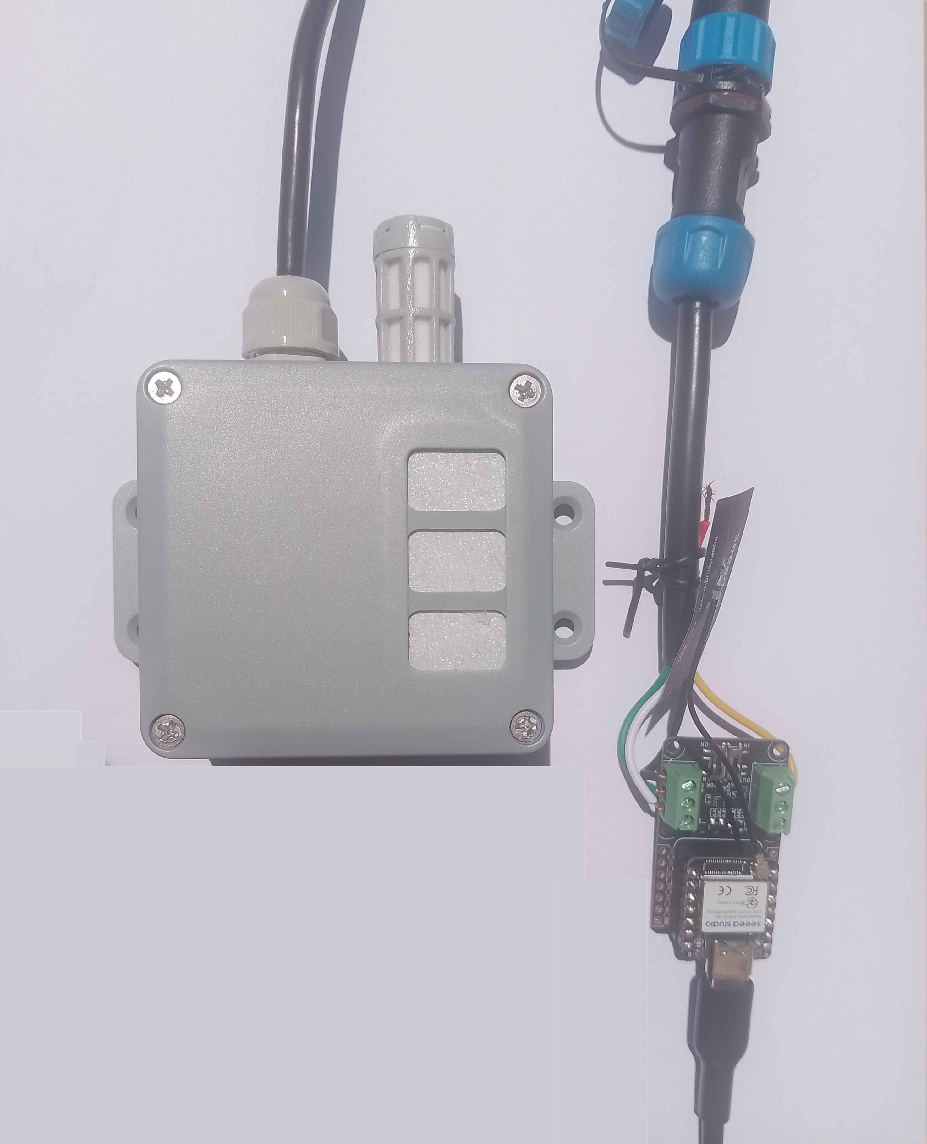
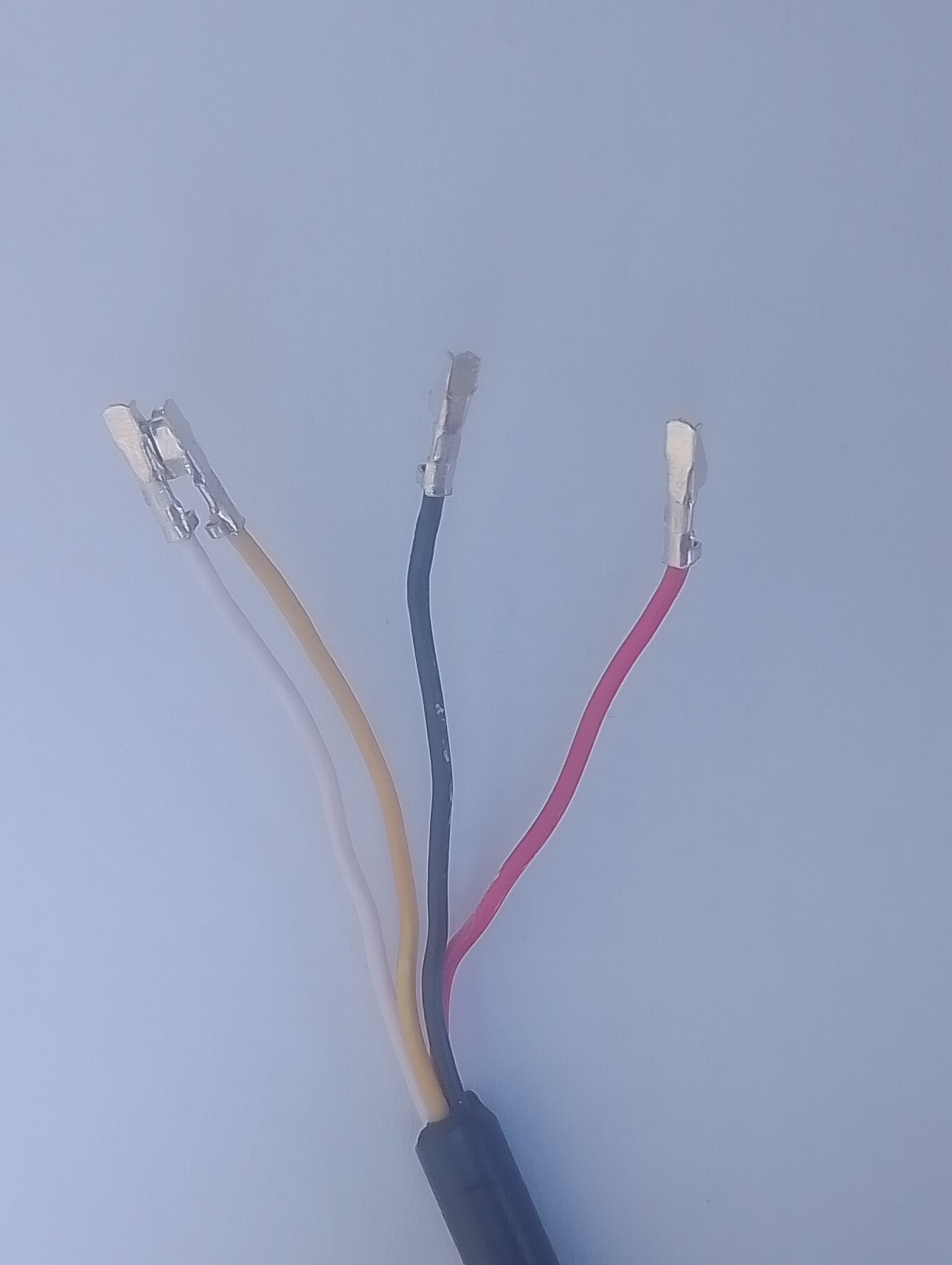
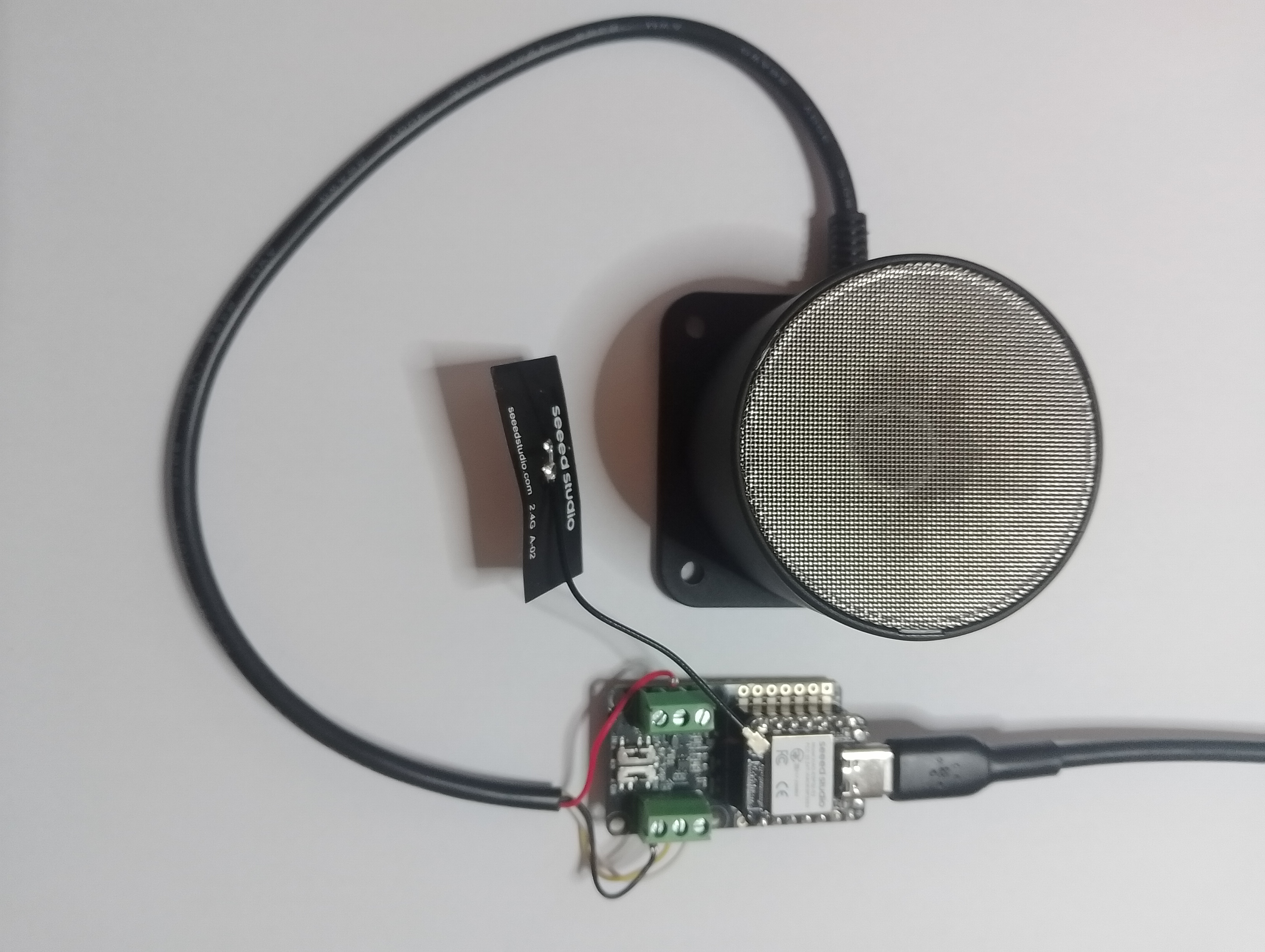
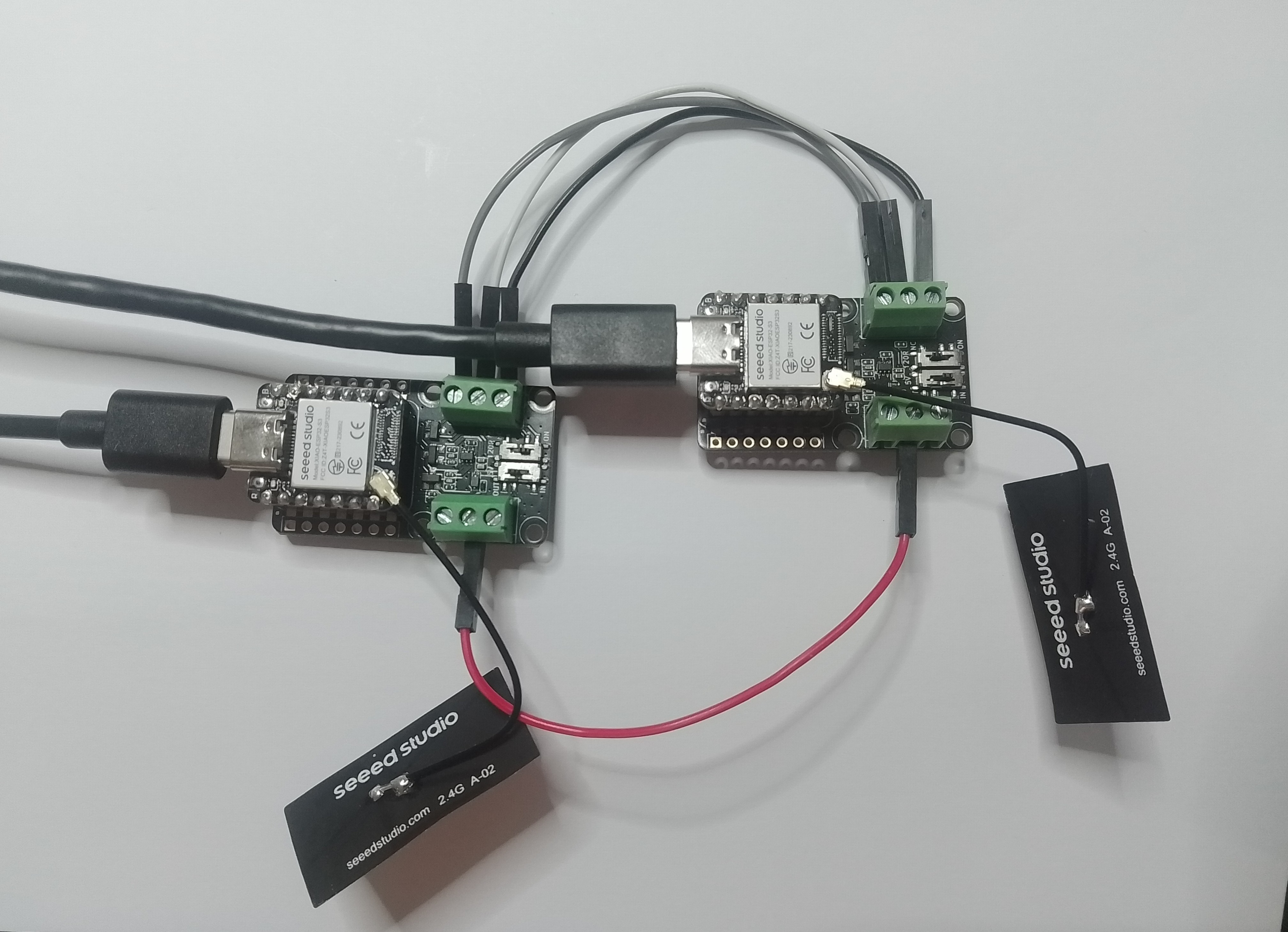
I cut up a spare Industrial IP68 Modbus RS485 1-to-4 Splitter/Hub to connect the sensor to the breakout board as I find this much easier than soldering connectors
This sensor has an operating voltage of 3.6-30V/DC so it can be powered by the 5V output of a RS485 Breakout Board for Seeed Studio XIAO (SKU 113991354). The red wire is for powering the breakout and device with a 12V power supply so was tied back so it didn’t touch any of the other electronics.
HardwareSerial RS485Serial(1);
ModbusMaster node;
// -----------------------------
// RS485 Pin Assignments (Corrected)
// -----------------------------
const int RS485_RX = 6; // UART1 RX
const int RS485_TX = 5; // UART1 TX
const int RS485_EN = D2;
// Sensor/Modbus parameters (from datasheet)
#define MODBUS_SLAVE_ID 0x2A
#define REG_TEMPERATURE 0x0000
#define REG_HUMIDITY 0x0001
#define REG_DEWPOINT 0x0002
// Forward declarations for ModbusMaster callbacks
void preTransmission();
void postTransmission();
void setup() {
Serial.begin(9600);
delay(5000);
Serial.println("ModbusMaster: Seeed SKU101990882 starting");
// Wait for the hardware serial to be ready
while (!Serial)
;
Serial.println("Serial done");
pinMode(RS485_EN, OUTPUT);
digitalWrite(RS485_EN, LOW); // Start in RX mode
// Datasheet: 9600 baud, 8N1
RS485Serial.begin(9600, SERIAL_8N1, RS485_RX, RS485_TX);
while (!RS485Serial)
;
Serial.println("RS485 done");
// Tie ModbusMaster to the UART we just configured
node.begin(MODBUS_SLAVE_ID, RS485Serial);
// Register callbacks for half-duplex direction control
node.preTransmission(preTransmission);
node.postTransmission(postTransmission);
}
...
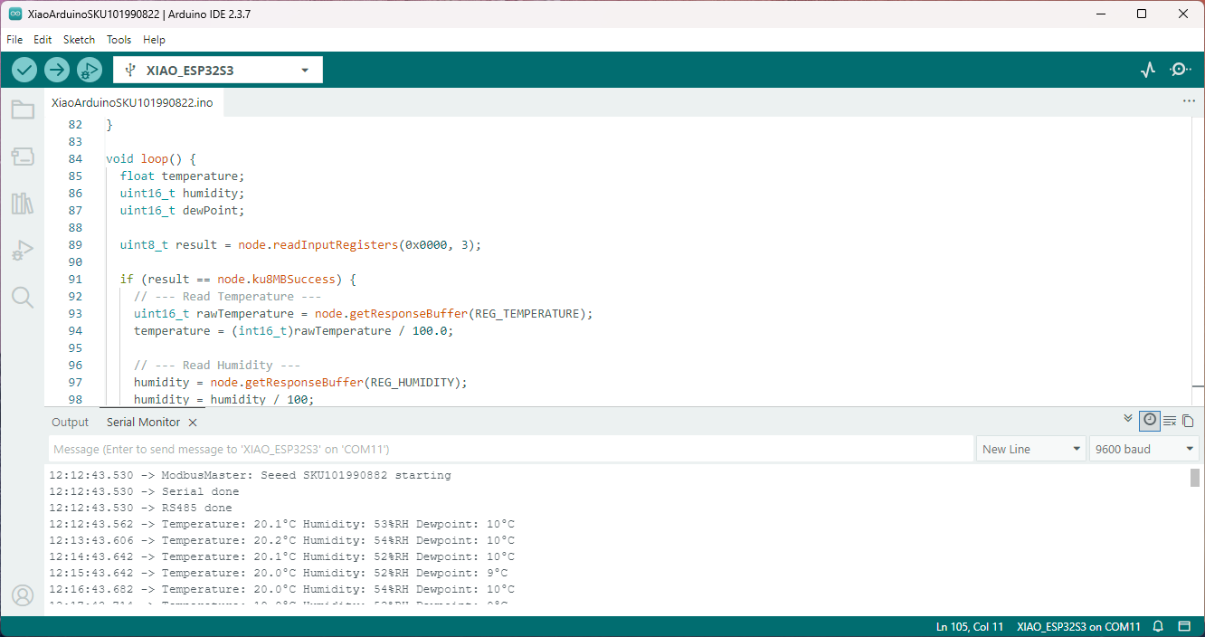
void loop() {
float temperature;
uint16_t humidity;
uint16_t dewPoint;
uint8_t result = node.readInputRegisters(0x0000, 3);
if (result == node.ku8MBSuccess) {
// --- Read Temperature ---
uint16_t rawTemperature = node.getResponseBuffer(REG_TEMPERATURE);
temperature = (int16_t)rawTemperature / 100.0;
// --- Read Humidity ---
humidity = node.getResponseBuffer(REG_HUMIDITY);
humidity = humidity / 100;
// --- Read DewPoint ---
dewPoint = node.getResponseBuffer(REG_DEWPOINT);
dewPoint = dewPoint / 100;
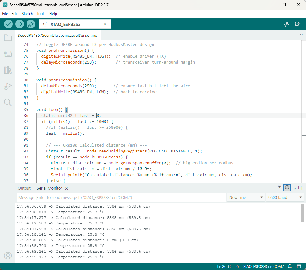
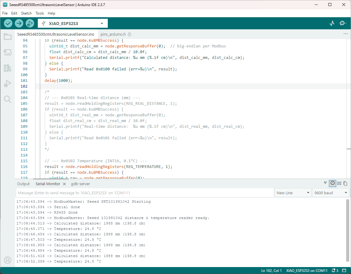
Serial.printf("Temperature: %.1f°C Humidity: %u%%RH Dewpoint: %u°C\n", temperature, humidity, dewPoint);
} else {
Serial.printf("Modbus error: %d\n", result);
}
delay(60000);
}
The Arduino ModbusMaster based application worked first time I forgot to scale the dewpoint.
I have order an Industrial Soil Moisture & Temperature Sensor MODBUS-RS485 sensor from Mouser which will be my next project.